4
ROUBLESHOOTING
T
6828871-R1 EN
3.1 General Procedures
3.1-1 Truck System Requirements
• Truck hydraulic pressure should be within the range
shown in Specifications, Section 5.1. PRESSURE TO
THE ATTACHMENT MUST NOT EXCEED:
• Truck hydraulic flow should be within the range shown in
Specifications, Section 5.1.
• Hydraulic fluid supplied to the attachment must meet the
requirements shown in Specifications, Section 5.1.
3.1-2 Tools Required
In addition to a normal selection of mechanic's hand tools,
the following are required:
• In-line Flow Meter Kit:
10 GPM (37 L/min.) – Cascade Part No. 671476.
OR
20 GPM (75 L/min.) – Cascade Part No. 671477.
• Pressure Gauge Kit:
5000 psi (345 bar) – Cascade Part No. 671212.
• Assorted fittings, hoses, and quick-disconnect couplers
as required.
WARNING: Before servicing any
hydraulic component, relieve pressure
in the system. Turn the truck off and
move the truck auxiliary control valves
several times in both directions.
After completing any service procedure, test the
attachment through several cycles. First test the
attachment empty to bleed any air trapped in the
system to the truck tank. Then test the attachment
with a load to be sure it operates correctly before
returning to the job.
Stay clear of the load while testing. Do not raise
the load more than 4 in. (10 cm) off the floor while
testing.
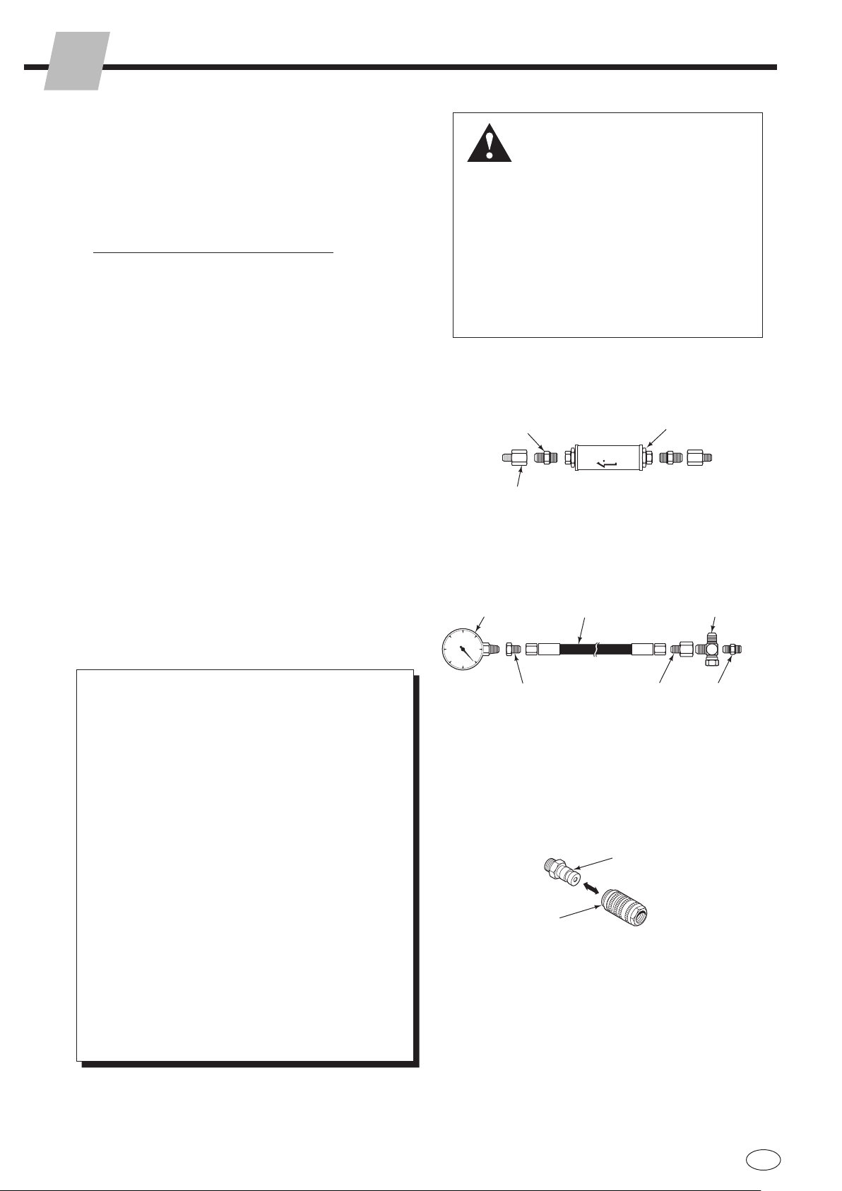
GA0014.eps
Flow Meter Kits
671476 – 10 GPM (37 L/min.)
671477 – 20 GPM (75 L/min.)
(2) No. 8
JIC/O-Ring Flow Meter
(2) No. 6-8
JIC Reducer
Pressure Gauge Kit
671212
Pressure
Gauge ▲No. 6-6 Hose ▲
No. 6 and No. 8
JIC Swivel Tee
No. 6-8 JIC
Reducer
No. 4, No. 6 ▲
and No. 8
JIC/O-Ring
No. 4-6
Pipe/JIC ▲
▲NOTE: Diagnostics Kit
394382 includes items
marked.
Male Straight Thread
O-Ring Coupler:
No. 4 (Part No. 212282) ▲
No. 5 (Part No. 210378)
No. 6 (Part No. 678592)
Female JIC Thread
Coupler:
No. 4 (Part No. 210385) ▲
No. 6 (Part No. 678591)
Quick-Disconnect Couplers
3.1-3 Troubleshooting Chart
Determine All The Facts
It is important that all the facts regarding the problem
are gathered before beginning service procedures.
The first step is to talk to the equipment operator.
Ask for a complete description of the malfunction.
Guidelines below and on the following pages can then
be used as a starting point to begin troubleshooting.
Clamp Circuit
• Attachment drops load after it has been picked up.
• Attachment will not carry load up to its rated
capacity.
• Attachment arms have uneven travel.
• Attachment arms travel slowly.
• Attachment arms will not move.
To correct these problems, see Section 3.3
Sideshift Circuit
• Attachment drops load while sideshifting.
• Attachment drops load at end of sideshift stroke.
• Attachment sideshifts left and right at different
speeds.
• Attachment will not sideshift
To correct these problems, see Section 3.4.
Model Maximum
80G-140G
Low Pressure 1455 psi (100 bar)
High Pressure 2760 psi (190 bar)
170G 2465 psi (170 bar)