Cascade G Series User manual

Cascade is a Registered Trademark of Cascade Corporation
cascade
corporation
ERVICE MANUAL
S
G-Series
Sliding Arm Paper
Roll Clamp
Manual No. 6851096

ONTENTS
C
i6851096
Page
INTRODUCTION, Section 1
Introduction 1
Special Definitions 1
PERIODIC MAINTENANCE, Section 2
100-Hour Maintenance 2
500-Hour Maintenance 2
1000-Hour Maintenance 2
4000-Hour Maintenance 2
TROUBLESHOOTING, Section 3
General Procedures 3
Truck System Requirements 3
Tools Required 3
Troubleshooting Chart 4
Plumbing 5
Hosing Diagram – Standard 5
Hydraulic Circuit – 30G Standard 6
Hydraulic Circuit – 41G-50G Standard 7
Hosing Diagram – Independent Arm Control 8
Hydraulic Circuit – Independent Arm Control 9
Clamp Function 10
Supply Circuit Test 10
Clamp Circuit Test 10
Sideshift Function 12
Supply Circuit Test 12
Sideshift Circuit Test 13
Electrical Circuit 14
SERVICE, Section 4
Attachment Removal 15
Arms 16
Arm Assemblies - Removal and Installation 16
Contact Pad - Removal and Installation 17
Arm Bearing Service 18
Articulating Arm Bushing Service 19
Articulating Arm Adjustment 20
Valve 21
Valve Removal and Installation 21
Standard Valve Service 22
Independent Arm Control Valve Service 25
Relief Adjustments - 30G Standard Valve 26
Relief Adjustments - 41G-50G Standard Valve 27
Clamp Cylinder 28
Removal and Installation 28
Cylinder Disassembly 29
Cylinder Inspection 29
Cylinder Reassembly 30
Solenoid Valve 31
Coil Service 31
Valve Service 31
SPECIFICATIONS, Section 5
Specifications 32
Hydraulics 32
Auxiliary Valve Functions 32
Truck Carriage 32
Torque Values – 30G 33
Torque Values – 41G-50G 34

NTRODUCTION
I
16851096
50G-RSM-4A-0000
123456-01R0
50G-RSM-4A-0000
123456-01R0
RC5060.eps
1. 2 Special Definitions
The statements shown appear throughout this manual
where special emphasis is required. Read all WARNINGS
and CAUTIONS before proceeding with any work.
Statements labeled IMPORTANT and NOTE are provided
as additional information of special significance or to make
your job easier.
WARNING - A statement preceded by
WARNING is information that should be
acted upon to prevent bodily injury. A
WARNING is always inside a ruled box.
CAUTION - A statement preceded by CAUTION is
information that should be acted upon to prevent
machine damage.
IMPORTANT - A statement preceded by IMPORTANT is
information that possesses special significance.
NOTE - A statement preceded by NOTE is information that
is handy to know and may make your job easier.
Nameplate
1. 1 Introduction
This manual provides the Periodic Maintenance,
Troubleshooting, Service and Specifications for Cascade
G-Series Sliding Arm Roll Clamps.
In any communication about the attachment, refer to
the product catalog and serial numbers stamped on the
nameplate. If the nameplate is missing, the numbers
can be found stamped on the frame where the plate was
mounted.
IMPORTANT: Tubing connection and supply fitting types
vary depending on end-user. Specifications are shown in
US and (metric). All fasteners have a torque value range of
±10% of stated value.

ERIODIC MAINTENANCE
P
2 6851096
RC4283.eps
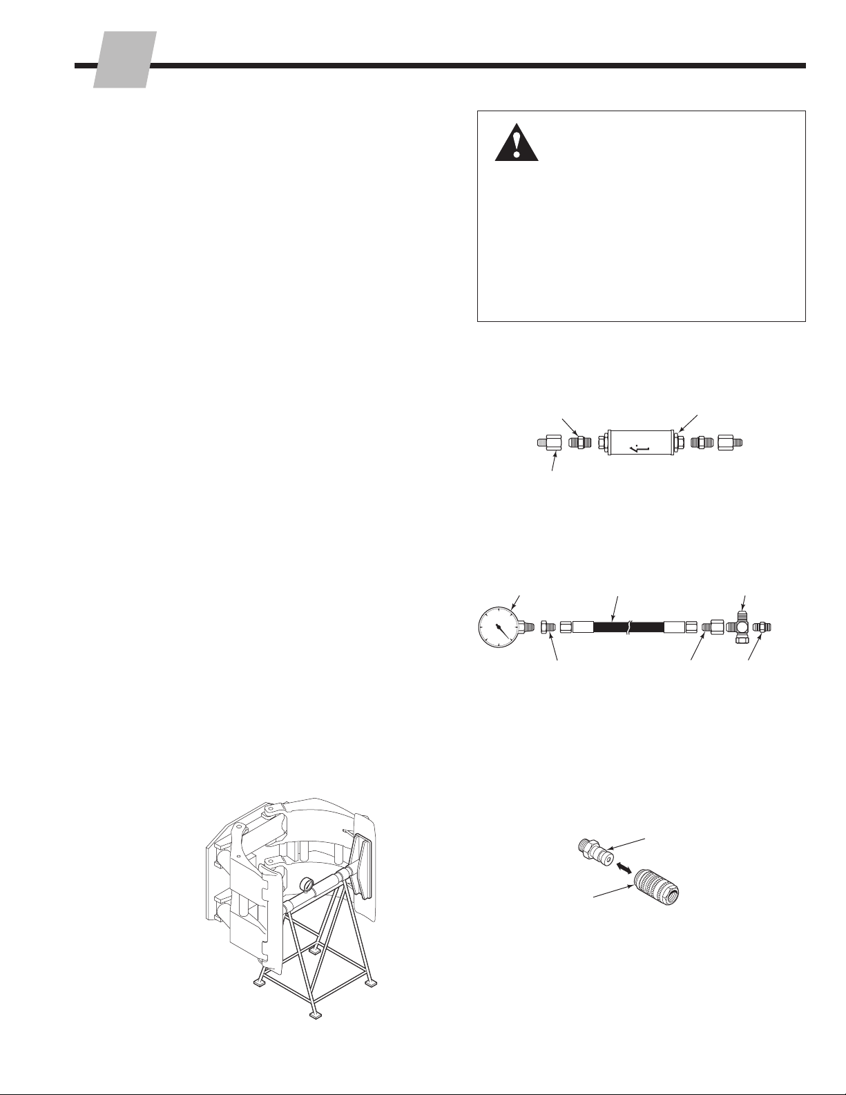
WARNING: After completing any service
procedure, always test the attachment
through five complete cycles. First test
empty, then test with load to make sure
attachment operates correctly before
returning it to the job.
2.1 100-Hour Maintenance
Every time the lift truck is serviced or every 100 hours
of truck operation, whichever comes first, complete
the following maintenance procedure:
• Check for loose or missing bolts, worn or damaged
supply hoses and hydraulic leaks.
• Check decals and nameplate for legibility.
• Inspect the cylinder rod anchor joint for lubrication
and correct hold.
NOTE: Anchor joint operates with a loose
clearance. Lubricate with wheel bearing grease.
• Check for equal arm movement.
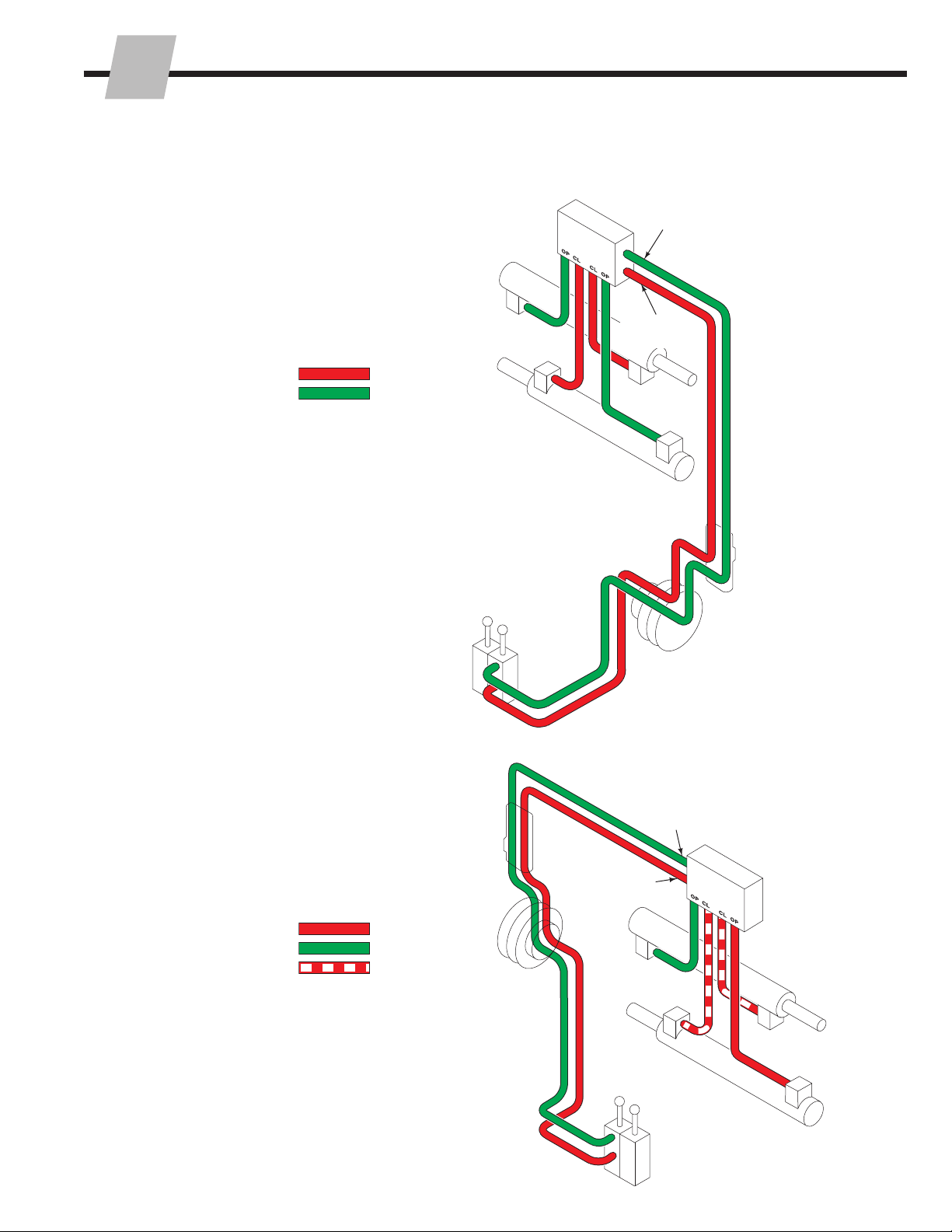
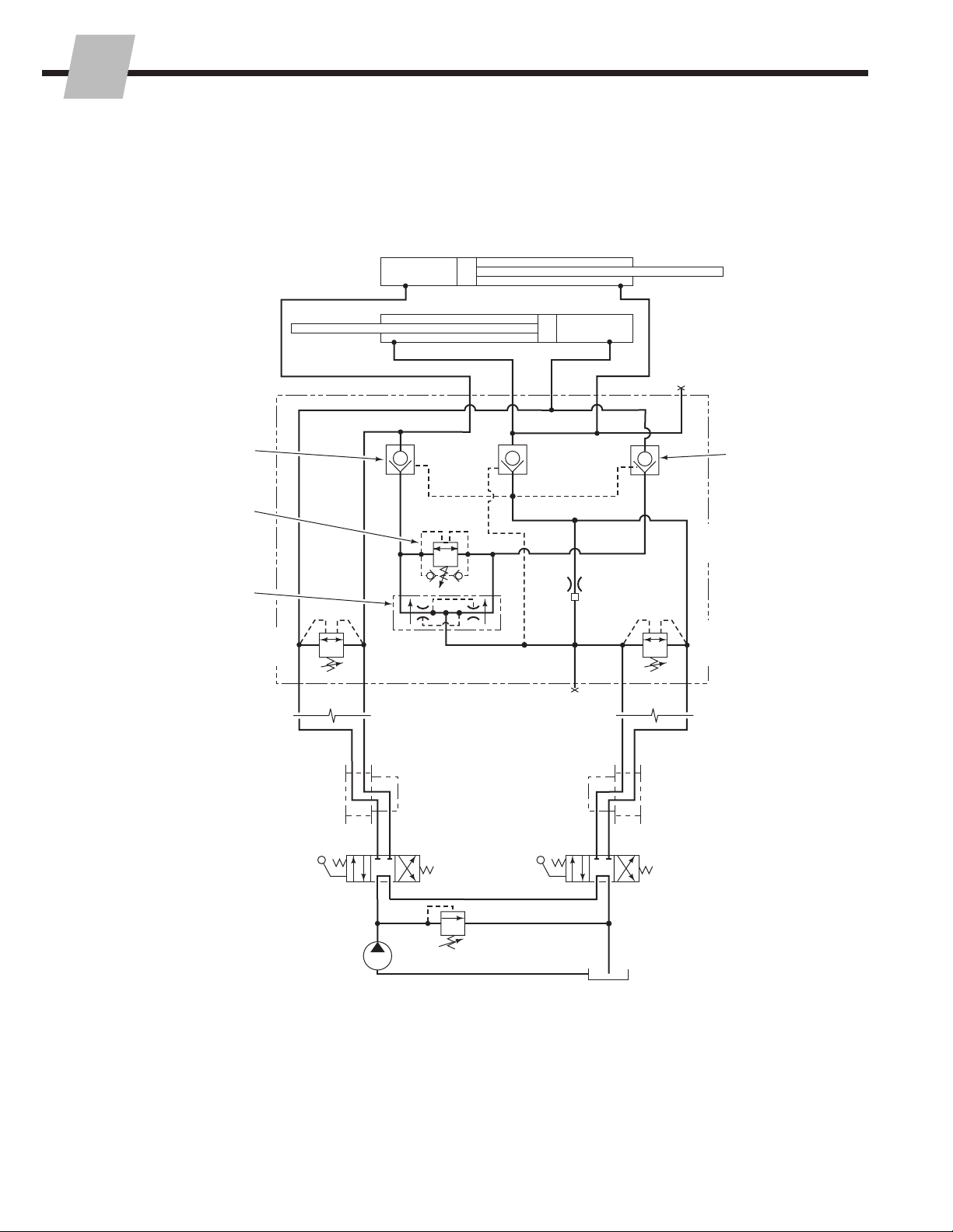
• Check the load holding hydraulic system for
proper function. Cascade Clamp Force Indicators
300G-CFI-812C and 300G-CFI-824C are available
for this test.
2.2 500-Hour Maintenance
After each 500 hours of truck operation, in addition
to the 100-hour maintenance, perform the following
procedures:
• Check the lower mounting hook engagement
clearance with the truck carriage bar:
Quick-Change Hooks – 3/32 in. (2.5 mm) min.
3/16 in. (5.0 mm) max.
Bolt-On Hooks – Tight against lower carriage
bar.
If adjustment is necessary, refer to Section 4.1,
Step 3. Tighten the lower hook capscrews to a
torque of:
CL III – 120 ft.-lbs. (165 Nm)
CL IV – 320 ft.-lbs. (435 Nm)
• Tighten the upper hook capscrews to a torque of
320 ft.-lbs. (435 Nm).
• Inspect all load-bearing structural welds on arms,
frame and cylinder anchor areas for visual cracks.
Replace components as required.
• Inspect contact pads, pivot pins, wear tiles and
arm tips for wear and damage. Replace or repair,
as needed.
2.3 1000-Hour Maintenance
After each 1000 hours to lift truck operation, in
addition to the 100 and 500-hour maintenance
procedures, perform the following procedures.
• Inspect the arm bearings for wear. If any bearing
is worn to less than 0.04 in. (1.0 mm) thickness,
replace all bearings.
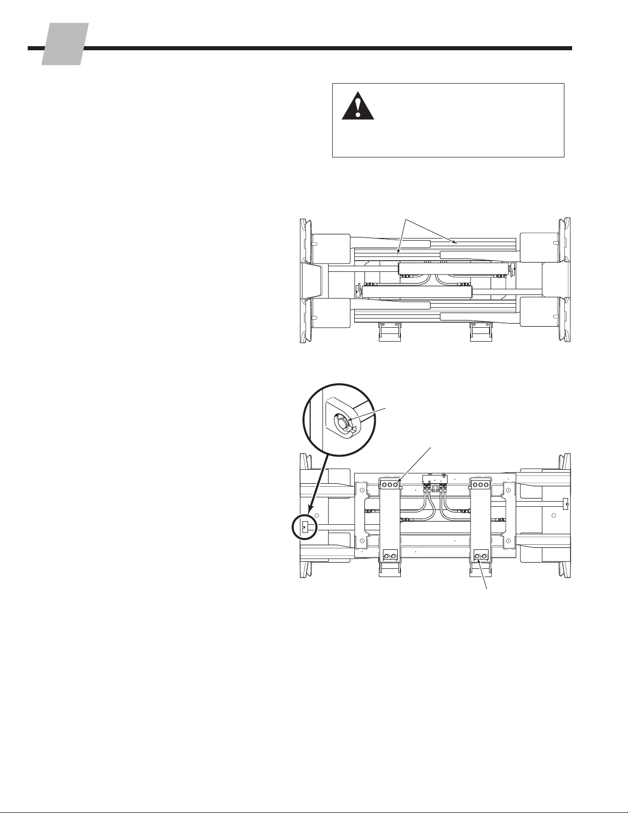
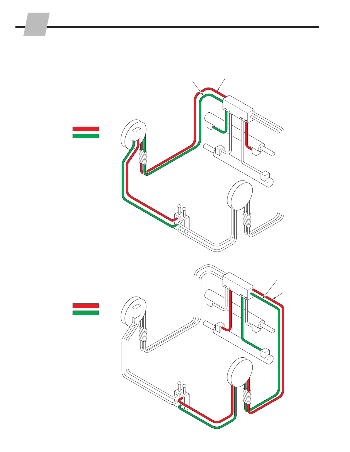
Arm Bearings
Cylinder Anchor Joint
Hook Capscrews
Lower Hook Capscrews
Front View
Back (Driver's) View
2.4 4000-Hour Maintenance
After each 4000 hours of truck operation, in addition to
the 100, 500 and 2000-hour maintenance, perform the
following procedures:
• Due to normal mechanical wear and component
service life, cylinder seals should be replaced to
maintain performance and safe operation.

ROUBLESHOOTING
T
36851096
3.1 General Procedures
3.1-1 Truck System Requirements
• Truck hydraulic pressure should be within the range
shown in Specifications, Section 5.1. PRESSURE TO
THE ATTACHMENT MUST NOT EXCEED:
Low Pressure Valve – 2245 psi (155 bar)
High Pressure Valve – 2755 psi (190 bar)
• Truck hydraulic flow should be within the range shown
in Specifications, Section 5.1.
• Hydraulic fluid supplied to the attachment must meet
the requirements shown in Specifications, Section 5.1.
WARNING: Before servicing any
hydraulic component, relieve pressure
in the system. Turn the truck off and
move the truck auxiliary control valves
several times in both directions.
After completing any service procedure, test the
attachment through several cycles. First test the
attachment empty to bleed any air trapped in the
system to the truck tank. Then test the attachment
with a load to be sure it operates correctly before
returning to the job.
Stay clear of the load while testing. Do not raise the
load more than 4 in. (10 cm) off the floor while testing.
GA0013.eps
GA0014.eps
AC0127.eps
Flow Meter Kits:
671476 – 10 gpm (37 L/min)
671477 – 20 gpm (75 L/min)
(2) No. 8
JIC/O-Ring Flow Meter
(2) No. 6-8
JIC Reducer
Pressure Gauge Kit:
671212
Pressure
Gauge ▲No. 6-6 Hose ▲
No. 6 and No. 8
JIC Swivel Tee
No. 6-8 JIC
Reducer
No. 4, No. 6 ▲
and No. 8
JIC/O-Ring
No. 4-6
Pipe/JIC ▲
▲NOTE: Diagnostics
Kit 394382 includes
items marked.
Male Straight Thread
O-Ring Coupler:
No. 4 (Part No. 212282) ▲
No. 5 (Part No. 210378)
No. 6 (Part No. 678592)
Female JIC Thread
Coupler:
No. 4 (Part No. 210385) ▲
No. 6 (Part No. 678591)
Quick-Disconnect Couplers
AC0037.eps
3.1-2 Tools Required
In addition to a normal selection of mechanic's hand tools,
the following are required:
• In-line Flow Meter Kit:
10 gpm (37 L/min) – Cascade Part No. 671476.
OR
20 gpm (75 L/min) – Cascade Part No. 671477.
• Pressure Gauge Kit:
5000 psi (345 bar) – Cascade Part No. 671212.
• Assorted fittings, hoses, and quick-disconnect couplers
as required.
• Optional – Clamp Force Indicator:
300G-CFI-812C – For solid arms,
Measures 5,000–25,000 lbf
(22.241–124.550 kN)
OR
300G-CFI-824C – For Split Arms,
Measures 5,000–25,000 lbf
(22.241–124.550 kN)
Clamp Force Indicator:
300G-CFI-812C (solid arms)
300G-CFI-824C (split arms)

ROUBLESHOOTING
T
46851096
3.1-3 Troubleshooting Chart
Determine All The Facts – It is important that all the
facts regarding the problem are gathered before
beginning service procedures. The first step is to
talk to the equipment operator. Ask for a complete
description of the malfunction. Guidelines below and
on the following pages can then be used as a starting
point to begin troubleshooting.
Clamp Circuit
• Attachment drops load after it has been picked up.
• Attachment will not carry load up to its rated
capacity.
• Attachment arms have uneven travel.
• Attachment arms travel slowly.
• Attachment arms will not move.
To correct these problems, see Section 3.3-1 and
3.3-2.
Sideshift Circuit
• Attachment drops load while sideshifting.
• Attachment drops load at end of sideshift stroke.
• Attachment sideshifts left and right at different
speeds.
• Attachment will not sideshift.
To correct these problems, see Section 3.4-1, 3.4-2.

ROUBLESHOOTING
T
56851096
CL4994.eps
CL4995.eps
3.2 Plumbing
3.2-1 Hosing Diagram –Standard
CLAMP
PRESSURE
RETURN
NOTE: For OPEN ARMS,
reverse the colors shown.
SIDESHIFT LEFT
PRESSURE
RETURN
SLAVE
NOTE: For SIDESHIFT RIGHT,
reverse the pressure and return
colors shown.
SIDESHIFT CIRCUIT
OPEN/CLAMP CIRCUIT
SSR Port
OP OPEN Port
Cylinders
Cylinders
Hose Reel
or Internal
Reeving
Hose Reel
or Internal
Reeving
Truck Auxiliary
Valve SIDESHIFT
Truck Auxiliary
Valve CLAMP
SSL Port
CL CLAMP
Port
Attachment
Valve
Attachment
Valve

ROUBLESHOOTING
T
66851096
CL5822.eps
3.2-2 Hydraulic Circuit –30G Standard
Cylinders
GA
OR
CLCLOP
CLSSR
OP
OPEN
Check
Valves
OPEN
Check
Valves
CL line
Equalization
Orifice
CLOSE
Check
Valve
Flow Divider/
Combiner
Equalizer
Relief Valve
OPSSL
Hose Reel or
Internal Reeving
Hose Reel or
Internal Reeving
Truck Auxiliary Valve
(CLAMP/OPEN)
Truck Auxiliary
Valve (SIDESHIFT)
Truck Relief
Valve
Truck Tank
Truck
Pump
SIDESHIFT
Relief
CLAMP
Relief
Attachment
Valve

ROUBLESHOOTING
T
76851096
CL4996.eps
3.2-3 Hydraulic Circuit –41G-50G Standard
GA CLCL OP
CL SSR
OP
OPEN
Check
Valves
CLOSE
Check
Valve
Flow Divider/
Combiner
CLAMP
Relief
OPEN
Relief
Equalizer
Relief Valve
Sideshift
Relief Valve
OP SSL
Hose Reel or
Internal Reeving
Hose Reel or
Internal Reeving
Truck Auxiliary Valve
(CLAMP/OPEN)
Truck Auxiliary Valve
(SIDESHIFT)
Truck Relief
Valve
Truck Tank
Truck
Pump
Attachment
Valve
Cylinders

ROUBLESHOOTING
T
86851096
3.2-4 Hosing Diagram –
Independent Arm Control
CL5600.eps
CLOSE LEFT ARM
PRESSURE
RETURN
NOTE: For OPEN LEFT ARM,
reverse the colors shown.
CLOSE RIGHT ARM
PRESSURE
RETURN
NOTE: For OPEN RIGHT ARM,
reverse the colors shown.
CL
(Clamp Port)
CL
(Clamp Port)
OP
(Open Port)
OP
(Open Port)
Cylinders
Cylinders
Hose Reel
or Internal
Reeving
Hose Reel
or Internal
Reeving
Truck
Auxiliary
Valves
Truck
Auxiliary
Valves
Attachment
Valve
Attachment
Valve

ROUBLESHOOTING
T
96851096
3.2-5 Hydraulic Circuit –
Independent Arm Control
CL5601.eps
CL
CL
OPR
GG
OPLCLL CLR
OP
OP
Hose Reel or
Internal Reeving
Left OPEN
Relief
Right OPEN
Relief
Left CLAMP
Check Valve
Right CLAMP
Check Valve
Hose Reel or
Internal Reeving
Truck Auxiliary Valve
(RIGHT ARM)
Truck Auxiliary
Valve (LEFT ARM)
Truck Relief
Valve
Truck Tank
Truck
Pump
Cylinders
Attachment
Valve

ROUBLESHOOTING
T
10 6851096
RC5088.eps
3.3 Clamp Function
There are five potential problems that could affect the
CLAMP function:
• Incorrect load handling. Refer to the Operator’s Guide
for suggested procedures.
• Incorrect hydraulic pressure or flow from the lift truck.
• External leaks.
• Solenoid equipped – Electrical circuit faults, defective
solenoid coil or valve.
• Worn or defective cartridge valves or cylinder seals.
3.3-1 Supply Circuit Test
1 Check the pressure supplied by the truck at the carriage
hose terminal. Pressure must be within the range shown
in Specifications, Section 5.1. See nameplate on the
attachment and sticker on valve. PRESSURE TO THE
ROLL CLAMP MUST NOT EXCEED:
Low Pressure Valve – 2245 psi (155 bar)
High Pressure Valve – 2755 psi (190 bar)
2 Check the flow volume at the carriage hose terminal.
Flow must be within the range shown in Specifications,
Section 5.1.
3 Fully close the arms, holding the lever in the CLAMP
position for a few seconds. Release the lever and
check for external leaks at fittings, hoses and valve.
3.3-2 Clamp Circuit Test
1 Solenoid equipped – Press the solenoid button. Listen
for a 'click' at the solenoid valve. If no sound is heard,
first check the fuse, wiring and coil. Make sure that the
valve is not jammed. Refer to Section 4.5.
IMPORTANT: Solenoid-operated valves must be
plumbed so that the solenoid is energized during the
CLAMP/OPEN function.
2 Fully open and close the arms. Refer to illustration on
next page for cartridge location. Observe clamping
and opening as follows:
• Standard Valve Only – While closing, if arms move
slowly or not at all, the CLAMP relief cartridge may
be faulty or need adjustment.
• While opening, if arms move slowly or not at all,
the OPEN relief cartridge may be faulty or need
adjustment. Replace or adjust cartridge(s).
Standard Valve Only – If arms move unequally, the
FLOW DIVIDER cartridge may be faulty. Replace
cartridge. Refer to Section 4.3.
3 Position the arms to mid-stroke. Turn the truck off and
connect a 5000 psi (345 bar) pressure gauge to the G
port on the valve.
4 Start the truck and clamp on a rigid load or clamp force
indicator. Hold the lever in the CLAMP position for a few
seconds.
WARNING: Before removing hydraulic
lines or components, relieve pressure in the
hydraulic system. Turn truck off and open
the truck auxiliary control valve(s) several
times in both directions.
3Pressure gauge
on valve Gport
4
2Flow Meter on
CL circuit
Front View
RC5086.eps

ROUBLESHOOTING
T
116851096
CL
OP
CL5817.eps
CL5608.eps
5 Release the lever and watch the pressure gauge:
• If the pressure drop is less than 140 psi (10 bar)
initially, and additional drop does not exceed 30 psi
(2 bar) per minute, the problem is not hydraulic.
Refer to Section 3.3.
• If the pressure drop is more than 140 psi (10 bar)
initially, and additional drop exceeds 30 psi (2 bar)
per minute, the CLAMP check valve cartridge may
be faulty. Replace the cartridge. Refer to Section 4.3.
6 Fully close the arms. Hold the lever in the CLAMP
position for a few seconds. If the pressure still drops
(refer to step 5), one of the cylinders is faulty and must
be serviced. Refer to Section 4.4.
CLAMP
Check Valve
CLAMP
Check Valve
Right CLAMP
Check
Left CLAMP
Check
CLAMP Relief
CLAMP Relief
OPEN Check
Flow Divider
Flow Divider
Relief
OPEN Relief
Right OPEN Relief
Left OPEN Relief
CLAMP Supply
Right
Arm
Supply
Left
Arm
Supply
CLAMP
Supply
Flow Divider/
Combiner
41G-50G
STANDARD
VALVE
30G
STANDARD
VALVE
INDEPENDENT ARM
CONTROL VALVE

ROUBLESHOOTING
T
12 6851096
3.4 Sideshift Function
There are six potential problems that could affect the
sideshift function:
• Incorrect load handling. Refer to the Operator’s Guide
for suggested procedures.
• Incorrect hydraulic pressure or flow from the lift truck.
• External leaks.
• Defective solenoid coil or valve (if equipped).
• Worn or defective cartridge valves or cylinder seals.
• Bent or damaged arms, frames or bearing.
3.4-1 Supply Circuit Test
1 Check the pressure supplied by the truck at the carriage
hose terminal. Pressure must be within the range shown
in Specifications, Section 5.1. PRESSURE TO THE
CLAMP MUST NOT EXCEED:
Low Pressure Valve – 2245 psi (155 bar)
High Pressure Valve – 2755 psi (190 bar)
2 Check the flow volume at the carriage hose terminal.
Flow must be within the range shown in Specifications,
Section 5.1.
3 Fully sideshift left or right. Hold the lever in the
SIDESHIFT position for a few seconds. Release the
lever. Check for external leaks at fittings, hoses, and
valve.
WARNING: Before removing hydraulic
lines or components, relieve pressure in the
hydraulic system. Turn truck off and open
the truck auxiliary control valve(s) several
times in both directions.
2Flow Meter
on SS Circuit
Back (Driver's) View
RC5089.eps

ROUBLESHOOTING
T
136851096
CLAMP CLAMP
OPEN
OPEN
SSL
SSR
CL5610.eps
RC5090.eps
Front View
2
NOTE: Perform CLAMP circuit test first to make sure
cylinders are operating properly. Refer to Section 3.3-2.
1 Solenoid equipped – Press the solenoid button. Listen
for a 'click' at the solenoid valve. If no sound is heard,
check fuse, wiring and coil. Make sure that the valve is
not jammed. Refer to Section 4.5.
IMPORTANT: Solenoid-operated valves must be
plumbed so that the solenoid is not energized during
the SIDESHIFT function.
2 Clamp a maximum load. Sideshift LEFT and RIGHT
observing sideshifting movement:
• For each direction, if there is little or no movement,
adjust SSL (or SSR) relief clockwise (CW) until
attachment sideshifts. Then adjust counterclockwise
(CCW) 1/4 turn increments until sideshift speed
slows (relief opening). Finish by adjusting cartridge
clockwise (CW) 1/4 turn.
• If the attachment will not sideshift after attempted
relief adjustment, go to Step 3.
3
Remove the setscrew (4 mm hex socket) and orifice
located in the port on top of the valve, as shown. Re-adjust
SSL and SSR relief per Step 2.
4 If the attachment sideshifts at the proper speed in
one direction but not the other, the SSL and SSR relief
setting can be assumed OK, but the SSL or SSR check
valve may be faulty. Swap or replace check valve
cartridge(s).
• If the attachment still sideshifts improperly in one or
both directions, problem is not hydraulic. Refer to
Section 3.4.
3.4-2 Sideshift Circuit Test
SSL
Check
Valve
SSR
Check
Valve
Sideshift
Check Valve
SSL Relief
Sideshift Relief
SSR Relief
Setscrew
Orifice
SSR
SSL
GA
CL5820.eps
SIDESHIFT
Supply
SIDESHIFT
Supply 41G-50G
STANDARD
VALVE
30G
STANDARD
VALVE

ROUBLESHOOTING
T
14 6851096
3.5 Electrical Circuit
(Solenoid-equipped Clamps)
Use the electrical schematic and diagram shown and
follow the steps below:
1 Check the control knob circuit fuse. Replace if
necessary.
2 Check for loose electrical connections at the truck
ignition switch, control knob button, solenoid coil
terminals and diode.
3 Remove the diode from the solenoid coil terminal. Test
with an ohmmeter for high resistance in one direction
and no resistance in the other direction. If there is no
resistance in both directions, replace the diode.
NOTE: When replacing the diode, the banded (+) end
must be connected to the coil and wiring as shown.
4 Use a voltmeter to determine if correct voltage is
present at the electrical leads when the button is
pressed.
• If there is no voltage at the solenoid, troubleshoot
the electrical circuit for shorts or open circuits.
• If there is insufficient voltage to the solenoid, check
the circuit for excessive voltage drop.
• If there is sufficient voltage to the solenoid, test for
coil continuity. Continue to Step 5.
5 Test for coil continuity and rating by placing an
ohmmeter test lead on each solenoid coil terminal
(ohmmeter on Rx1 scale).
• If there is an ohmmeter reading, the coil is good.
• If the coil is good, but the solenoid does not 'click'
when the control knob button is pressed, the
solenoid cartridge may be jammed.
• If there is no ohmmeter reading, the coil is defective.
Replace coil.
CL0258.eps
CL0257.eps
7.5 Amp
Fuse White
Knob Button
(Normally
Open)
Black
Diode Solenoid Coil
Control Lever Knob
with Pushbutton
7.5 Amp
Fuse
White Black
Diode
User supplied wire Solenoid Coil

ERVICE
S
156851096
RC5091.eps
CL5074.eps
4.1 Attachment Removal
1 Position the attachment arms to frame width.
WARNING: Before removing hydraulic
lines, relieve pressure in the hydraulic
system. Turn the truck off and open the
truck auxiliary control valves several times
in both directions.
2 Disconnect and plug the hydraulic supply hoses to the
Clamp. Tag hoses for reassembly.
3 Disconnect the lower hooks:
Quick-Change Hooks – Remove the locking pins and
drop the hooks into the unlocked position. Replace
the pins in the lower holes. For reassembly, remove
the pins and slide the hooks up to the locked position.
Replace the pins in the top holes.
Bolt-On Hooks – Remove the capscrews and mounting
hooks. For reassembly, tap the hooks tight against the
carriage bar and tighten the capscrews to a torque of:
CL III – 120 ft.-lbs. (165 Nm)
CL IV – 320 ft.-lbs. (435 Nm)
4 Lower the attachment onto a pallet. Tilt the mast
forward and lower the carriage to disengage the upper
hooks.
5 For attachment installation, reverse the above
procedures. For complete installation procedure, refer
to Installation Instructions 6526543.
Sideshift Left
Sideshift Right Clamp
Open
2 2
4
(41G-50G Standard Valve Shown)
3
cascade
®
C-675514-1
RC0367.eps
ADJUST
CL2852.eps
Guide
Quick-Change
Hook
Locking Pin
(Unlocking Position)
Lower Carriage Bar
LH Lower Hook
High Strength
Washer, Capscrew
QUICK-CHANGE LOWER HOOKS BOLT-ON LOWER HOOKS

ERVICE
S
16 6851096
RC5061.eps
WARNING: Check the attachment weight
(located on the nameplate) to make sure
the overhead hoist and chains or straps
are at least the rated capacity of the
attachment.
5 Attach an overhead hoist to the arm assembly. Position
the chain/strap clear of the arm bearing surfaces.
6 Slide the arm assembly out of the frame. Do not
damage the bearings when removing the arm.
7 For reassembly, reverse the above procedures with the
following exceptions:
• Inspect the upper and lower bearings for wear.
Bearing thickness should not be less than 0.04 in.
(1.0 mm) on any part of the bearing. Install new
bearings as a complete set as required.
• Spherical End Nuts – Lubricate the cylinder rod
threads, nut threads and spherical portion of the nut
with wheel bearing grease. Install hex washer on the
rod end with the beveled side facing the arm lug.
4.2 Arms
4.2-1 Arm Assemblies –
Removal and Installation
The following procedures can be performed with the
attachment mounted on the truck.
1 Position the arms to frame width and lower the
attachment arms to 0.05 in. (13 mm) above the floor.
2 Anchor Bar – Remove the cylinder rod anchor bars on
the arm to be removed. Slowly power the cylinder rods
open to expose the rod end. For reassembly, tighten
the anchor bar capscrews to 200 ft.-lbs. (275 Nm).
Spherical End Nuts – Remove the cotter pin, locking
cap and nut retaining the cylinder rod to the arm lug.
For reassembly, tighten nut to 250 ft.-lbs. (340 Nm).
Use a wrench on the hex washer to prevent the rod
from turning. The nut should be tighten against the hex
washer and not tight against the arm lug.
3 Anchor Bar – Slide the rod end block toward the
cylinder to remove the split-ring keepers. Slide the
rod end block off the cylinder rod. Inspect the rod end
block and keepers for wear.
4 Fully retract the cylinder rods.
7
23
7
5Arm
Bearings
Cylinder
Rod
Cap
Spherical
Nut
Arm Lug
Spherical
End Nut
Hex Washer Beveled
Side Facing Lug
CL5003.eps
Nut
CL5302.eps
Anchor Bar
Rod End Block
Arm
Split-Ring
Keepers
Cylinder
Rod End
Capscrews
Anchor Bar Type
Spherical End Nut Type

ERVICE
S
176851096
4.2-2 Contact Pad –
Removal and Installation
The following procedures can be performed with the
attachment mounted on the truck.
1 Lower the attachment until the contact pads lightly
touch the ground.
NOTE: If bolt-on pad surfaces are to be replaced,
remove and replace at this point. Tighten capscrews to
15 ft.-lbs. (20 Nm).
2 Remove the capscrew containing the rubber link under
the hook on the arm. Unhook the rubber link from the
arm. For reassembly, attach the rubber link to the hook
on the arm and install capscrew. Tighten capscrew to
28 ft.-lbs. (38 Nm).
3 Remove the drive pins from the contact pad pivot points
and remove the pivot pins.
4 Remove the contact pad. Rubber pad links can be
removed from the arm by rotating 90° and pulling out.
5 For reassembly, reverse the above procedures with the
following exceptions:
• Install bottom drive pin to contact pad. Install pivot
pin and top drive pin. Make sure drive pins are an
interference fit.
• Check the condition of the rubber link springs.
Replace as required.
• Make sure rubber link is installed as shown.
RC5099.eps
3
4
Drive Pin
2

ERVICE
S
18 6851096
RC5062.eps
4.2-3 Arm Bearing Service
NOTE: Replace all arm bearings if wear exceeds 0.04 in.
(1.0 mm) thickness on any surface. Arms must be removed to
install new bearings as follows:
1 Remove attachment arms as shown in Section 4.2-1.
2 If equipped, remove capscrews with M8 allen wrench. For
reassembly, apply Loctite 242 (blue) to capscrews and
tighten to a torque of 24 ft.-lbs. (32 Nm).
3 Remove the bearing retainer plugs using a 1.56 in. (40 mm)
OD large washer and a M10 x 80L capscrew.
4 Drive new bearings into the frame, displacing the old
bearing.
5 For reassembly, reverse the above procedures with the
following exceptions:
• Install new retainer plugs by using tool capscrew to
drive plug in. Make sure bearing retainer plugs are an
interference (tight) fit in the frames.
NOTE: Use small amount of grease to ease installation.
Bearing
Retainer
Plugs
If equipped,
remove capscrew
Arm Bearing
4
3
2
5
Frame
Bearing
Retainer Plug
(30G Shown)
Arm
Bearings
Turn nut washer CW to extract plug
Capscrew, M10 x 80L
40 mm OD Large Washer
REMOVAL
INSTALLATION
Other manuals for G Series
3
This manual suits for next models
3
Table of contents
Other Cascade Industrial Equipment manuals
Popular Industrial Equipment manuals by other brands

Bilanciai
Bilanciai Cigiemme MERCURY PLUS instruction manual

Thermo Scientific
Thermo Scientific System IV Installation, Operation, Basic Maintenance

KAKA Industrial
KAKA Industrial W-4816Z Operation manual

Emerson
Emerson Fisher ATST Desuperheater instruction manual

ABB
ABB HT569798 Operation manual

ABB
ABB HT580206 Operation manual