Cassese CS 940 User manual

USER & PARTS MANUAL
Version 5
05/2017
Z27456
Version 1
07/2014

USER & PARTS MANUAL
CS940
2
INDEX
I. USER MANUAL / ENGLISH............................................................................................ 4
1SAFETY FEATURES .............................................................................................................................................. 5
1.A POSITION OF THE LABELS ON THE MACHINE. ................................................................................................................5
1.B USER RULES ....................................................................................................................................................................7
1.C WHAT SHOULDN’T BE DONE..........................................................................................................................................7
1.D SAFE USE OF THE MACHINE ...........................................................................................................................................7
2DESCRIPTION ..................................................................................................................................................... 9
2.A DESCRIPTION OF THE CS940 PARTS ...............................................................................................................................9
2.B ACCESSORIES BOX ........................................................................................................................................................10
2.C OPTIONS.......................................................................................................................................................................10
2.D TECHNICAL DATAS........................................................................................................................................................11
2.E CUTTING CAPACITY ......................................................................................................................................................12
2.F NEEDED SPACE .............................................................................................................................................................13
2.G WARRANTY...................................................................................................................................................................14
3HANDLING AND UNPACKING ........................................................................................................................... 15
4INSTALLATION OF THE MACHINE ..................................................................................................................... 16
4.A PUTTING THE MACHINE IN PLACE...............................................................................................................................16
4.B INSTALLATION OF THE ARMS .......................................................................................................................................17
4.B.a Right arm installation ................................................................................................................................................................. 17
4.B.b Left arm installation....................................................................................................................................................................20
4.C ELECTRIC CONNECTION ................................................................................................................................................22
4.D PLUGING THE MACHINE TO THE AIR SOURCE..............................................................................................................22
4.E DUST COLLECTOR CONNECTION ..................................................................................................................................23
5USING THE MACHINE ....................................................................................................................................... 24
5.A STARTING THE MACHINE .............................................................................................................................................24
5.B SAWING........................................................................................................................................................................25
5.B.a Setting the horizontal clamps .....................................................................................................................................................25
5.B.b Setting the vertical clamps (optional)......................................................................................................................................... 25
5.B.c First cut....................................................................................................................................................................................... 26
5.B.d Inside measurement................................................................................................................................................................... 27
5.B.e External measure........................................................................................................................................................................27
5.B.f Cut of the first piece ...................................................................................................................................................................28
5.B.g End of a stick............................................................................................................................................................................... 29
6MAINTENANCE ................................................................................................................................................ 31
6.A OPENING THE COVER ...................................................................................................................................................31
6.B REPLACEMENT OF THE BLADES....................................................................................................................................31
6.C REPLACEMENT OF THE WASTE SUPPORT.....................................................................................................................33
6.D EMPTY THE WASTE BOX...............................................................................................................................................34
6.E PERIODICAL MAINTENANCE.........................................................................................................................................34
6.F DIAGNOSIS ...................................................................................................................................................................35
6.F.a Machine doesn’t start................................................................................................................................................................35
6.F.b The cuts are not nice .................................................................................................................................................................. 35
6.G MONTHLY SAFETY CONTROLS ......................................................................................................................................36
II. MANUEL D’UTILISATION / FRANCAIS......................................................................... 38
1CONSIGNES DE SECURITE ................................................................................................................................. 39

USER & PARTS MANUAL
CS940
3
1.A EMPLACEMENT DES ETIQUETTES DE SECURITE SUR LA MACHINE. .............................................................................39
1.B CONDITIONS D’UTILISATION ........................................................................................................................................41
1.C CE QU’IL NE FAUT PAS FAIRE........................................................................................................................................41
1.D PRATIQUES DE TRAVAIL EN TOUTE SECURITE..............................................................................................................41
2PRESENTATION ................................................................................................................................................ 43
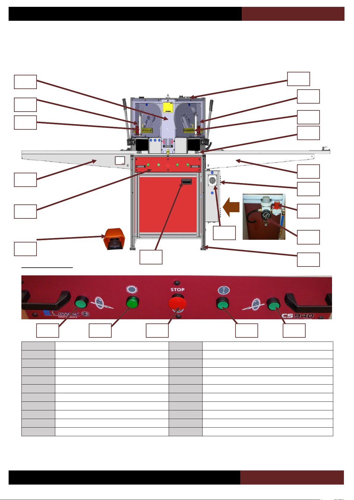
2.A DESCRIPTION DES PRINCIPAUX ELEMENTS DE LA CS940 .............................................................................................43
2.B CONTENU DE LA BOITE D’ACCESSOIRES :.....................................................................................................................44
2.C ELEMENTS OPTIONNELS...............................................................................................................................................44
2.D CARACTERISTIQUES TECHNIQUES ................................................................................................................................45
2.E CAPACITE DE COUPE ....................................................................................................................................................46
2.F PLAN D’ENCOMBREMENT............................................................................................................................................47
2.G RISQUES RESIDUELS .....................................................................................................................................................48
2.H GARANTIE.....................................................................................................................................................................48
3DEBALLAGE ET MANUTENTION ........................................................................................................................ 49
4INSTALLATION DE LA MACHINE........................................................................................................................ 50
4.A MISE EN PLACE DE LA MACHINE .................................................................................................................................50
4.B MONTAGE DES BRAS....................................................................................................................................................51
4.B.a Montage du bras droit................................................................................................................................................................51
4.B.b Montage du bras gauche ............................................................................................................................................................ 54
4.C BRANCHEMENT ELECTRIQUE .......................................................................................................................................56
4.D BRANCHEMENT PNEUMATIQUE ..................................................................................................................................56
4.E ASPIRATION..................................................................................................................................................................57
5UTILISATION .................................................................................................................................................... 58
5.A MISE EN ROUTE............................................................................................................................................................58
5.B SCIAGE..........................................................................................................................................................................59
5.B.a Réglage des presseurs horizontaux ............................................................................................................................................ 59
5.B.b Réglage des presseurs verticaux (optionnels) ............................................................................................................................59
5.B.c Première coupe à gauche ...........................................................................................................................................................60
5.B.d Mesure fond de feuillure ( cote interieure ) ............................................................................................................................... 61
5.B.e Mesure de la cote externe du cadre :.........................................................................................................................................61
5.B.f Coupe du premier morceau........................................................................................................................................................ 62
5.B.g Fin de moulure............................................................................................................................................................................63
6MAINTENANCE &ENTRETIEN........................................................................................................................... 65
6.A PROCEDURE POUR ACCÉDER A L’INTÉRIEUR DE LA MACHINE.....................................................................................65
6.B REMPLACEMENT DES LAMES ......................................................................................................................................65
6.C REMPLACEMENT DE L’ AXE SUPPORT DE CHUTE .........................................................................................................67
6.D VIDAGE DU BAC A CHUTES...........................................................................................................................................68
6.E MAINTENANCE PÈRIODIQUE........................................................................................................................................68
6.F DIAGNOSTIQUE ............................................................................................................................................................69
6.F.a La machine ne démarre pas........................................................................................................................................................69
6.F.b Les coupes sont de mauvaise qualité ......................................................................................................................................... 69
6.G CONTRÔLE MENSUEL DES ORGANES DE SÉCURITÉ .....................................................................................................70
6.H NOMENCLATURE / SPARE PART LIST............................................................................................................................71
III. ECLATES / EXPLODED VIEW ....................................................................................... 81
IV. SCHEMAS ELECTRIQUE / ELECTRICAL SCHEMATICS ................................................... 99
V. CERTIFICATE / CERTIFICAT DE CONFORMITE ............................................................ 103

USER & PARTS MANUAL
CS940
4
I. USER MANUAL / ENGLISH
Your safety is our priority.
This icon in the manual mentions some tricks
that can help you saving time or improve your
production.
This icon in the manual will identify a list of
required tools to perform a procedure.
This symbol in the manual is to mention safety
instructions.

USER & PARTS MANUAL
CS940
5
1SAFETY FEATURES
1.A POSITION OF THE LABELS ON THE MACHINE.
Figure 1-1
2/ Information about pressure
supply.
Figure 1-2
9
11
1/ Identitying plate showing
the technical datas of your
machine.

USER & PARTS MANUAL
CS940
6
7/ This icon on the machine advises you to switch
off electric power before performing maintenance
on the machine.
5/ This symbol shows that it is advised to wear a
dust protecton mask.
4/ This symbol on the machine reminds the
operator to read this manual before operating
this joiner.
6/ This symbol on the machine reminds the
operator to wear acoustic protections and
protection glasses before operating this
machine.
9/. This symbol on the machine asks you to
wear gloves before you touch the blades.
3/ Information about the
locking key and the spin
slocker of the blade.
Figure 1-3
10/ This image advises
you to use only one
blade at a time to avoid
damaging the blades.
Operating both blades
simultaneously is
forbidden.
Figure 1-4
Figure 1-5
11/ These icons are
showing the rotation way
of the blades.
Figure 1-6
12/ This marks are
showing the limit that you
shouldn’t cross with your
hands.
BEFORE PERFORMING ANY MAINTENANCE ON THE MACHINE , UNPLUG AND LOCK THE ELECTRIC AND
PNEUMATIC SUPPLIES. DO NOT USE THE MACHINE IF ONE COVER IS MISSING. READ CAREFULLY THE
SAFETIES INSTRUCTIONS OF THAT BOOK BEFORE OPERATING THE MACHINE.

USER & PARTS MANUAL
CS940
7
1.B USER RULES
The CS940 is a cutting machine able to perform 45° cuts on wood, plastic and MDF .
These materials cannot be cut on this machine :
-Mouldings that don’t have a 90° angle back on at least 5mm.
-Metal profiles.
-Small plastic profiles (filets, etc...).
The 2 blades of this machines are powered by 2 motors. The mouldings are locked in place by 2 horizontal and 2 vertical
(optionnal) clamps. The use of 2 buttons will keep the operators hands in safe position.
The electric safety devices are located in front and in the side panels. Connections are on the right side of the machine
This machine was designed to meet health and safety rules, it is strictly forbidden to modify its electric and pneumatic components. It is
also forbidden to remove protecting covers and to modify its safety devices. The CS940 should be operated only by one person at a
time.
To prevent electric shocks and overload, some protections should be installed by the user on the electric supplying line to the machine
EN60204-1 :2006, Article 7
1.C WHAT SHOULDN’T BE DONE
- At no time the operator should engage his hands in the clamp area, nor in the cutting area behind the brushes. (blades are
rotating even when returned to the top).
- Do not use steel blades (HS type)
- Priorto anymaintenance operation, switch offelectric and pneumatic supplyby using and locking their switches.
- Switch off the machine by using the electric contactor on the right side of the machine.
- Only one person at a time should use the machine.
- All adjustments should be performed with the cover closed. At no moment the operator should put his hands inside the covers.
- If none of the clamps can hold the mouldings, the cut of that moulding is forbidden.
- Do never use the machine with a missing panel.
- These particular mouldings cannot be cut on the CS940
1.D SAFE USE OF THE MACHINE
It is essential that the operators are:
a) Trained about the use, the adjustment and the way of working of the machine.
b) Informed about the things that affects the noise exposition such as :
1) Blades that are designed to limit noise emission
2) Selection of the optimal speed.
3) Maintenance of the blades and of the machine.
c) informed about the things that affect dust exposition such as:
1) Used type of material.
2) Importance of the dust extractor.
3) correct setting of the covers/deflectors.
4) dust collector should be turned on before you start cutting.

USER & PARTS MANUAL
CS940
8
d) Informed about the necessity to wear suffisant individual protection such as :
1) Ear protections.
2) Mask protection against dust to avoid breathing dangerous material.
3) Protecting gloves when touching blades (it is also recommended to use a blade carrying tool to transport the
blades).
It is a necessity for the operator to :
a) Stop the machine and lock the power sources before you perform any maintenance and when the machine is left
without supervision.
b) Report any failure of the machine such as missing cover, damaged parts.
c) Perform cleaning and maintenance to avoid accumulation of the dust and waste inside the machine that could cause
a fire.
d) Not remove any waste or piece of moulding while the machine is in function.
e) Not use the machine if some protection covers are not installed and all in perfect condition.
f) Follow operating, maintenance and repair instructions of cutting blades’manufacturer.
g) Respect the maximum cutting speed of the blades.
h) Use blades that are correctly sharpened.
It is important :
a) That the machine is installed on a flat, cleaned floor.
b) To have a sufficient light in the working area.
c) To have the needed mouldings and finished product stored close to the working area of the operator.
d) Not to do OFF/ON/OFF… in short time, this could damage the machine.

USER & PARTS MANUAL
CS940
9
2DESCRIPTION
2.A DESCRIPTION OF THE CS940 PARTS
Control panel (10) :
1
Cover
2
Left vertical clamp handle
3
Right vertical clamp handle
4
Left vertical clamp
5
Right vertical clamp
6
Moulding guide
7
Left arm
8
Right arm
9
Electrical cabinet door
10
Control panel
11
Safety switch
12
Main circuit breaker (can be locked with a locker)
13
Air pressure regulator
14
Levelling feet (x4)
15
Air switch (can be locked with a locker)
16
Power light
17
Blade stop button
18
Blade start button
19
Left blade acknowledgment button
20
Right blade acknowledgment button
21
Pedal
22
Wastage compartment door
1
9
2
9
3
9
4
9
5
9
6
9
7
9
8
9
10
9
12
9
9
9
11
9
14
9
20
9
16
9
17
9
18
9
19
9
21
9
13
9
15
9
22
9

USER & PARTS MANUAL
CS940
10
2.B ACCESSORIES BOX
The machine is delivered with the following items :
2.C OPTIONS
Allen key N.10 ref : Z1369
Triangular key ref : Z9522
Black cap ref: Z15329
ZZ15329Z1369
Allen key N.4 ref: Z1884
Allen key N.5 ref: Z1885
Allen key N.6 ref: Z1889
Female quick connector
ref : Z749
Connector ref : Z556
US male connector
ref : Z701
The CS940 is not
equiped in standard with
vertical clamps.It is
possible to buy vertical
clamps as an option
under the reference
Z28030.
Using these vertical
clamps will provide
better holding of the
moulding.
A 1.1 meter (about 43
inches) right arm
extension is also
available under the
reference Z27970.
Figure 2-1
Figure 2-2
A replacement waste
cardboard box can be
ordered under the
reference Z27210.
Figure 2-3

USER & PARTS MANUAL
CS940
11
2.D TECHNICAL DATAS
Name……..………………………………………………………………………………………………………………………CS940
Year of manufacturing.………………………………………………………………………………………………………….. 2015
Cutting capacity :
Maximum width………………………………………………………………………………………………………..140 mm
Maximum hig of moulding……………………………………………………………………………………………..75 mm
Dimension of the blades…………………………………………………………………………………………………….Ø 300 mm
Bore…..…………………………………………………………………………………………………………………………. Ø30 mm
RPM………………. ………………………………………………………………..3500 RPM at 60Hz and 2800 RPM at 50 Hz
Maximum lengh to be cut …………………………………………………………………………………………………….1400 mm
Electric supply………... …………………………………………………………………………………….230V Mono / 50Hz-60 Hz
Power cord…………………..………………………………………………………………………………..4 x 1.5 HO7RNF - 4G1,5
2 Motors , power : (conformity EN 30204 )………………………..……………………………………..………………(2X) 1,5 Kw
Dust pipe connectors……….. ………………………………………………………………………………………( 2x ) Ø 100.mm
Dust collector type :
To ensure correct extraction of the dust, sucto should be……………………………………………………1600m3/h at 20m/s
Pneumatic supply………………………………………………………………………………………….6 bars mini / 8 bars maxi.
Air consumption…………………………………………………………………………………………..…0.7 n/l per cycle at 6 bars.
Weight ……………………………………………………………………………………………………………………………167 Kg
Noise : ( ear protections must be wear) Noise information : Measured according ISO 7960-1995 standard).
Noise measuring conditions:
1 metering at operator position, not cutting, dust collector off : ( Véritas testing in process)
9 metering at one meter not cutting, dust collector on : ( Véritas testing in process)
9 metering at one meter, machine in cutting process, dust collector on : ( Véritas testing in process)
These values are measured values, they are not necessarily showing safe working conditions. Even if there is a correspondence
between emission and exposure level, these measures can’t be used to determine the necessary protections to be wear.
Parameters such as workshop configuration, other noise sources and machinery, other manufacturing process can affect the
exposure noise level of the operator.
Also allowed exposure level can fluctuate from a country to another one.
However, these values will help the user to evaluate the risk of using this machine.
Measurement report :: BUREAU VERITAS N° (Véritas testing in process)

USER & PARTS MANUAL
CS940
12
2.E CUTTING CAPACITY

USER & PARTS MANUAL
CS940
13
2.F NEEDED SPACE

USER & PARTS MANUAL
CS940
14
2.G WARRANTY
This machine is covered by a one year warranty, parts and labor included. Wearing parts* and damaged parts due to bad use of the
machine are not covered by the warranty.
* Are considered as wearing parts : waste support, belts, blades, cardboard waste box and clamps’extremities.

USER & PARTS MANUAL
CS940
15
3HANDLING AND UNPACKING
To handle the machine, it
is necessary to use a
Forklift equiped with forks
of minimum 115cm lenght.
The weight of the machine
is 167kgs.
Locate the front facing of
the crate, it is hold in place
by special ears that can be
bent back to open the
door.
Cut the straps closing the
crate and remove the top
cover and top belt (BT).
With the help of a flat
screw driver, bent back the
ears to be able to remove
the front panel of the crate.
Pull on the front facing to
open it.
Take care of not
damaging the profiles
which are stored at the
back of the saw, remove
them before introducing
the forks under the
machine.
Figure 3-1
Figure 3-2
With the help of the
crowbar, remove the side
panels of the crate.
You can then lift the
machine using the forklift.
Insert the forks at the
indicated place in picture
opposite.
Figure 3-3
Figure 3-4
Figure 3-6
Pay attention not to
damage the scales that
are protuding from top of
the arm. They are very
fragile.
Cut the schrink wrap film to
extract the arms of the
machine.
Figure 3-5
Flat screw driver. Crowbar
Protecting gloves Forklift
BT

USER & PARTS MANUAL
CS940
16
4INSTALLATION OF THE MACHINE
4.A PUTTING THE MACHINE IN PLACE
Flat span of 17 bubble level
Flat span of 13
Allen key N.4 & N.5
Figure 4-5
A sufficient space should be around the machine to be able to proceed to its maintenance (see chapter I.2.F NEEDED SPACE
page 13). The machine must be installed on a flat and stable ground. Before to plug it, make sure its feet are adjusted so the
machine is flat and stable. The height of the working table of the machine should be around 900mm, it could be necessary to use
duckboards to ensure small operators a convenient position .
Use your bubble lever
to check the leveling
of the machine as in
picture opposite.
Figure 4-4
Figure 4-1
Unlock the left and
front clamps that are
keeping the cover
closed.
Unlock the right
clamp.
Pivot on top of the
machine the front cover.
Important note : if the
vertical clamps are in
down position, they could
prevent the opening of
the top cover. In that
case, it is necessary to
plug the air to the
machine (refer to chapter
I.4.D PLUGING THE
MACHINE TO THE
AIR SOURCE page 22)
and press the pedal while
opening the cover.
Figure 4-3
Figure 4-2
Make sure the 4 feet (14) are touching the ground. The
machine must be perfectly stable and shouldn’t move
when operating it.
With the flat span of 13
mm unlock the nut (CE).
Then, with the flat span
of 17 mm adjust the
height of the foot (14) to
set the height of the
machine. Lock the nut
(CE) once levelling is
done.
CE
14

USER & PARTS MANUAL
CS940
17
4.B INSTALLATION OF THE ARMS
4.B.a Right arm installation
Allen key N.4 & N.5
Flat span of 10mm
The machine is delivered with its arms and
profiles dismounted :
- Right arm (8).
- Left arm (7).
- Right profile (6).
- Left profile (PRG).
On the right side of
the machine, remove
the screw (V1) and its
locking nut. Keep that
screw to install it back
in the same position
later.
Figure 4-8
Remove the 2 screws
(V2) & (V3) and their
washers from the
inside of the arm.
Discard the nut (V3)
that was just a spacer
for transport to avoid
damaging the scale.
Figure 4-9
Unlock the 3 screws
(ULF) of 4 turns.
Figure 4-10
Figure 4-6
Pay attention, during
handling, to not
damaging the edge of
the scales which are
very fragile.
When installing the machine, make sure the floor is flat and stable, make sure your floor can support the weight
of the machine.
The machine must be installed in a temperate environement with no excessive humidity. Select a position where
the light with be sufficient to light the working bench of the machine.
PRG
6
8
7
V1
V2
V3
Figure 4-7

USER & PARTS MANUAL
CS940
18
Unlock the 2
horizontal screws of 4
turns (see picture
opposite). If needed
use the flat span of
10mm to hold the nut
at the extremity of the
screw.
Figure 4-11
Figure 4-16
Figure 4-17
Figure 4-19
Figure 4-20
Start to install the right
arm (8), taking care of
not damaging the
extremity of the scale.
Figure 4-12
With the help of a
second person holding
the arm, install back
the (V1) screw that
was dismounted in
Figure 4-12. Do not
block the screw yet.
Figure 4-13
Still with the help of
the second person to
hold the arm, put back
the screws (V2) and
(V3), do not block
them.
Figure 4-14
Unlock the 3 screws
under the right arm of
4 turns.
Slide the right arm
profile (6) in the
screw as shown in
the picture opposite.
Figure 4-15
Slide the profile to
center of the saw,
paying attention that
the (ULF) screws are
sliding gently in the
bottom track of the
profile.
Lock the 3 screws
(ULF).
Figure 4-18
Slide the profile until
the stop nut (B) is
reached.
Lock the 2 horizontal
screws back.
B

USER & PARTS MANUAL
CS940
19
Make sure the scales
are well aligned.
Figure 4-22
Figure 4-21
Still with the help of
the second person
holding the arm
levelled, lock the 3
screws under the arm.
Lock the 2 screws
under the arm.
Figure 4-23
With a bubble level on
the arm, hold it in
correct position while
a second person is
locking the front screw
(see following image).
Figure 4-24
Lock the screw (V1) of
the right arm.
Figure 4-25
Install back the
washer and the nut of
the screw (V1). Lock
the nut while holding
the screw with an
Allen key.
Figure 4-26
Remove the adhesive
protection of the arm
scale and stick it on
the table of the
machine.
Figure 4-27

USER & PARTS MANUAL
CS940
20
4.B.b Left arm installation
Unlock of 3 turns the 2
front horizontal
screws.
Figure 4-28
Remove the 2 screws
(V4) and (V5), discard
the nut which was just
installed to avoid
damaging in transport
the scale with a too
long screw.
Figure 4-29
Unlock the 3 screws
(ULF) on the top of the
table.
Figure 4-30
Remove the screw
(V6) in front of the
machine, keep that
screw, nut and washer
as they will have to be
installed in exact
same position.
Figure 4-31
Start to install the left
arm (7) taking care of
not damaging the
scale.
Figure 4-32
Figure 4-33
With the help of a
second person, install
back the screw (V6)
but do not block the
screw.
Figure 4-34
Still with the help of
the second person,
put back both screws
(V4) and (V5) under
the arm.
Slide in the 3 screws
(ULF) and in the 2
front screws the left
arm profile.
Figure 4-35
V6
Table of contents
Languages:
Other Cassese Lathe manuals
Popular Lathe manuals by other brands

Jet
Jet Elite E-1236VS Assembly Instructions and Parts Manual

laguna
laguna Revo 2036 instruction manual

Scotchman
Scotchman 9012-24M manual

Central Machinery
Central Machinery 65044 Set up and operating instructions

Axminster
Axminster Professional AP350WL Original instructions

CEFLA
CEFLA sorbini Smartcoater Laser Roller Manual for use and maintenance-spare parts