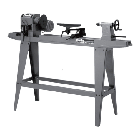
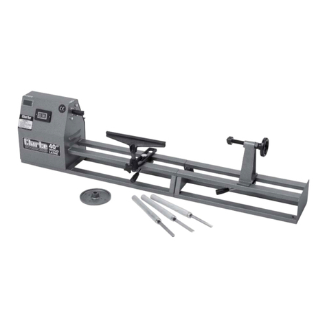
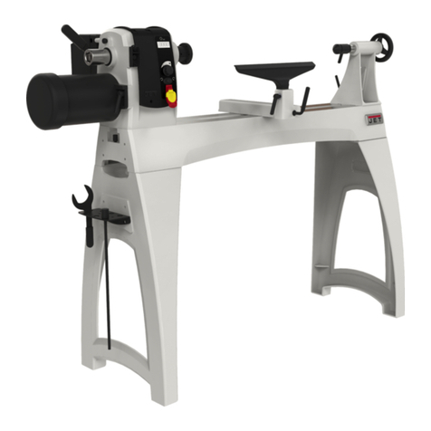
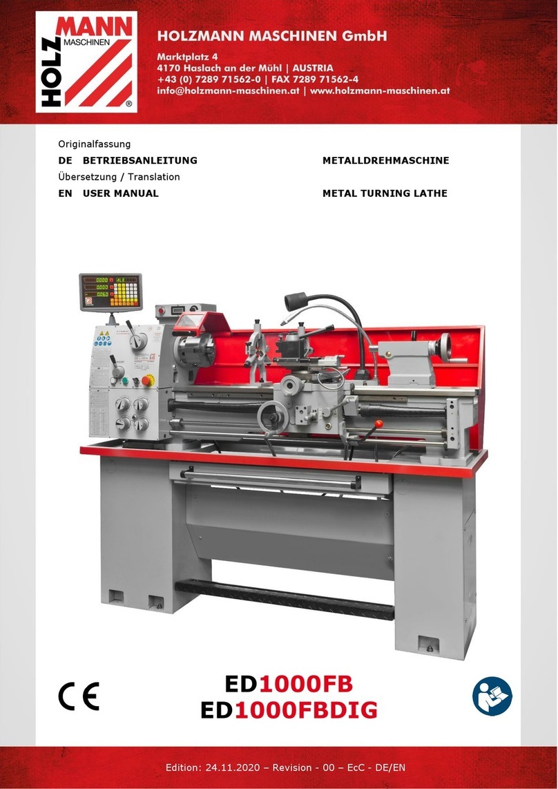
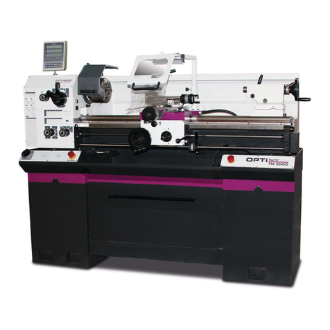
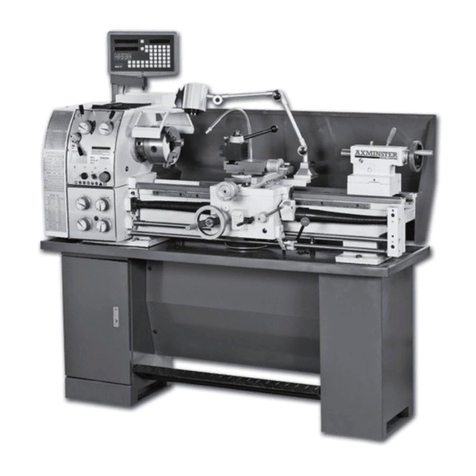
Clarke Woodworker CWL1000V Installation and operation manual

GC02/12
40”(1000mm) WOOD LATHE
Model No CWL1000V
Part No: 6500682
OPERATING & MAINTENANCE
INSTRUCTIONS
OPERATING & MAINTENANCE
INSTRUCTIONS

2
INTRODUCTION
Thank you for purchasing this CLARKE Wood Lathe.
Before attempting to operate the machine, it is essential that you read this
manual thoroughly and carefully follow all instructions given. In doing so you
will ensure the safety of yourself and that of others around you, and you can
also look forward to the product giving you long and satisfactory service.
GUARANTEE
This CLARKE product is guaranteed against faulty manufacture for a period of
12 months from the date of purchase. Please keep your receipt as proof of
purchase.
This guarantee is invalid if the product is found to have been abused or
tampered with in any way, or not used for the purpose for which it was
intended.
Faulty goods should be returned to their place of purchase, no product can
be returned to us without prior permission.
This guarantee does not effect your statutory rights.

3
CONTENTS
Introduction ............................................................................................ 2
Guarantee .............................................................................................. 2
Safety Symbols ....................................................................................... 2
General Safety Rules ............................................................................. 4
Electrical Connections .......................................................................... 7
Main Components ................................................................................. 8
Unpacking & Assembly......................................................................... 9
Operation ............................................................................................. 11
Maintenance ........................................................................................ 12
Accessories .......................................................................................... 13
Troubleshooting .................................................................................... 14
Component Parts ................................................................................. 15
Technical Specification ....................................................................... 18
Declaration of Conformity .................................................................. 19
SAFETY SYMBOLS
The following safety symbols are displayed on the machine.
Wear dust protection
Wear eye protection
Read instructions before use

4
GENERAL SAFETY RULES
Important Note: Although the operation manual contains extensive instruction
on safe working with power tools, every power tool involves a certain residual
risk which cannot be completely excluded. Power tools must therefore
always be operated with caution.
WORK AREA SAFETY
1. Keep work area clean and well lit. Cluttered or dark areas invite
accidents.
2. Do not operate power tools in explosive atmospheres, such as In the
presence of flammable liquids, gases or dust.
Power tools create sparks
which may Ignite the dust or fumes.
3. Keep children and bystanders away while operating a power tool.
Distractions can cause you to lose control.
ELECTRICAL SAFETY
1. Power tool plugs must match the outlet. Never modify the plug in any way.
Do not use any adapter plugs with earthed (grounded) power tools.
Unmodified plugs and matching outlets will reduce risk of electric shock.
2. Avoid body contact with earthed or grounded surfaces, such as pipes,
radiators, ranges and refrigerators. There is an increased risk of electric
shock if your body is earthed or grounded.
3. Do not expose power tools to rain or wet conditions. Water entering a
power tool will increase the risk of electric shock.
4. Do not abuse the cable. Never use the cable for pulling or unplugging the
power tool. Keep cable away from heat, oil, sharp edges or moving part
s.
Damaged or entangled cables increase the risk of electric shock.
5. If operating a power tool in a damp location is unavoidable, use a
residual current device (RCD) protected supply. Use of an RCD reduces
the risk of electric shock.
PERSONAL SAFETY
1. Stay alert, watch what you are doing and use common sense when
operating a power tool. Do not use a power tool while you are tired or
under the influence of drugs, alcohol or medication.
A moment of
inattention while operating power tools may result in serious personal
injury.
2. Use personal protective equipment. Always wear eye protection.
Protective equipment such as dust mask or non-skid safety shoes used in
appropriate conditions will reduce personal injuries.
3. Prevent unintentional starting. Ensure the switch is in the off-position

5
before connecting to power source and/or battery pack, picking up or
carrying the tool.
4. Remove any adjusting key or wrench before turning the power tool on. A
wrench or a key left attached to a rotating part of the power tool may
result in personal injury.
5. Do not overreach. Keep proper footing and balance at all times. This
enables better control of the power tool in unexpected situations.
6. Dress properly. Do not wear loose clothing or jewellery. Keep your hair,
clothing and gloves away from moving parts. Loose clothes, jewellery or
long hair can be caught in moving parts.
7. If devices are provided for the connection of dust extraction and
collection facilities, ensure these are connected and properly used. Use of
dust collection can reduce dust-related hazards.
POWER TOOL USE AND CARE
1. Do not force the power tool. Use the correct power tool for your
application. The correct power tool will do the job better and safer at the
rate for which it was designed.
2. Do not use the power tool if the switch does not turn it on and off. Any
power tool that cannot be controlled with the switch Is dangerous and
must be repaired.
3. Disconnect the plug from the power source before changing accessories,
or storing power tools. Such preventive safety measures reduce the risk of
starting the power tool accidentally.
4. Store idle power tools out of the reach of children and do not allow
persons unfamiliar with the power tool or these instructions to operate the
power tool. Power tools are dangerous in the hands of untrained users.
5. Maintain power tools. Check for misalignment or binding of moving parts,
breakage of parts and any other condition that may affect the power
tool’s operation. If damaged, have the power tool repaired before use.
Many accidents are caused by poorly maintained power tools.
6. Keep cutting tools sharp and clean. Properly maintained cutting tools with
sharp cutting edges are less likely to bind and are easier to control.
7. Use the power tool, accessories and tool bits etc. In accordance with
these instructions, taking into account the working conditions and the
work to be performed. Use of the power tool for operations different from
those intended could result in a hazardous situation.
SERVICE
1. Have your power tool serviced by a qualified repair person using only
identical replacement parts. This will ensure that the safety of the power
tool is maintained.


6
ADDITIONAL SAFETY RULES FOR WOODLATHES
1. IMPORTANT: You should not operate this machine unless you are
thoroughly familiar with woodlathes and turning techniques. If there is any
doubt whatsoever you should consult a qualified person.
2. ALWAYS store chisels safety when you have finished with the machine.
3. CAUTION: This machine is designed for use with wood lathe chisels only.
4. NEVER attempt to turn a workpiece unless a suitable support is used.
5. ALWAYS stop the lathe before removing workpieces, work supports or
swarf from the table.
6. ALWAYS be sure that the workpiece is securely locked in position.
7. ALWAYS keep hands and fingers away from the moving workpiece.
WARNING: DUST GENERATED FROM CERTAIN MATERIALS CAN BE
HAZARDOUS TO YOUR HEALTH. ALWAYS OPERATE THE LATHE IN A WELL
VENTILATED AREA. USE A DUST COLLECTION SYSTEM WHENEVER
POSSIBLE.

7
ELECTRICAL CONNECTIONS
WARNING! Read these electrical safety instructions thoroughly
before connecting the product to the mains supply.
Before switching the product on, make sure that the voltage of your
electricity supply is the same as that indicated on the rating plate. This
product is designed to operate on 230VAC 50Hz. Connecting it to any other
power source may cause damage.
This product may be fitted with a non-rewireable plug. If it is necessary to
change the fuse in the plug, the fuse cover must be refitted. If the fuse cover
becomes lost or damaged, the plug must not be used until a suitable
replacement is obtained.
If the plug has to be changed because it is not suitable for your socket, or
due to damage, it should be cut off and a replacement fitted, following the
wiring instructions shown below. The old plug must be disposed of safely, as
insertion into a mains socket could cause an electrical hazard.
WARNING! The wires in the power cable of this product are
coloured in accordance with the following code:
Blue = Neutral Brown = Live Yellow and Green = Earth
If the colours of the wires in the power cable of this product do not
correspond with the terminal markings of your plug, proceed as follows.
• The wire which is coloured Blue must be connected to the terminal which
is marked Nor coloured Black.
• The wire which is coloured Brown must be connected to the terminal
which is marked Lor coloured Red.
• The wire which is coloured Yellow and Green must be connected to the
terminal which is marked E or or coloured Green.
Plug must be BS1363/A approved
Earth Always fit a 13 Amp fuse.
(Green and Yellow)
Neutral Live
(Blue) (Brown)
Ensure that the outer sheath of the cable is firmly held by the clamp
We strongly recommend that this machine is connected to the mains supply
via a Residual Current Device (RCD).
If in doubt, consult a qualified electrician. DO NOT attempt repairs yourself.

8
MAIN COMPONENTS
A ON/OFF Switch
B Speed Control
C Faceplate
D Tool Rest
E Tool Rest Locking Lever
F Tail-stock Spur Assembly
G Tail-stock Body
H Tail-stock Positioning Handle
A B C E D F G H

9
UNPACKING & ASSEMBLY
When unpacking, check for damage or omissions etc. Any found should be
reported to your CLARKE dealer where the lathe was originally purchased. Do
not discard the packaging until the lathe is assembled.
WARNING: DUE TO THE WEIGHT OF THE LATHE ASSEMBLY, IT IS ESSENTIAL
THAT TWO PEOPLE PERFORM THE UNPACKING, ASSEMBLY AND
POSITIONING.
The numbers in the following assembly instructions refer to the parts lists and
diagrams on pages 15-18.
The following items are supplied loose:
1 x Lathe c/w Adjustable Tailstock
1 x Tool Rest
1 x Tool Rest Holder
1 x Face Plate
1 x Headstock Centre Spur
1 x Tailstock Spur Assembly
2 x Open Wrenches
1 x Fixings Pack
4 x Stand Legs
2 x Stand Long Supports
2 x Stand Short Supports
2 x Stand Top Plates
1 x Stand Shelf Plate
1 x Instruction Manual (this document)

10
ASSEMBLY OF THE STAND
1. Assemble the front & rear legs,
supports and top plates using the
coachbolts, nuts and washers as
shown in Fig 1.
2. Assemble the stand loosely before
tightening all the fixings together.
3. With the help of an assistant,
position the lathe on the top
plates and align the holes in the
lathe bed with the holes in the
stand top plate. Secure with the
bolts & nuts supplied and tighten
them evenly.
ASSEMBLY OF FACEPLATE, TAILSTOCK & LEADSCREW
1. If faceplate turning is required,
screw the faceplate (24) onto the
headstock spindle (42) while using
the open wrench provided to
prevent the spindle from turning.
Tighten the faceplate as shown in
Fig 2.
2. If spur turning is required, insert the
headstock spur (25) into the
tapered hole in the headstock
spindle as shown in Fig 3a.
The spur can later easily be
removed by driving it away from the
headstock using a drift rod through the head spindle.
3. Insert the tail-stock spindle assembly (43/44/45) into the tail-stock as shown
in Fig 3b, the taper of the shaft gripping it in place.
Fig 1
Fig 2
Fig 3a
Fig 3b

11
ASSEMBLING THE HAND CHISEL REST
The standard tool rest for hand
chisels is used as follows:
1. Set the chisel rest holder (54) on
the lathe bed and secure in
position with the securing plate
(53) and the bolt/washer
(51/52) as shown in Fig 4.
2. Position the rest (55) slightly
above the lathe centreline and
approx 3mm from the proposed
workpiece and tighten the
locking handle (59) to secure.
The rest can be used parallel with the workpiece or at 90 degrees for
faceplate turning.
OPERATION
1. Ensure the tool rest and tailstock are securely locked in position before
starting work.
2. Always rotate the workpiece by hand and check it does not strike the tool
rest before switching on the motor.
3. To turn the lathe ON, press the green push-button. Press the red button to
stop.
4. Avoid turning timber which has splits or substantial knots or voids and take
special care if these are discovered.
5. Always use the lowest speed when starting a new workpiece.
6. When turning, always roughly turn the work to a cylinder at low speed.
7. Take care that the chisel does not bite suddenly into the workpiece.
8. Always position the toolrest just above the centreline of the lathe.
Fig 4

12
SPEED CONTROL
1. Set the speed using the speed
control lever as shown in Fig 5.
Always set the lever to the
lowest setting before switching
the machine on or off.
• The following settings serve as
an approximate guide (given
that the control is only marked
600>2200rpm).
GNINRUTELDNIPS
ERAUQS GNIHGUOR GNIHSINIF
"1
"2
"3
"4
0071
0021
007
006
0022
0022
0022
0022
GNINRUTETALPECAF
RETEMAID GNIHGUOR GNIHSINIF
"6
"8
"9
0071
007
006
0022
0022
0022
MAINTENANCE
It is essential that the lathe is properly maintained. Always inspect before use.
Any damage should be repaired and faults rectified. The machine requires
very little maintenance other than the following guidelines.
IMPORTANT - Disconnect from mains power before cleaning.
1. Vacuum clean any dust or shavings that accumulate in or on the motor.
2. Check all cables periodically for security, and that they are in good
condition and not cracked.
3. Check tightness of mounting bolts.
4. Check drive belt for wear and replace if frayed or otherwise damaged.
Fig 5

13
5. Periodically lubricate the tail-stock, copy stock and tool carrier screw
threads with engine oil such as SAE30 grade if they become stiff to use.
6. Lightly lubricate the tail-stock and tool-post locking handles with oil if they
become difficult to use.
• The ball bearings in the headstock and tail-stock spindles and in the copy
live roller pin are greased and permanently sealed at the factory and
require no further lubrication.
REPLACING THE BELT
1. Undo the retaining screws and
remove the belt guard.
2. By pushing the speed control
lever, expand the two halves of
the driven pulley (31) allowing
the belt to adopt its smallest
diameter at this end.
3. Rotate the motor pulley (18/19)
to dismount the drive belt from it
and then lift it off the driven
pulley.
4. Replacement is a reverse of the removal procedure. A broad-bladed
screwdriver or similar will be useful to prize the two halves of the motor
pulley apart against the pressure of the spring (17). Ensure the left & right
halves of the drive pulley spring back to grip the belt and that the belt is in
tension.
In case of problems refer to TROUBLESHOOTING on page 14. If you are unable
to rectify any faults, please contact your local dealer or Clarke International
Service Department on 0208 988 7400 for assistance.
ENVIRONMENTAL PROTECTION
Do not dispose of this product or broken components with general
household waste. All tools, accessories and packaging should be
sorted, taken to a recycling centre and disposed of according to the
laws governing Waste Electrical and Electronic Equipment.
ACCESSORIES
The following range of accessories are also available from your Clarke dealer:
8-Piece Chisel Set Part No: 6500649
4-Jaw Independent Lathe Chuck Part No: 6500645
1/2” Cap. Tailstock Chuck Part No: 6500643
Fig 6

14
MELBORP SESUAC SNOITSEGGUS
nurtonlliwrotoM. .hctiwsnekorb/evitcefeD.1
.elbacrewopdegamaD.2
esool,tiucricnepO.3
denrubrosno
itcennoc
.rotomtuo
rekaerbtiucricroesufnwolB.4
egatlovwoL.5
ruoyotnruterroecalpeR
.riaperrofrelaedekralC
ruoyotnruterroelbacecalpeR
.riaperrofrelaedekralC
rofrelaedekralCruoyotnruteR
ehtriaperotgnitpmettA.riaper
sselnusuodrazahebyamrotom
deifilauqaybtuodeirrac
.naicinhcet
tiucrictes-erroesufecalpeR
rehtoffonruT.rekaerb
.tiucricemasehtnosenihcam
rofylppusrewopehtkcehC
rehtonaesU.egatlovtcerroc
deifilauqaevahrotiucric
rew
opehtedargpunaicirtcele
.ylppus
tratstonlliwrotoM
tiucricrosesufdna
.tuopirtrekaerb
rorotomnitiucrictrohS.
1
.elbacrewop
tiucricrosesuftcerrocnI.2
.srekaerb
rofrelaedekralCruoyotnruteR
.riaper
roesuftcerrochtiwecal
peR
.tiucricehtrofrekaerbtiucric
otsliafrotoM
.rewopllufhcaer
.tiucricdedaolrevO.1
.elbacnoisnetxeelbatius
nU.2
.yrter&senihcamrehtoffonruT
ezistcerrochtiwecalpeR
tadetar(elbacnoisnetxe
mm57.0<
2
.)noitces
.sllatsrotoM.rotomnitiucrictrohS.1
tiucricrosesuftcerrocnI.2
.srekaerb
.tiucricdedaolrevO.3
.egat
lovwoL.4
rofrelaedekralCruoyotnruteR
gniriaperotgnitpmettA.riaper
suodrazahebyamrotomeht
deifilauqaybtuod
eirracsselnu
.naicinhcet
roesuftcerrochtiwecalpeR
.tiucricehtrofrekaerbtiucric
.yrter&senihcamrehtoffonruT
rofylppusrewopehtkcehC
rehtonaesU.egatlovtcerroc
deifilauqaevahrotiucric
.ecivresehtedargpunaicirtcele
n
oitarepoysioN.noisnettlebtcerrocnI.1
.sgniraebnroW.2
eeS.noisnettlebtsujdA
nonoitces"tleBehtgnicalpeR"
.51egap
ruoyotnruterroluahrevO
.riaperrofrelaedekralC
noesoolkcotsliaT
deb
.thgittoneldnahgnikcoLeldnahgnikcol
nethgiT
tasnrubdooW
dnekcotsliat
fokcaL.thgitootteskcotsliaT
.noitacirbul
tnemtsujdakcotsliatffoesaE
.rupsk
cotsliatetacirbuldna
TROUBLESHOOTING

15
COMPONENT PARTS
When requesting spare parts, please quote the reference DDCWL1000V
followed by the number (1-90) on the following parts lists.

16
oN noitpircseD oN noitpircseD
1geLtroppuSdnatS23reveLlortnoCdeepS
2etalPpoTdnatS33gnirpSlioC
3lenaPesaBdnatS438MtuN
421x8MtlobhcaoCdn
atS53mm52x8MtloB
5tuN8M63tfahSlortnoCdeepS
6rehsaW8M738x4MwercSgniniateR
7maeBgnoLdnatS83pilcriC
8maeBtrohSdnatS9350208
gniraeB
9wercSenihcaM5M04retemaidmm25pilcriC
01rehsaW5M14yeKeldnipS
11tuN5M24eldnipSkcotsdaeH
21etalPrevoCeldnipS34ru
pSkcotsliaT
31mm8x5MwercSburG4410208gniraeB
41elbaCrewoP54knahSrepaT
51mm22pilcriC64ydoBkcotsliaT
61rehsaWynneP74eldn
ipSkcotsliaT
71gnirpSlioC8481MtuNgnikcoL
81rotoMyelluP)retuO(94leehwdnaHkcotsliaT
91)rennI(yelluProtoM058x8Mwercsbu
rG
02aidmm5rehsaW1553x61MtloB
12yeKlellaraP25rehsaWmm61
22rotoM35etalProhcnAtseRlooT
32ydoBkcotsdaeH45redloHtseRlooT
42etalPecaF55tseRlooT
52rupSertneC65deBehtaL
62aid42pilcriC75etalPgniruceSkcotsliaT
72)retuo(yelluPnevirD85bonKmrAgn
ikcoL
82ecnarefmucricmm065tleBevirD95eldnaHmrAgnikcoL
92)renni(yelluPnevirD06kcolBgnitcennoC
03aid55pilcriC16knah
SdewercS
136010BgniraeB26wercS
COMPONENT PARTS

17
COMPONENT PARTS
When requesting spare parts, please quote the reference DDCWL1000V
followed by the number (1-90) on the accompanying parts lists.

18
TECHNICAL SPECIFICATION
Please note that the details and specifications contained herein, are correct at the
time of going to print. However, CLARKE International reserve the right to change
specifications at any time without prior notice.
COMPONENT PARTS
oN noitpircseD oN noitpircseD
36mm52x6MtloB38hctiwSFFO/NO
46Fu01roticapaC4821x8MwercS
56revoCroticapaC58pilcriC
77lebaLdeepS68eldnipSlo
rtnoCdeepS
87aidmm8rehsaW78reveLlortnoCdeepS
9702x8MtloB88niPreveLlortnoCdeepS
085,1x61MdnalGelbaC9802x4MwercSknu
s/C
18drauGtleB09maClortnoCdeepS
28wercSgniniateRrevoC---hcnerWnepO
erutaeF noitacificepS
thgieWgk4.85
)HxWxL(snoisnemiD mm0811x554x0441
deepS )elbairav(mpr0022-006
sertnecneewtebecnat
siDmm0001
emarfesabmorfenilertnecfothgieHmm371
yticapaCgninruTmm053
daerhTkcotsdaeHFNU"4/3
repaTkcotsdaeH1TM
re
paTkcotsliaT2TM
ycneuqerF/egatloVgnitarepOrotoMzH05V032
egattaWtupnIW055
tuptuOrotoMdetaRW073
leveLerusserPdn
uoSApL )A(Bd97dedaoL/9.27daoloN
leveLrewoPdnuoSderusaeMAwL )A(Bd29dedaoL/9.58daoloN
KytniatrecnU)A(Bd0.3

19
DECLARATION OF CONFORMITY

This manual suits for next models
1
Table of contents
Other Clarke Lathe manuals

Clarke
Clarke WOODWORKER CWL1000CF Manual

Clarke
Clarke WOODWORKER CWL325V Manual

Clarke
Clarke MetalWorker CL300M Instruction Manual

Clarke
Clarke MetalWorker CL300M Installation and operation manual

Clarke
Clarke WOODWORKER CWL325V Instruction Manual

Clarke
Clarke CWL6B Installation and operation manual

Clarke
Clarke CWL460 Instruction Manual

Clarke
Clarke CWL435 Instruction Manual

Clarke
Clarke WOODWORKER CWL1000CF Instruction Manual

Clarke
Clarke Metalworker CL250M Installation and operation manual