Cassese CS 88 User manual

CS 88 &CS 89
Version 2 au 12 / 06
Cassese / Communication
FOOT-OPERATED
PNEUMATIC
Technical and User Manual
UNDERPINNERS

30403NCOI 3 mm
30404NCOI 4 mm
304 05 NCOI 5 mm
314 05 BDCO 5 mm BD
304 07 NCOI 7 mm
314 07 BDCO 7 mm BD
304 10 NCOI 10 mm
314 10 BDCO 10 mmBD
304 12 NCOI 12 mm
314 12 BDCO 12 mmBD
304 15 NCOI 15 mm
314 15 BDCO1 15 m
Boxes of 6 cartridges (app. 275 wedges) Boxes of 40 cartridges (app. 275 wedges)
(1650 wedges / box) (11000 wedges / box)
30303NCOI 3 mm
30304NCOI 4 mm
30305NCOI 5 mm
31305BDCO 5 mmBD
30307NCOI 7 mm
31307BDCO 7 mmBD
30310NCOI 10 mm
31310BDCO 10 mmBD
30312NCOI 12 mm
31312BDCO 12 mmBD
30315NCOI 15 mm
31315BDCO 15 mmBD
REFERENCE TYPE REFERENCE TYPE
The joining is performed by using metal wedges, a Cassese invention,
designed to ensure very tight corners.
Five standard sizes are available : 5, 7, 10, 12 and 15 mm.
On special request # 3 & 4 are available for slips (filets).
They all come in throw-away cartridges that are colour-coded per size
for easy identification.
Cartridge wedges exist in two versions :
NORMAL for soft and normal timbers and
HW for very hard timbers. These hardwood wedges are to be used only on
hardwoods.
Your CS 88 - CS 89 is designed to use all sizes of Cassese cartridges
without having to change any parts on the machine or having to adjust
anything.
For the long term performance and reliability of your CS 88 - CS 89,
only use genuine CASSESE wedge cartridges.
Beware of bad quality copies that would cause technical problems and
would age your machine prematurely.
CASSESE CARTRIDGE WEDGES
S
O
F
T
H
A
R
D

CONTENTS
INTRODUCTION
ACCESSORIES supplied with the rnachine:
TECHNICAL SPECIFICATIONS
OPTIONS
WARRANTY
LUBRICATION
CLEARING OF A WEDGE STUCK IN THE WEDGE DISTRIBUTOR
IN CASE OF HAMMER AND WEDGE JAMMING
CS 89 / SETTING THE LIMIT SCREW
TROUBLE SHOOTING
1
2-3
4
4-5
7-8
9
10
11
12
MAINTENANCE
CS 88 / CS 89 12 / 06 Cassese Communication
PUTTING INTO OPERATION
MEANS OF ASSEMBLY
SETTING UP THE WEDGE CARTRIDGE
UNDERPINNING THE FRAME
ADJUSTMENTS
USE
CS88 / CS 89 - Technical and User Manual
SELECTION OF STAPLING POSITIONS
5
SETTING AND STORING THE STAPLING POSITIONS
USE OF THE 2 SELF-ADJUSTING BACKFENCES
6
SELECTION OF A TOP PRESSER END / ADJUSTMENT OF THE ASSEMBLY ANGLE
REASSEMBLY
CS 89 AIR LINE FITTINGS
PAGE N°

1
INTRODUCTION
You have just purchased a CS 88 / CS 89. We congratulate you on your excellent choice
and we thank you for your trust.
The CS 88 / CS89 benefits from our long of experience in manufacturing frame assembly
machines which have made us famous. It will assemble wooden mouIdings of any profile (Pa-
tent n’8800188).
The CS 88 / CS89 is designed to permit operators to work in front of the machine or behind it.
Assembly is by metal wedges designed specially to ensure perfect joining.
Use only wedges in cartridges manufactured by CASSESE® (CS trademark).
Beware of copies.
ACCESSORIES supplied with the rnachine:
- 3 allen wrenches ( 2.5 - 3 - 6 ),
- 1 replacement hammer,
- 1 white triangle (for soft woods),
- 1 black triangle for hard woods (mounted on machine)
and its aluminium support,
- 1 tool for removing wedges from distribution head,
- 1 tube of grease
- 1 Spacer bars for small mouldings.
+(CS 89 only) 1 round rubber top presser (yellow for soft woods) + its aluminium
support
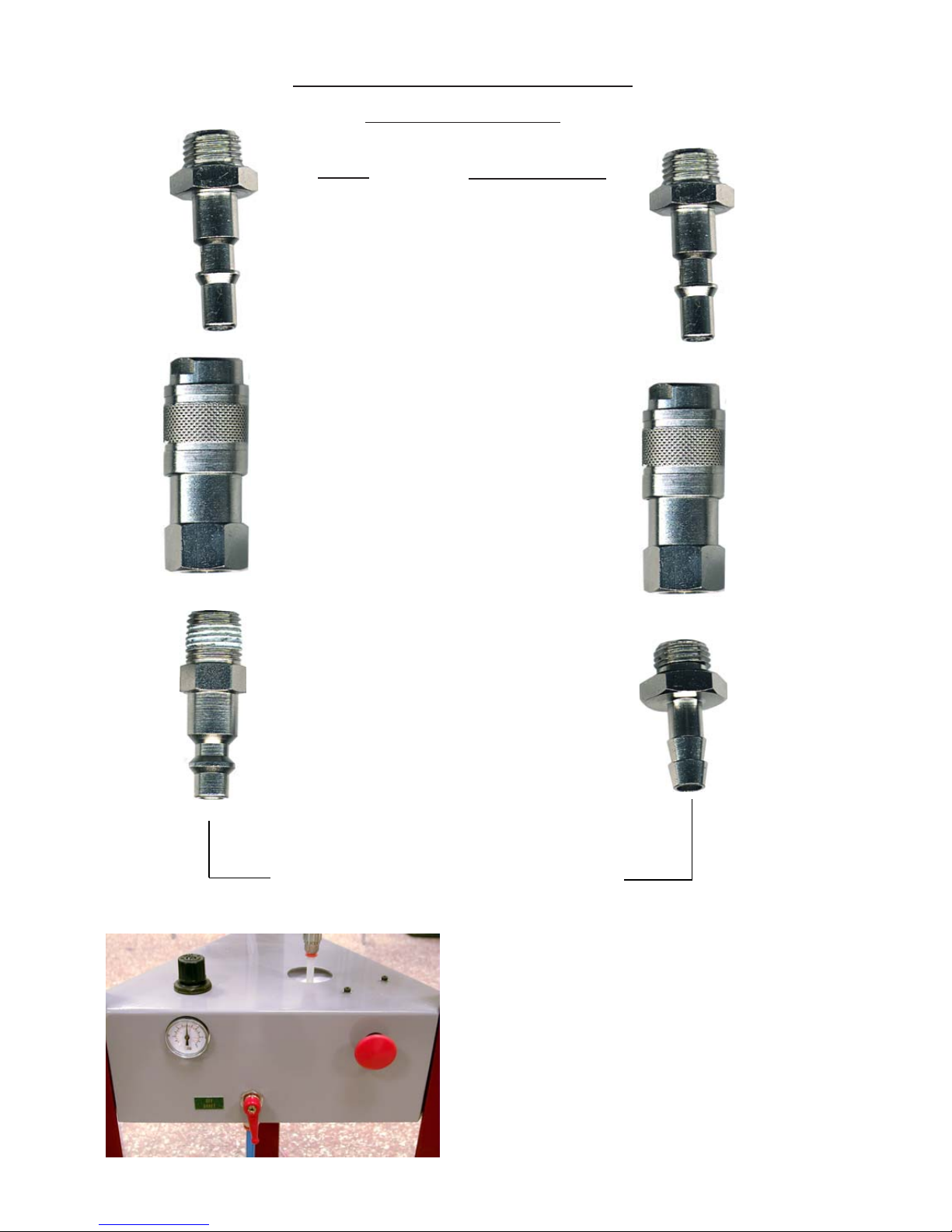
+(CS 89 only) air supply fittings : 1 male connector (on machine) + 1 quick release
female connector + 2 (1 standard + 1 US) hose connectors.
SPECIFICATlONS :
Minimum width of moulding : 5 mm maximum: 95 mm
Minimum height of moulding : 5 mm maximum: 85 mm
Minimum size of frame : 60 x 60 mm (opening) -
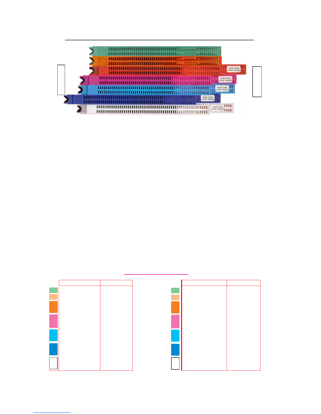
Size of wedges in cartridges of 275 : 3, 4, 5, 7, 10, 12, 15mm
Two types of wedges for : soft wood, hard wood.
Net weight : 25 kg
Dimensions : Width: 600 mm (24’’) Depth: 450 mm (18’’)
Height: 1090 mm (431/2’’)
( CS 89 only) Energy needed : Compressed air 6-7 bars (+/- 100 p.s.i.)
(CS 89 only) air supply : air regulator + manometer, air tube to be used
(inside diameter 8mm) for the standard connector.
OPTIONS
Octogonal, hexagonal inserts or other to order. Other top pressers.
- 3 sockets to attach the machine to the floor:
Insert the part D of the sockets into the holes of the feet
and then fix the sockets to the floor with a screw (not supplied).
WARRANTY
CS 88 / CS89 is covered by a one year warranty for parts and labour and any manufacturing
defects. Worn parts and parts damaged by use not in conformity with the terms of this manual
are not covered by this warranty.
FIXING
SCREW
D

2
REFERENCE POSITION
Fig N°1
ANGLE
ADJUSTMENT
SCREW
TOP PRESSER
BRACKET
WEDGE
DISTRIBUTOR
SLIDING TABLE
TOP PRESSER
B1
LEFT BACKFENCE
HORIZONTAL
CLAMP /
REBATE CLAMP
Fig N°2
STOP FOR
STAPLING POINT
INNER SIDE OF
THE FRAME
STOP FOR
STAPLING POINT
OUTER SIDE
OF THE FRAME
B2
RIGHT BACKFENCE
AS
IMPORTANT : For the best,
and most efficient function of
your CS 88-89 machine, we
advise you to carry out the ad-
justments exactly in the order
of this manual.
CS89 AIR CONNECTION
SEE PAGE 3
PUTTING INTO OPERATION
For safety during transportation, the moving parts of your CS 88 – 89 have been blocked : these
are the Top Presser Bracket (or Plunger) / Sliding Table / Horizontal (rebate) Clamp.
For the explanations given in this manual, the operator must be standing at the back of the
machine, keeping the machine slightly in his left. (See REFERENCE POSITION below). In this
position, the operator is always in the same distance to the corner, regardless of the size of the
frame.
Advice : to work frames of bigger sizes easily, you can put the CS 88-89
machines in front of your work bench (make sure that the work bench is not
higher than the machine). The CS 88-89 machines have been conceived in a
triangle form to fit any work bench : if you wish so, you can cut one of the
corners of your work bench, to locate the machine in this corner. This way,
while making big sized frames, you will not be using more than one of the
corners of your work bench.
WIRE FOR
WEDGE
PUSHING SPRING

3
The CS 89 is to be connected to the air
source under its lower grey plate, at the
level of air valve V.
Then turn the air valve V to ON. Make sure
that the air pressure shown on the
manometer is 6 bar (85 p.s.i.) otherwise
correct it with the regulator D.
D
VEMERGENCY
STOP
Manometer
CS 89 AIR LINE FITTINGS
USA
AIR SOURCE (compressor)
Male Connector
on Machine
Q/R US male
connector
quick release (Q/R)
female air connector
Standard hose
connector
Z 675 Z 675
Z 749
Z 701 Z 556
STANDARD
Advised way of fitting :

SETTINGS
4
USE OF THE 2 SELF-ADJUSTING BACKFENCES
Position a moulding against the LEFT
backfence.
Loosen the locking knob B.
Press the moulding against the table T,
tilt the backfence so that it fits behind
the moulding, then tighten knob B.
Position the second moulding on the
RIGHT backfence and repeat the
operation.
B
T
As a general rule a MINIMUM 2 mm clearance (less than 1/8”) above the wedges shall be
respected.
Same sized wedges can be stacked in order to avoid to have to change the cartridge size when
joining frames with different thickness.
AS A GENERAL RULE, THE JOINING MUST BE CARRIED OUT AS
CLOSE TO THE THICKEST MOULDING PART(S) AS POSSIBLE .
SELECTION OF STAPLING POSITIONS
The CS 88 / 89 is designed to join mouldings in one or two places (positions) without limitation
of the number of wedges in any of those places. The selection depends on the width and thick-
ness of the moulding to join.
2 mm MINIMUM
2 mm MINIMUM
(Approx.1/8’’)
(Approx.1/8’’)

Second stapling position:
Inner side of the frame:
Move the sliding table backwards and
align the wedge outlet of the distributor
with the required stapling position.
Slide stop P1 (inner stapling stop)
against the sliding table, then lock it.
First stapling position:
Outer side of the frame:
Move the sliding table forwards and align
the wedge outlet of the distributor D with
the required stapling position. Slide stop
P2 (outer stapling stop) until its buffer
comes into contact with the sliding table,
then lock it.
Position the first moulding against stop
B1 and slide it up to stop B2.
5
Release the stapling positioning stops, P1 and P2.
SETTING AND STORING THE STAPLING POSITIONS
P 1 P2
B1
REFERENCE POSITION
B2
B
1) UNDERPINNING WITH 2 STAPLING POINTS
WEDGE OUTLET
P2
P1
D
D
SLIDING
TABLE
2) UNDERPINNING WITH 1 STAPLING POINT
Position the right moulding against the self-adjusting backfence. Move the sliding table so that
the wedge outlet coincides with the required stapling point.
Lock the inner stapling stop P1. Then push the outer stapling stop P2 until its buffer B comes
into contact with the sliding table, then lock it.

6
The triangle top pressers with their support that are
included with your CS 88 / 89 give you the capacity
to work mouldings up to 85 mm (1”½). For taller or
complicated mouldings, there are other top pressers
available from your regular source of Cassese products.
If the corner is open towards outside, unscrew (turn anti-clockwise) the angle adjustment
screw AS (see Fig 1 page 1) a little to correct the fault and check again.
ADJUSTMENT OF THE ASSEMBLY ANGLE
If several cutting machines are being used in your production or if you receive your mould-
ings already cut by your suppliers (chop service), the angles of the mouldings will be slightly
different from one cutting machine to the other. The joining angle of your CS 88 / CS 89 can
be adapted to find precisely the cutting angle of your cutting machine.
If the corner is open towards inside, screw in (turn clock-wise) the angle adjustment screw
AS (Fig 1 page 1) to correct the fault.
Ifyou getthisresult, checkyour cutting angle,which iswrong
in this case because it is less than 45°.
Carry out the adjustment of the angle of your cutting
machine.
IT IS IMPOSSIBLE TO MAKE A RECTANGLE
FRAME WITH ANGLES SMALLER THAN 90°.
Outside
Inside
PRESSER
MOULDING
SELECTION OF A TOP PRESSER END
Make sure that the distance between the moulding’s top and the presser’s bottom is not
more than
If the distance is bigger than this, use another
(longer) top presser to reduce the distance.
CS88
35 mm
MAXIMUM
CS89
50 mm
MAXIMUM
BLACK TRIANGLE PRESSER FOR HARDWOODS Fixing in support with
WHITE TRIANGLE PRESSER FOR SOFT WOODS 2.5 mm Allen key.
GREEN ROUND RUBBER ENDS FOR HARDWOODS 1 long and 1 short
YELLOW ROUND RUBBER ENDS FOR SOFT WOODS 1 long and 1 short
Triangle top pressers are good for flat mouldings or for mouldings representing a flat or horizontal area to come down
on. The round rubber ends are good for complicated forms (uphill, downhill or reverse mouldings).
For very tall mouldings the round rubber ends can be also inserted into the top presser bracket without their
support to gain capacity in height.

7
USE
1
2
3
SETTING UP THE WEDGE CARTRIDGE
Move the sliding table forwards to allow access to the
cartridge. (1)
Pull the positioning cord back, using the ball as a grip. (2)
Push the cartridge fully home in the distributor slot. (3)
Release the wedge pusher cord carefully to avoid
damaging the pusher and spring.
Note: For easier changing of the wedge magazine during
operation, the wedge cartridge can be accessed by lifting
the sliding table from the rear with the finger.
The joining is performed by using metal wedges, a Cassese invention,
designed to ensure very tight corners. Seven sizes are available : 3, 4, 5, 7,
10, 12 and 15 mm. They come in throw-away cartridges that are colour-
coded per size for easy identification. Cartridge wedges exist in two ver-
sions : NORMAL for soft and normal timbers and HW for very hard tim-
bers. These hardwood wedges are to be used only on hardwoods.
Your CS 88 / CS 89 machine is designed to use all sizes of Cassese car-
tridges without having to change any parts on the machine or having to
adjust anything.
For the long term performance and reliability of your CS 88 / CS 89,
only use genuine CASSESE cartridge wedges.
Beware of counterfeit products.
MEANS OF ASSEMBLY

The stapling points are defined (see Defining the stapling point, page 5).
The joint angle has been checked (see Setting the joint angle, page 6).
The distance between the top of the moulding and the bottom of the top clamp is outside
permissible maximum. (See Choice of top presser, page 6).
Correct size wedges (normal wood or hard wood) have been loaded in the machine.
UNDERPINNING THE FRAME
Unscrew the knob of the top clamp, then
move the rebate clamp against the 2
mouldings, without forcing. Lock the
rebate clamp knob again, without pushing
it. Clearance of around 1 mm is left to
make it easier to move the mouldings dur-
ing assembly.
Position the first moulding against the right stop and slide it up to the left stop.
Keeping the first moulding secure, position the second moulding against the left stop, then slide
it into contact with the first moulding.
Position the rebate clamp:
Move the sliding table forwards or backwards to stop P2 or P1 (page 5).
Then:
CS 88
Keeping the mouldings secure, slowly push down the pedal.
When the rebate clamp comes into contact with the moulding, speed up the movement so that
the wedge is inserted more easily.
To stack wedges*
- Release the pedal until the top clamp begins to lift.
- Push the pedal down again.
* When stacking wedges, the sliding table should be locked in place.
CS 89
Keeping the moulding secure, gently push the pedal so that the two mouldings are secured by the
rebate clamp.
Then press the pedal down fully to insert the wedge.
If there is a second stapling position, keep your foot pressing down on the pedal, move the slid-
ing table to the second position, raise your foot slightly then push fully down to insert the second
wedge.
Then release the pedal completely.
Note: If several wedges are inserted, raise your foot slightly to keep horizontal pressure on the
mouldings, then push fully down: the second wedge is inserted and pushes the first wedge fur-
ther in.
8

9
MAINTENANCE
6mm MAXIMUM ( 1/4’’ )
WEDGE REMOVING TOOL
DISTRIBUTOR
( BLOCK H )
WEDGE EXIT
1) LUBRICATION
Periodically, remove the wedge distributor (Fig 1, block H) and clean it (by air gun) without dis-
mounting it.
It is recommended to lubricate the hammer (driver blade) periodically. To do so, remove the
wedge distributor (blockH) and put a small quantity of grease in the bottom hole of the wedge
distributor. The hammer will be lubricated every time it crosses the wedge distributor.
2) CLEARING OF A WEDGE STUCK IN THE WEDGE DISTRIBUTOR
If you push the foot pedal half way and release, a wedge may be half engaged in the wedge
distributor. In this case,
- Close the air valve (CS 89).
- Try to remove the cartridge that is in position. If it resists, use the wedge removal tool to push
down the wedge back in the cartridge.
- Pay attention not to make penetrate the tool more than 6mm (¼”) into the wedge distributor.
It is important not to leave a wedge half engaged in the wedge distributor, as it may cause
the insertion of two wedges when you join the next corner or may cause the jamming of
the hammer (the driver blade) in the wedge distributor.
- In case of the hammer (driver blade) jamming with a wedge in the wedge distributor, see the
following section (3).

PROCEDURE
3) IN CASE OF HAMMER AND WEDGE JAMMING
10
HAMMER
BLOCK H
BLOCK H
locking screw
HAMMER
RETAINING
SCREW
Z1394
A
BC
D
GF1
GF2
D
E
BLOC H
SCREW POSITIONS
If you have any difficulty to remove the block H from the machine, push down
with your hands the top presser’s bracket arm.This should free the block H that
is stuck with the hammer.
- Remove the cartridge that is on machine, and the top presser.
- Using the 3mm Allen key, loosen the locking screw of the wedge distributor Block H.
- Then lift the top presser’s bracket arm by hand. The wedge distributor will come out of its
housing. Remove it from the machine.
- The old hammer (wedge driver blade) is stuck in the wedge distributor : first try to remove it
with a pair of pliers. If not possible, unscrew the two central screws (GF1, GF2) that hold the
fixed (square) guide of Block Hin place. Use for this the smaller (2.5mm) Allen key supplied
with the machine. Remove the fixed guide completely to free the old hammer. If still not possi-
ble to get rid of the old hammer, remove the four screws (A, B, C, D) and open the block H.
- Remove the old hammer. Assemble the Block Hback again.
Putting a new hammer (driver blade) :
- Put a drop of grease in the bottom hole of the wedge distributor (block H).
- Insert a new hammer into block H with the hole of the hammer downwards.
- Re-position the wedge distributor in its housing on the machine with the window towards the
cartridge.
- If the upper end of the hammer stays out of the block H, push it fully in with a piece of wood
or moulding.
While keeping the moulding in place (on block H) and pressing on it, pull up the top presser’s
bracket arm Po (Fig1 p1) with a quick movement.
The new hammer must have taken its position in the mechanism automatically.
- Check with your finger or with a ruler that the block Hdoes not stay out of the machine
(higher than the work level) and tighten the locking screw of block H. No need to tighten too
much.
- The machine is ready to work again.
fig 0
RULER
WEDGE
DISTRIBUTOR
(BLOCK H)
SLIDING
TABLE
LOCKING SCREW

CS 89 SETTING THE LIMIT SCREW
LIMIT
SCREW
LIMIT
DETECTOR
CS
89
WARNING!
ONLY CARRY OUT THIS
OPERATION IF IT IS
RECOMMENDED IN THE
TROUBLESHOOTING
REMEDIES AT THE END
OF THE MANUAL.
1) Take out the wedge cartridge.
2) Reduce the air pressure to 3 bars.
3) Set the plunger at less than 50 mm (2’’) from the table.
4) Holding nut E, turn the limit screw through 2 to 3 turns.
5) Press the pedal as if to start up stapling; as the limit detector is not actuated, the plunger re-
mains in low position.
6) Unscrew the limit screw until the plunger moves upwards.
7) Once the plunger has lifted, unscrew the limit screw by an additional quarter turn.
E
11

TROUBLESHOOTING
FAULT POSSIBLE CAUSES REMEDIES
NO WEDGES ARE INSERTED
INTO THE MOULDING
THE WEDGE IS NOT FULLY
INSERTED INTO THE
MOULDING
THE WEDGE BREAKS
MOULDINGS DIFFICULT
TO MOVE
STAINS ON BACK
POOR JOINING
- Corner open on inside
- Corner open on outside
- Opening on top and bottom
of joint
- Mouldings marked by
triangle rubber top pressor
THE WEDGE DRIVER BLADE
DOES NOT LOWER
- The wedge cartridge is empty
- The wedge distributor is clogged
- The wedge spring is broken or relaxed
- The wedge driver blade is broken
- Top clamp / Moulding distance not
within permissible maximum
- Moulding not adequately secured on the
table
- Wedge driver blade damaged
- Hard wood
ANGLE OFFSET - The first moulding was not pushed firmly against the left stop (page 5)
- The rebate clamp is too tight against the
mouldings.
- Too much grease on the wedge driver
blade
- Bad cut
- Incorrect setting
- Incorrect setting of stops
- Triangle rubber top pressor for hard
wood used on soft wood
- Misalignment
- Fit a new wedge cartridge
- Clean it
- Check the condition of the spring
and replace if necessary
- Change the wedge driver blade
(page 10)
- Reposition the plunger within
permissible maximum distance
(page 6)
- Secure the moulding firmly on
the table
- Change the wedge driver blade
- Use hard wood wedges (page 7)
- When the rebate clamp is tight-
ened do not push it towards the
mouldings
- Clean the wedge driver blade
- Repeat the cut
- Loosen the AS screw (page 2-4)
to compensate for opening
- Check the self-adjusting
backfences before starting under-
pinning
- Use a suitable triangle rubber top
pressor (page 6)
- Contact after-sales service
IF THE PROPOSED REMEDIES DO NOT SOLVE THE PROBLEM CONTACT THE AFTER-SALES SERVICE
THE PLUNGER DOES NOT
LIFT
- Limit screw incorrectly set - Check the setting of the limit
screw
- Air supply pressure less than 6 bar - Increase the pressure
- Wedge jammed in the wedge distributor - Dismantle the wedge driver blade
to remove the wedge (page 10)
- Limit screw incorrectly set - Reset the limit screw (page 11)
- Distance between bottom of top clamp
and top of moulding outside permissible
maximum
- Reposition the plunger and expel
any wedge that may have gone
into the wedge distributor using
the tool supplied (page 9)
12
88-89
89
88-89
88-89
88-89
88-89
88-89
88-89
88-89
88-89
88-89
89
88-89
88-89
88-89
88-89
88-89
88-89
88-89
88-89
89

SUB-ASSEMBLY
SOUS ENSEMBLE
KOMPLETTE EINHEIT
CONJUNTO
+ Nû 7909A Nû 7919
+ Nû 7909 to Nû7919
+ Nû 7909 zu Nû7919
Valable ˆ partir de la machnine Nû
Valid from machine #
V‡lido de la m‡quina Nû
Gultig ab der mashine Nû
7927
-02

This manual suits for next models
1
Table of contents
Other Cassese Power Tools manuals