Castex CASC505 User manual

1
AUTOMATIC TYRE CHANGER
CASTEX CASC505
Authorized representative:
Anna Bednarz
ul. Fordońska 44C
85-719 Bydgoszcz
tel. 52 515 64 22

2
Instructions for use of the tyre assembly system.
INDEX
1. Introduction ...............................................................................................................................2
2. General safety rules................................................................................................................. 33
.................................................................................................................................................... 3
3. Technical data......................................................................................................................... 33
.................................................................................................................................................... 3
4. Transport................................................................................................................................ 34
.................................................................................................................................................... 3
5. Rozpakowywanie ..................................................................................................................... 44
.................................................................................................................................................... 4
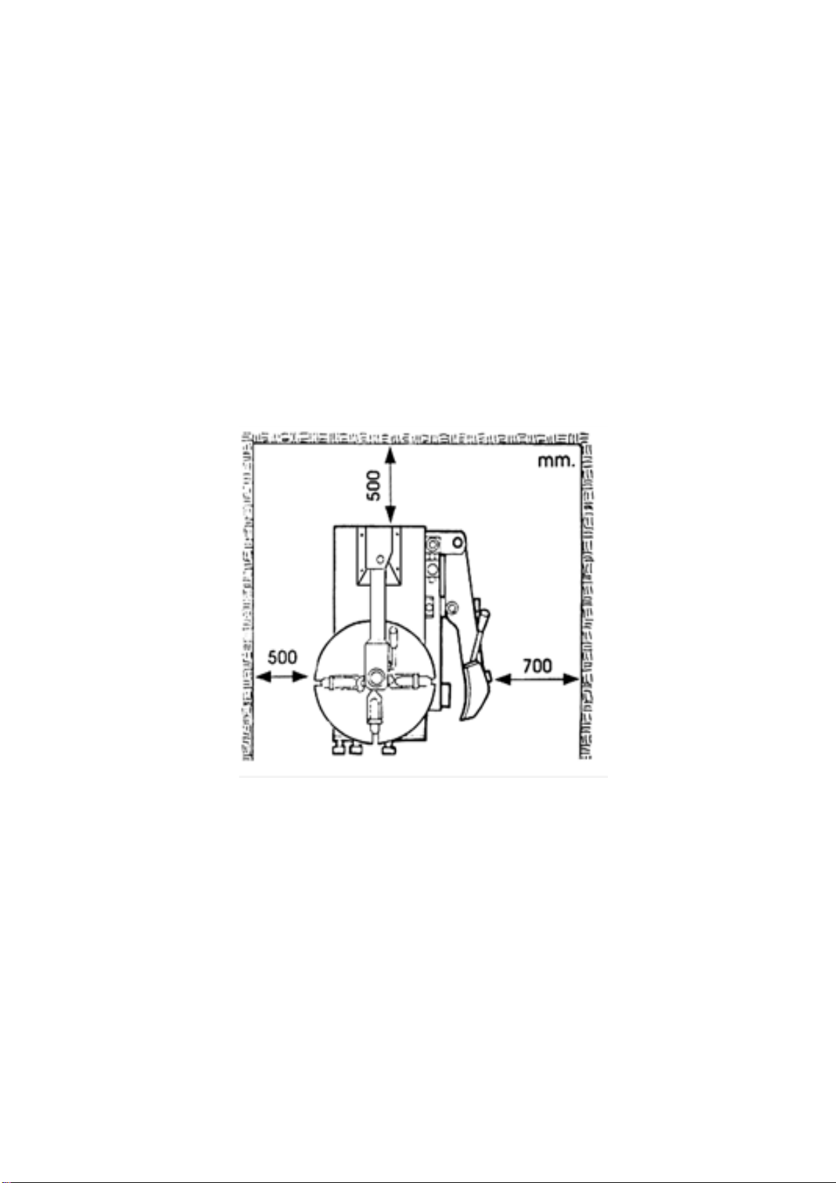
6. Workplace............................................................................................................................... 44
.................................................................................................................................................... 4
8. Installation method.................................................................................................................. 66
.................................................................................................................................................... 6
9. Pneumatic connector: .............................................................................................................. 66
.................................................................................................................................................... 6
10. Electrical connector................................................................................................................ 67
.................................................................................................................................................... 6
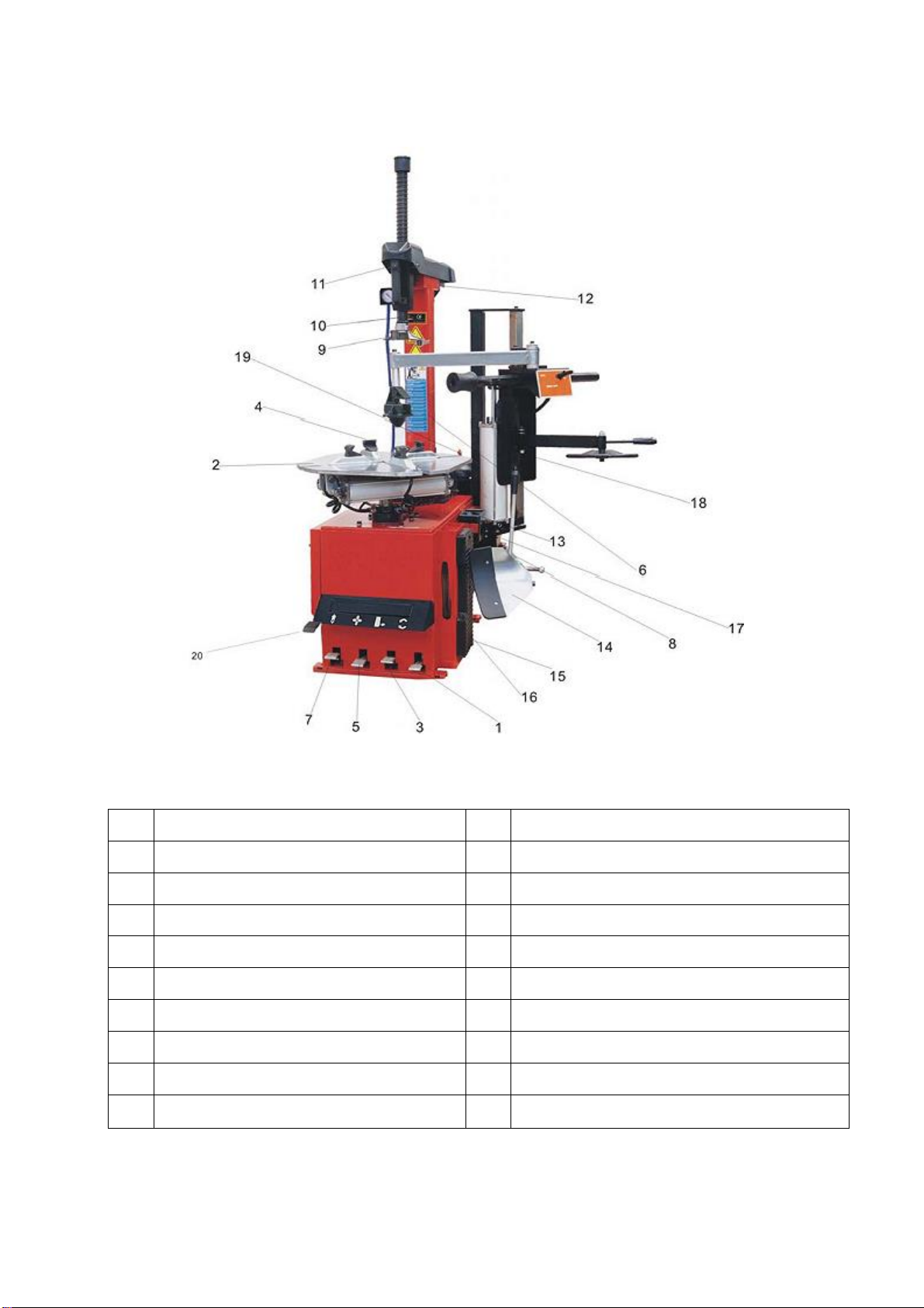
11. How the device is used. ........................................................................................................ 77
.................................................................................................................................................... 7
12. Preparing for use. ................................................................................................................. 77
.................................................................................................................................................... 7
13. Instructions for use................................................................................................................ 78
.................................................................................................................................................... 7
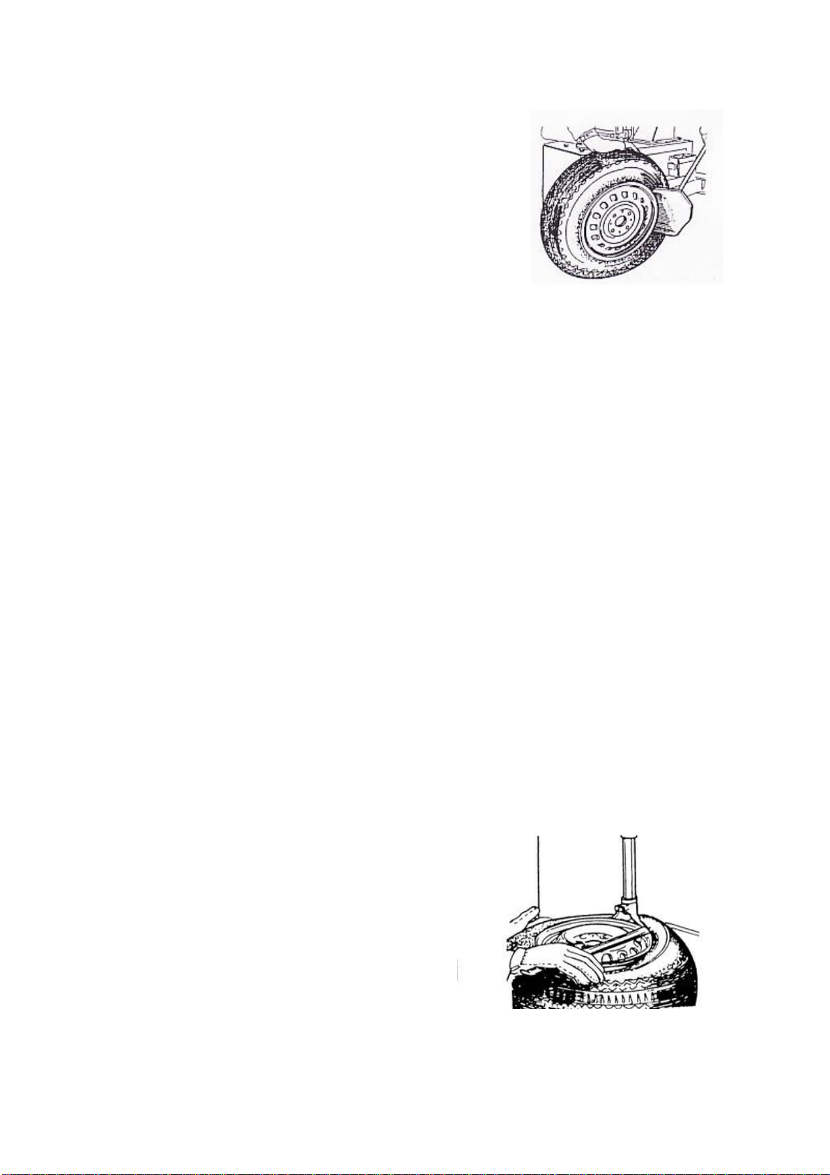
13.1 Loosening the tyre edging ................................................................................................ 88
................................................................................................................................................ 8
13.2 Tire....................................................................................................................8crimping 8
................................................................................................................................................ 8
13.3 Removing the tyre ........................................................................................................... 89
................................................................................................................................................ 8
13.4 Tyre assembly ..................................................................................................................... 99
.................................................................................................................................................... 9
13.4.1 Checking the tyre and wheel rims. Fig. 9 ..........................................................................
99.......................................................................
9
13.4.2 Tyre assembly .............................................................................................................910
................................................................................................................................................ 9
13.5. Pumping a threadless wheel (without the use of a special device for pumping heatless tyres)
...............................................................................................................................................1010
.................................................................................................................................................. 10
13.6 Pumping of driverless tyres (using a device for this type of tyre) .........................................1011
.................................................................................................................................................. 10
14. Storage..............................................................................................................................1112
.................................................................................................................................................. 11
15. Maintenance.......................................................................................................................1113
.................................................................................................................................................. 11

3
Warning
This manual is necessary for proper operation and maintenance of the device. Before starting
work, it is imperative that you read this user manual. Please keep this manual carefully so that you can
use it at any time if necessary.
1. Introduction
The mounting machine is designed for removing and putting on tires.
Note: Use only as intended. The manufacturer shall not be liable for damages resulting from the misuse
of the device as specified in this manual.
2. General safety rules
The device may only be operated by a person with relevant experience who is authorised to use it. The
manufacturer shall not be liable for damages resulting from changes in the device that have not been
agreed with him. Such equipment is no longer covered by the warranty. If one of the components of
the device is damaged, replace it according to the spare parts list. (Note: The warranty is valid for 12
months from the date of purchase of the product.) The manufacturer is not responsible for interference
with the device that has not been agreed with him in advance, especially in the event of interference
with electrical installations.
All work carried out on the electrical installation may be outsourced only to qualified personnel!
3. Technical data
Rim size (outer mounting) 10"-21" (outside)
Rim size (internal mount)12"-24" (internal) (operating pressure 8-10 bar)
Max wheel diameter 1040 mm (41')
Max tyre width 355mm (14')
Max cut-off pressure
(at 1 Mpa air pressure) 2500Kg
Operating pressure 8-10 bar
Power 110V (1ph)/ 220V (1ph) / 380V (3ph)
Engine power 1.1KW (1.5Hp)/ 0.75KW (1Hp)
Maximum torque (table)1078Nm (110Kg.m)
Total size 96X76X103cm
Noise level <75db
4. Transport
Transport only with a forklift. According to Figure 1 Fig. 1

4
5. Unpacking
To unpack the machine, remove the steel strips first and remove the box. Check for missing parts. In
cases of doubt, please contact the service before installing the device.
6. Workplace
The selected workplace should meet health and safety requirements, have access to electrical power
supply and air source as described in the manual. Adequate air circulation should be ensured in the
room so that the machine can function smoothly. Position the device in the working position while
retaining minimum wall spacing (see Figure 2). When installing the device in the open, place the device
under a shed to protect against rain and sunlight.
Warning: The engine device must not be operated in an explosive atmosphere.
Fig. 2

5
7. Device Description
1
Rotation pedal
2
Stage
3
Break-off pedal
4
Table jaw
5
Brush clamp pedal
6
Column
7
Column tilt pedal
8
Arm of the carer
9
Head
10
Vertical frames
11
Clamping bracket
12
Horizontal arm
13
Box
14
The paw of the de-super
15
Rubber resistance cap
16
Fitter bucket
17
Sączek
18
Auxiliary arm 006 (model 505f)
19
Tank (optional)
20
Pumping pedal (optional)
Note: The 19.20 instrument from the table above used when using the tireless
configuration device.

6
8. Installation method
Columns : Fig. 4
1). Prepare the necessary tool
2). Insert the column (1, Fig. 4)
into the square opening of the device (2,
Fig. 4), push the airline (3, Fig. 4)
through the hole in the column.
3). Insert the tilt cap (13, Fig. 4)
into theretainingcover (7, Fig. 4) screw in
with ascrew (14, Fig. 4) and acap (gasket)
(15, Fig. 4)
4). Insert the screw (17, Fig. 4)
into the opening of the column and connect
to the cylinder pin, attach with the
samesnap nut.( 16, Fig. 4)
5) Unscrew the two screws (4, Fig.
4)of the left cover (6, Fig. 4), then open
thecover. Connect the air hose (3, Fig. 4)
from the column to the five-outlet valve
connector.
6) Attach the plastic cover(9, Fig.
4)with two pins (10, Fig. 4).
7) Attach the rear plastic cover
(11, Fig. 4) tothe column with a
screw (12, Fig. 4).
9. Pneumatic connector:
Fig. 5
1) Release the pedal (5, Fig. 3) to avoid unexpected
opening of the stagejaws, and to avoid injury as a result of
an accident.
2) If necessary, connect the pumping gun to the cap. (Fig.
5)
3) Connect the installer to the compressed air network with
an air hose with a hole diameter of 7-8 mm and a
recommended air pressure of 8-10 bar.
4) The pressure must not exceed 10 bar, otherwise the
device is not subject to warranty.
Note: Compressed air pressure must not exceed 10 bar. In
the case of a pressure greater than 10 bar, it is asked to
install a pressure control valve.
10. Electrical connector
Before attaching the device, make sure that the characteristics of the electrical installation meet the
requirement of the device contained in the information plate.
Proper grounding is important. The electrical system shall be equipped with a safety switch with
differential protection set to 30A.

7
Warning: The rated power of the mounting device is indicated on the back of the unit panel. Please
check the voltage. All work carried out on the electrical installation may be outsourced only to qualified
personnel.
The manufacturer is not responsible in case of non-compliance with the rules of conduct contained in
the instructions.
Note:
Keep your hands and other parts of your body away from moving parts of the tire assembly.
Do not wear pendants, bracelets or loose clothes when using the device.
Obliterated or missing labels should be replaced immediately with new ones.
Keep the labels in the operator's sight.
11. How the device is used.
The control devices are shown in Figure 3, they consist of:
- clamping bracket (11), used to lock and unlock the vertical arm (10) and the horizontal arm(12).
Lifting head 2-3 mm.
- Column tilt pedal (7), allowing you to tilt the column(6) backwards.
- jaw clamp pedal (5), allowing you to close and open four jaws (4) on the Stage.
- rim break pedal (3), used to control the paw of the carer (14)
- rotation pedal (1), allowing you to rotate theStage (2) clockwise and vice versa.
12. Preparing for use.
After folding the device, make sure it's working. Fig. 6
1) Press the rotation pedal (1, Fig. 3), the Stage (2,
Fig. 3) should startrotating clockwise. Release the
pedal, the table should start rotating
counterclockwise.
2) Lower the break arm with your hands (8, Fig. 3)
and then press thepedal (3, Fig. 3) the break arm
should close.
3) Press down on the pedal (5, Fig. 3) to the end to
open the four jaws: press again, the barks should
be at rest: repeat the action severaltimes, the
barks should close.
4) Press the pedal (7, Fig. 3), the column will tilt to the resting position. Repeat the action , the
column returns to the working position.
6
5) Press the button on the handle (11, Fig. 3), horizontal arm(12, Fig. 3) and vertical arm(10,
Fig. 3), willlatch. Meanwhile, the head will automatically lift about 2-3mm from the rim edge:
repeat the action,the horizontal arm (12, Fig. 3) and the vertical arm (10, Fig. 3) will be
released.
6) Press the air meter trigger to release the air flow from the nozzle.
13. Instructions for use Fig. 7

8
Warning: Before starting work, make sure that all weights are removed
from the rim.
13.1 Loosening of the tyre edging
Be careful when loosening the tyre edging. Pressing the pedal
of the paw of the caresser, will trigger with great force the arm of the
carer, which can threaten objects located within the device.
1) Drain the air completely from the tire, remove the safety
valve cap;
2) Close the four jaws on the Stage to avoid problems during
the operation. When the jaws are open they can injured the hands so it is forbidden to
touch the circumcision of the tire when loosening it.
3) Open the rim break arm with your hands with movement outwards., place the tyre opposite
the support pad (15, Fig. 3) Attach the shovelto the rim at about 10mm from its edge, as
shown in Figure 7.
Note: Place the shovel in front of the rim.
4) Press the pedal(3, Fig. 3)to insert the shovel (14) between the rim and the tire. Repeat
the above action around the tyre on both sides of thewheel until thetyre is completely
separated.
13.2 Tyre crimping
1) Apply weights to the wheel rim;
2) Lubricate the tyre foot;
3) Press the pedal (7, Fig. 3), the column (6, Fig. 3) will set to the starting position.
4) Secure the wheel rim on the Stage from the inside or outside.
Under no circumstances should you put the cancer under the wheel when pressing the rim.
Place the tire in the middle of the Stage.
Make sure that the wheel is securely secured by four jaws.
a- clamping of the rim from the outside (tires 10"-20" inch)
Set the jaw clamp pedal (5, Fig. 3) in the intermediate position, set four barks. Place the wheel on
the Stage and press the jaw clamp pedal until the wheel clamps through the barks.
b- clamping of the rim from the inside (tires 12"-24" millimeter)
Close the four barks first by pressing the jaw clamp pedal to the end(5, Fig. 3). Place the wheel
on the Stage and press the pedal. The jaws will then open and clamp the rim.
13.3 Removing the tyre
Fig. 8
1)Place the horizontal arm (12, Fig. 3) on the column in the working position.
Do not bring your hands closer to the rim while the
clamping frame is in the working position to avoid crushing
2)Lower the vertical frame (10, Fig. 3) until the
head(9, Fig. 3) comes into contact with the upper edge of
therim. Lock the vertical frame with the clamping bracket
(11, Fig. 3). The head will automatically turn up to about
2 mm –3 mm from the rim.
3) Using the mounting bucket(16, Fig.
3),introduced between the tire foot and the front part
ofthe head(9, Fig. 3),move the foot over the wedge part
of the headas shown in Figure 8.
Note: If there is a wind in the tyre, it is recommended to keep the valve 10 cm to the right of
the head so as not to damage the wind.

9
Holding the mounting bucket (16, Fig. 3) in the position according to Fig. 8 turn the Stage
clockwise, constantly pressing the pedal (1, Fig. 3) until the tire completely disemmbs the rim.
To avoid injury, keep your hands and body parts as far away from the table as possible when
it rotates.
Note: The footer tends to slide off the head. To avoid this, you should first turn the table about
1~2 cm counterclockwise, holding the spoon in the position shown in Figure Fig. 8.
4) Remove any wind
5) Repeat step 3) on the other side of the wheel.
6) Press the pedal(7, Fig. 3)to flip the column (6, Fig. 3) to the resting position. Remove the
tyre from the rim.
13.4 Tyre assembly
13.4.1 Checking the tyre and wheel rims.Fig. 9
Note: Make sure that the tyre is the same size as the wheel rim,
this will prevent the tyre from breaking when it is pumped and
fixed.
Make sure:
- The tyre is not defective. Do not put the defective tyre on the
rim.
- Check that the rim is not dismedged and dislocated.
Remember: Especially with aluminum rims, spraining
often causes internal micro-chers that are not visible to the
naked eye, but disqualify the rim and are a source of accident
risk when pumping.
- The diameter of the tyre must correspond to the diameter of the rim.
Remember: The rim diameter is stamped on the rim, while the tyre diameter is indicated on the side
of the tyre. Never put a tyre on the rim if the actual diameters cannot be determined.
.
13.4.2 Tyre assembly
1) Lubricate the edges of the tyre with the rim of the grease.
2) Tighten the rim as specified in the "Rim clamp" section
3) Position the horizontal arm (12, Fig. 3) to the working position. Do not touch the rim with
your hands to avoid an accident.
4) Place the head with your hands (9, Fig. 3) above the rim edge. Press the horizontal arm
(12, Fig. 3) and the vertical arm (10, Fig. 3) as described in thesection "dismantling the tire" - step 2.
Remember: When working frequently with rims of the same diameter, you do not need to re-
position the head.
Instead, move the horizontal arm together with the clamped vertical arm.
5) Guide the tire with your hands so that the foot passes under the previous part of the head
and slides over the edge of the rear part of the head. (Fig. 9)
Note: If the tyre does not have a inner pole, position the rim so that the hole under the air valve
is in a position at 90 degrees relative to the head.
Hold the rim edge of the tyre with your hands. Press the pedal (1,Fig. 3 )to rotate the Stage
clockwise. Continue until the full wheel rim sinks in
To avoid personal injury, keep your hands away from mobile parts of the device.
6) Wsadź dętkę
7) Repeat the above steps for the other side of the tyre. Press the pedal (7, Fig. 3) when the
tyre isfully mounted, put the column to rest.
8) Press the pedal (5, Fig. 3), remove the tire from the Stage.
Remember: The Stage should rotate clockwise both when removing the tyre and putting it on. Rotating
in the opposite direction is only useful to correct some error during operation.

10
13.5. Pumping of the heatless wheel (without the use of a special device for pumping
heatless tyres)
Important: Fig. 10
Tire filling steps are dangerous, be careful,
follow the instructions.
A tyre burst can cause serious injury and even
death to the operator.
The device has a decompression valve that
prevents the pressure from exceeding the 3.5bar
value in the assembly unit. However, there is still a
risk of tyre bursting. Please do not underestimate the
danger.
The wheel may be breakinge if:
1) The dimensions of the tyre and rim are not the same.
2) The rim or tire is damaged.
3) During the pumping station, the permitted pressure was exceeded [tyre manufacturer's
carna
4) I do not follow the instructions.
Order of pumping operations:
1) Unscrew the valve cap.
2) Connect the gun tip to the tire valve by moving the lever to the "UP" position. Make sure
that the tip is completely adjacent to the valve.
3) Make sure that the diameters on the rim and tire match.
4) Make sure the rim and tire have been lubricated enough, Ew. Improve.
5) Inflate the tyre with short doses of compressed air. Simultaneously control the pressure on
the gun pressure gauge. Do this particularly carefully with a wealing rim that protects the
tyre foot.
6) Continue pumping, paying attention so as not to exceed the pressure specified by the
manufacturer. When the correct pressure is reached, remove the tip from the valve and
screw on the cap.
Remember:
Do not exceed the pressure indicated by the manufacturer during pumping.
When pumping, keep your hands and face as far away from the tire as possible.
This should only be done by a person trained for this purpose.
13.6 Pumping of heatless tyres (using a device for this type of tyre)
(1) The device for pumping heat-free tyres shall be used during rim application and pumping
operations by means of a special pump.
2) Disconnect the device from the power source.
3) Before starting work, check the device.
- Press the pumping pedal, which is located under the left cover of the box(position 1, Fig.
26). The pump head should start blowing air.
- Press the pumping pedal downwards(position 2, Fig. 26) From the four clamping sliders
should start to flow a strong airflow.
4) Rim fixing and pumping NOTE: THE WHEEL MAY
EXPLODE WHEN:
a. The rim diameter does not coincide with the tyre
diameter.
b. The rim or tyre is damaged. Note: Before any
installation, make sure that the assembly plant is
disconnected from the power source.
c. If the pressure exceeds the suggested value when the
rim is placed. Fig. 26

11
d. The tyre is pumped at a higher pressure than recommended by the manufacturer.
e. The operator does not comply with the required safety standards.
5) Wind tires
(a) . Unscrew the valve.
B. Connect the tip to the tyre valve while making sure it is tightly coupled.
c. Make sure that the diameters on the rim and tire match.
d. Make sure that the rim and tire have been sufficiently
lubricated, Ew. Improve
That. Press the pedal halfway down to start pumping air.
F. Often release the pumping pedal to check the pressure
on the pressure gauge. Inflate the tyre with short doses until
the desired pressure is obtained
Fig. 27
6) . Pumping of heatless tires.
Note: When pumping heatless tires, the wheel must be
fixed from the rim sirotka.
a) Unscreed the cap from the valve
b) Attach the pump to the valve, making sure that it is properly connected.
c) Check again that the rim diameter coincides with the diameter of the wheel.
d) Check that the rim and tyre are sufficiently lubricated, or correct them.
e) Press the pedal halfway down
f) If the foot does not slip into the rim, lift the tyre with your hand until the upper foot
rests against the rim, then press the pedal down.
g) Release the tyre and lift the foot slightly on the pedal so that it can return to the
intermediate position, pump the tire until the required pressure is reached.
Note::
1) Follow the instructions in the manual to avoid an accident.. Improper handling of the device
can result in serious injury and even death of the device operator. Under no circumstances
exceed the pressure limit of 3.5 bar when seating the rim and pumping the tire.
2) If a pressure greater than the above is required, remove the tyre from the mounting device
and continue pumping the wheel in a specially designed cage. NEVER exceed the tyre
manufacturer's pressure.
3) Keep your hands and other body parts away from the inflated tire.
4) The device can only be operated by qualified personnel.
14. Storage
If the appliance is not to be used for an extended period of time, disconnect it from the electrical
supply and the air source. Lubricate all parts that require it: slider, slider hole, horizontal arm slot. Empty
the box of oil and water, cover with a plastic cover to avoid contamination of the device.
11
15. Maintenance
Note: All maintenance may only be carried out by qualified personnel after the device plug
has been previously disconnected from the mains.
1) Disconnect the device from the mains.
Fig. 11
2) Disconnect the air source.
Follow the instructions:

12
-Clean the machine regularly after each use. Clean the Stage with detergent at least once a week and
lubricate the sliders and jaws.
- Empty the air filter from the water once a day to ensure that the cylinder is working.
At least once a month, check the oil level in the hydraulic unit. If necessary, replenish the oil condition
using: SAE30#, press the pedal 5-6 times to lock the tire, check that the oil in the hydraulic unit flows
freely, press down twice each time, lower the oil drop, tighten the screw (E) regulating the oil injection
with a screwdriver.
To extend the life of the device, maintain it systematically by following the instructions, neglect of the
device can lead to problems with its operation and damage to the body of the operator and people
nearby.
Warning: Before the above steps, disconnect the device from the mains and the air source,
press the rim break pedal 3~4 times to release compressed air from the device. (Fig.11)
Damaged parts should be replaced by qualified personnel with spare parts proposed by the
manufacturer
Note: After the first 20 days of use, tighten the jaws with clamping screws B. (Fig. 12)
Note: If you lose power, check that the strap is clamped. To do this, remove the left part of the housing
by unscrewing the screws. Tighten the strap with adjustable screws located on the motor booster. (Fig.
13)
Warning: Disconnect the device from the mains and air source.
Note: To maintain the reliability of the jaws and rim break arm, follow the instructions.
1.Remove the left side of the cover by unscrewing the screws;
2.Loosen the valve silencers (a) which are part of the jaw clamping pedal and the rim break pedal(Fig.
14)
3.Clean the silencer with compressed air and replace it with the original silencer from the spare parts
list if necessary.
Fig. 12 Fig.13 Fig.14

13
16.Fault detection
Vulnerability
Cause
Help
The Stage rotates only in the
one page or not at all.
Faulty switch
Replace
Damaged belt
Replace
Engine malfunction
Check cables or cables:
Replace the engine if it is
damaged.
The problem with lowering and lifting
the jaws, jamming on the Stage.
Leakage from the air system
Check all parts of the air
system
Cylinder not working
Replace the cylinder
piston.
Worn jaws
Replace jaws
Destroyed cylinder handle
washers
Replace
The head touches the rim during the
operation.
The clamping plate is incorrectly
fitted or is inadequate
Replace or adjust.
Loose screws of the handle, the
plate must not tighten
Tighten the screws,
replace the plate.
The rim deferment arm and clamping
jaw do not return to their initial
position.
Faulty pedal spring
Replace
Tilting the rim works faulty.
Clogged silencer .
Clean or replace.
Faulty rim dust collector cylinder
gasket.
Replace
Vulnerability
The switch holder is not movable
Cause
1) It is not connected to an air source
2) Damage to the air duct prevents free air flow
3) The valve has been damaged
Help
1) Connect the air source while maintaining the required pressure;
2) Check the air edivion, replace the damaged wire and the joints;
3) Contact the service.

14
Dear Customer!
CASTEX thanks you and congratulates you on your purchase. Please note that a warranty of 12
months from the date of purchase is provided for the product you purchased. This Warranty Card
is only valid with the seller's proof of sale or the seller's signature and stamp. As part of the
warranty period, all defects will be reassanced free of charge, provided that they are caused by
manufacturing or technical defects of the product and when the device has been used for its
intended purpose and with the requirements of the user manual. Please read the detailed
warranty conditions.
This warranty does not exclude or limit the buyer's rights arising from the non-conformity of the
goods with the contract.
Warranty card number ................................
FILLED BY SELLER
Date of sale of the product (in the absence of an entry, a proof of sale must be attached)
Product name and symbol
Customer*)
Customer Address
Seller's stamp and signature (in the absence of a stamp and signature, the Guarantor, i.e. CASTEX, is
considered to be the Seller
Anna Bednarz on the basis of proof of sale)
Customer Signature
Please note that without completing all of the above points, the warranty card is void!
Service Repairs
Lp.
Description of the repair
Date, signature and stamp

15
*) The owner of the equipment making claims under the guarantee is obliged to
provide personal data in accordance with Art. 23 paragraph 1 point.3 of the Personal
Data Protection Act of 29.07.1997, as amended. D
size I
COLLECTION PROTOCOL
I hereby confirm the reception of the device according to the following specifications
on........................
The received device is complete and in accordance with the order.
Order specification
Pieces
1

16
2
3
4
5
Date Stamp and signature of the buyer
….......................................................................................................................................
Receipt for Guarantor of receipt of guarantee card NO ; ............................
Warranty Card No-........................................ Serial No. -................................................
Name, Surname, buyer's address, phone number ............................
Date of sale .................................
I confirm receipt of the GOODS and the warranty card, which I have read and accepted the
warranty conditions:
.....................................................................
Date and legible signature of the
buyer
For distance purchases, this voucher must be returned to the guarantor within 14 days from the
date of purchase of the device.
Warranty Terms
1. CASTEX hereinafter referred to as the Guarantor provides a guarantee for the smooth
operation of the above-called equipment within 12 months from the date of purchase.
This guarantee covers:

17
a) Spare parts
b) Design elements of the device
c) Arrival of an authorized CASTEX service technician to correct defects.
2. The warranty for the device, sold outside the RP, covers only spare parts, unless otherwise
specified.
3. The warranty does not cover defects caused by:
a) wear, abuse, overload, improper installation or failure to carry out regular
maintenance.
b) customer's negligence or conduct inconsistent with the instructions in the user's
manual.
c) failure to comply with the operating instructions, failure to comply with the frequency
of maintenance work specified by the manufacturer, poor power source (rotating
field, rated voltage, etc.) or improper use (overload, installation outside the closed
building, technical changes) or improper installation.
d) Damage to the equipment due to fire, flood, lightning or other natural disasters, wars,
civil unrest, accidents, power grid surges, improper electrical connections, mechanical
damage to varnish, corrosion caused by pressurised washing or discontinuation of
maintenance or lack of purification.
4. CASTEX is not responsible for damage to the equipment during transport (in case the
transport is not outsourced by CASTEX). The Recipient is obliged to check the visual
condition of the device and in case of defects the Recipient is obliged to immediately report
this fact to CASTEX or the Distributor. Please write down the damage report with the
Courier delivering the device at the time of delivery.
5. In the event of damage to the equipment during the warranty period, the Guarantor will
provide a free repair or replacement of the damaged parts after checking the validity of
the complaint. The repair time shall not exceed 30 days from the date of written or e-mail
notification of the failure.
6. Specialist repairs requiring components to be brought in from abroad: in this case, the
repair time can be extended by another 30 working days. The method of repair is
determined by the Guarantor.
7. Devices that require adjustment or maintenance from time to time, as described in the
device manual, may be performed by the User, unless otherwise stated in the manual.
8. Any damage caused by the operation and maintenance of a device not in accordance with
the instructions, improper transport, operation of the device in climatic conditions not in
accordance with the instructions or other causes caused by the User may be repaired at
his expense.

18
9. In the event of an unjustified complaint, the User shall bear the costs incurred by the
Guarantor, which consist of: commuting, the cost of technical inspection, the cost of the
listed components, the cost of round-trip courier transport.
10. The device owner is responsible for all maintenance activities of the device.
11. Devices fitted with electronic components shall be stored as well as used in rooms where
the air temperature is between + 8 and 25 degrees C.
12. CASTEX reserves the right to refuse free service in the absence of a warranty card.
13. In case of purchase of the device/equipment at a distance, the Buyer undertakes to send
back to the Seller/Guarantor page III - the collection protocol and receipts for the
Guarantor. In case of non-receipt of the protocol and receipt, the Guarantor may refuse
to provide a free service.
14. Any complaint must first be submitted to serw[email protected] or via the
https://castex.pl/formularz-reklamacyjny/ website to contact you. The application must
include data such as the type of device, model, applicant's details, date of purchase and
FV number, and the address of the place where the device is located.
Table of contents
Other Castex Tyre Changer manuals