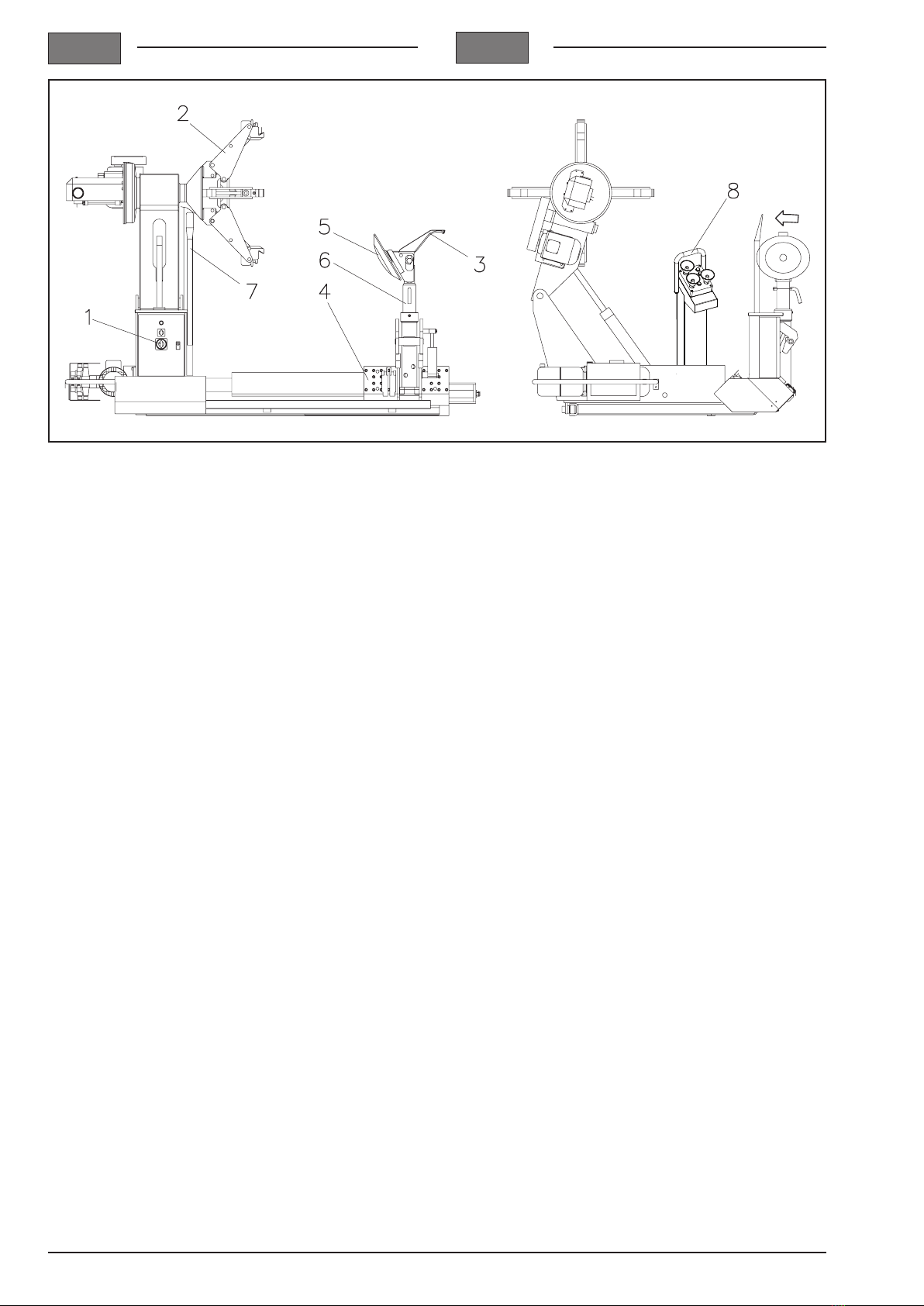
Cormach SUPER VIGOR 2450 User manual

SMONTAGOMME
TYRE CHANGER
SUPER VIGOR 2450
02/2010
MANUALE USO E MANUTENZIONE
USE AND MAINTENANCE MANUAL
IT
UK


IGB
3
ISTRUZIONI ORIGINALI
INDICE
1 DESTINAZIONE D’USO
2 NORME GENERALI DI SICUREZZA
3 TRASPORTO
4 DISIMBALLO
5 INSTALLAZIONE
6 MONTAGGIO E MESSA IN SERVIZIO
7 ACCANTONAMENTO
8 ROTTAMAZIONE
9 DATI TECNICI
10 CARATTERISTICHE D’IMPIEGO
11 DATI DI TARGA
12 MANUTENZIONE ORDINARIA
13 TABELLA RICERCA EVENTUALI
INCONVENIENTI
14 ISTRUZIONI PER L’USO
15 MEZZI ANTINCENDIO
PER ASSISTENZA TECNICA
16 MANUTENZIONE STRAORDINARIA
17 SCHEMI ELETTRICI/IDRAULICI
TRANSLATION OF ORIGINAL INSTRUCTIONS
CONTENTS
1 INTENDED USE
2 GENERAL SAFETY RULES
3 TRANSPORT
4 UNPACKING
5 INSTALLATION
6 ASSEMBLY AND COMMISSIONING
7 LAY-OFFS
8 SCRAPPING
9 TECHNICAL DATA
10 SERVICE CHARACTERISTICS
11 NAMEPLATE DATA
12 ROUTINE MAINTENANCE
13 TROUBLESHOOTING TABLE
14 INSTRUCTIONS FOR USE
15 FIRE-FIGHTING EQUIPMENT
FOR THE TECHNICAL SERVICE
16 EXTRAORDINARY MAINTENANCE
17 ELECTRIC/HYDRAULIC SYSTEM DIAGRAMS
I-GB Cod. 4-328371A - 02/10 - REV.2

IGB
6
1
1 Interruttore generale
2 Mandrino
3 Utensile
4 Carrello porta utensile
5 Disco stallonatore
6 Braccio porta utensile
7 Leva alzatalloni
8 Manipolatore
1 Master switch
2 Turntable
3 Tool
4 Tool-holder carriage
5 Bead breaker disk
6 Tool-holder arm
7 Bead lifting lever
8 Control lever

IGB
7
Dimensioni d’ingombro
2
Overall dimensions

IGB
8
1 DESTINAZIONE D’USO
Il presente libretto costituisce parte integrante del
prodotto. E’ nostra intenzione fornire al proprietario e
IN OPERA, l’USO (SICUREZZA D’USO) e la MANU-
TENZIONE dello smontagomme per autocarro Mod.
SUPER VIGOR 2450.
CONSERVAREQUESTOLIBRETTOCONCURAENEI
PRESSI DELLA MACCHINA PER OGNI ULTERIORE
CONSULTAZIONE DA PARTE DEGLI OPERATORI.
Lo smontagomme Mod. SUPER VIGOR 2450 è stato
realizzato per essere utilizzato nello smontaggio e
montaggio di pneumatici d’autocarri, trattori agricoli e
macchine operatrici sui relativi cerchi.
La macchina può operare su gomme da 14" a 56", con
diametro massimo della di ruota 2450 mm.
Tutti i comandi sono ottenuti mediante funzioni idrau-
liche/elettriche, attraverso una razionale e funzionale
consolle comandi disposta su di un apposito braccio
snodato che permette il suo utilizzo in tutte le posizioni
di lavoro.
ATTENZIONE
Quest’apparecchio dovrà essere utilizzato solo al-
l’uso per il qual è stato espressamente concepito.
OgnialtrousoèdaconsiderarsiIMPROPRIOe quindi
IRRAGIONEVOLE.
Il costruttore non può essere considerato responsabile
per eventuali danni causati da usi impropri, erronei ed
irragionevoli.
1 INTENDED USE
This manual constitutes an integral part of the product.
It is intended to provide the owner and operator with
effective, safe instructions for the COMMISSIONING,
USE (SAFETY IN USE) and MAINTENANCE of the
Mod. SUPER VIGOR 2450 truck tyre changer.
CONSERVE THIS MANUAL WITH CARE, CLOSE TO
THE MACHINE, FOR ANY FURTHER CONSULTA-
TION BY THE OPERATORS.
The Mod. SUPER VIGOR 2450 tyre changer is con-
structed for use to remove the tyres of trucks, agricultural
tractors and earthmoving machines from, and mount
them on, the relative wheel rims.
The machine is able to handle tyres from 14” to 56”,
with maximum wheel diameter 2450 mm.
All functions are electro-hydraulically powered, with
control by means of a rational, function control console
on a special articulated arm which can be used in all
working positions.
CAUTION
This machine must only be used for the purpose for
All other uses must be considered IMPROPER and
thus UNREASONABLE.
The manufacturer cannot be considered responsible
for any damage caused by improper, incorrect or un-
reasonable use.

IGB
9
2 NORME GENERALI DI SICUREZZA
L’uso dell’apparecchiatura è consentito solo a personale
appositamente addestrato e autorizzato. Ogni e qual-
preventivamente autorizzate dal costruttore sollevano
quest’ultimo da danni derivati o riferibili agli atti suddetti.
La rimozione o manomissione dei dispositivi di sicurezza
comporta una violazione delle NORME EUROPEE sulla
sicurezza sul lavoro.
L’uso della macchina è consentito solamente in luoghi
privi di pericoli di esplosione o incendi.
DISPOSITIVI DI SICUREZZA
- Per aprire lo sportellino del quadro elettrico bisogna
prima sconnettere la corrente elettrica mediante apposito
interruttore, come previsto dalle normative CEE.
- La disposizione logica dei comandi evita eventuali
pericolosi errori da parte dell’operatore.
- Fungo d’emergenza per l’interruzione dell’alimenta-
zione della macchina
- Tutti i comandi situati sul manipolatore si interrompo-
no rilasciando il comando stesso (comando a uomo
presente)
ATTENZIONE
E’ tassativamente vietato manomettere o togliere
ogni dispositivo di sicurezza
ATTENZIONE
Eseguire con attenzione le operazioni di montag-
gio e installazione descritte. L’inosservanza di tali
raccomandazioni può provocare danneggiamenti
alla macchina e pregiudicare la sicurezza dell’ope-
ratore.
ATTENZIONE
Durante le operazioni di lavoro e manutenzione rac-
cogliere i capelli lunghi e non indossare abiti ampi
o svolazzanti, cravatte pendenti ,collane, anelli, che
possono essere presi da parti in movimento.
2 GENERAL SAFETY RULES
The machine must only be used by specially trained and
manufacturer in advance relieves the manufacturer of
responsibility for any damage deriving from or traceable
to such procedures. Removal of or tampering with the
safety devices is a breach of EUROPEAN REGULA-
TIONS on safety at work.
The machine may only be used in places free from
SAFETY DEVICES
- To open the door of the control panel, the electricity
as required by EEC standards.
- The logical layout of the controls avoids any hazardous
errors on the part of the operator.
- Mushroom-head emergency button to cut off the power
supply to the machine.
- All functions controlled by the control levers are disabled
when the control is released (dead-man principle).
CAUTION
Tampering with or removing any safety device is
absolutely forbidden.
CAUTION
Carry out the assembly and installation operations
described with care. Failure to comply with these
recommendationsmaycausedamagetothemachine
and put the operator at risk.
CAUTION
Duringworkandmaintenanceprocedures,keeplong
clothes, hanging ties, necklaces or rings which may
become caught on moving parts.

IGB
10
3 TRASPORTO
Tutti i movimenti della macchina ancora imballata devo-
no essere effettuati tramite un transpallet o un carrello
elevatore, inforcando le pale di questi nelle apposite
feritoie poste sotto all’imballo o alla cassa.
ATTENZIONE
Non è consentito il sollevamento tramite gru o pa-
ranco della macchina imballata
ATTENZIONE
Prima di effettuare qualunque tipo di movimenta-
idonea a tale servizio.
Nel caso di macchina non imballata osservare le se-
guenti avvertenze:
- Proteggere gli spigoli vivi alle estremità con materiale
idoneo (Pluribol o cartone).
MOVIMENTAZIONE / IMMAGAZZINAMENTO DELLA
MACCHINA
Per movimentare la macchina priva di imballo utilizzare
esclusivamente i punti di ancoraggio.
Le macchine imballate vanno immagazzinate in luogo
asciutto e possibilmente aerato.
Disporre gli imballi a distanza utile per consentire una
facile lettura delle indicazioni posti sui lati dell’imballo.
3
3 TRANSPORT
While the machine is still in its packaging, it may only be
handled using a pallet truck or a fork-lift truck, inserting
the forks in the slots provided underneath the packag-
ing or crate.
CAUTION
The machine in its packaging must not be lifted us-
ing a crane or hoist.
CAUTION
Before handling the machine in any way, check that
the lifting equipment is of suitable capacity.
If the machine is not in its packaging, take the following
precautions:
- Protect the sharp edges at the ends with suitable mate-
rial (Pluribol or cardboard).
HANDLING / STORING THE MACHINE
When handling the machine without packaging, use only
the anchor points provided.
Machines in their packaging must be stored in a dry
place, with ventilation if possible.
Place the packs far enough apart to allow the informa-
tion provided on the sides of the packaging to be read
easily.

IGB
11
ATTENZIONE
Per evitare danneggiamenti non sovrapporre altri
colli sull’imballo.
E’assolutamentevietatoutilizzareappigli
impropri sui vari organi sporgenti della
struttura.
Temperatura dell’ambiente di stoccaggio dell’imballo:
-25° - +55° C
4 DISIMBALLO
Dopo aver liberato la macchina dalle protezioni esterne
poste per proteggere la stessa dai pericoli del trasporto,
assicurarsi dell’integrità dell’apparecchio controllando
che non vi siano parti visibilmente danneggiate.
Nel caso in cui si sono riscontrati dei danni all’apparec-
chio, o anche solo in caso di dubbio, NON UTILIZZARE LA
MACCHINA e rivolgersi a personale professionalmente
La scatola contenente gli accessori è
contenuta nell’involucro NON GETTARE
CON L’IMBALLAGGIO
Gli elementi dell’imballaggio (sacchetti di plastica, polisti-
rolo espanso, chiodi, viti, legni ecc.) non devono essere
lasciati alla portata dei bambini in quanto possibili fonti di
pericolo. Riporre i suddetti materiali negli appositi luoghi
di raccolta se inquinanti e non biodegradabili.
CAUTION
To avoid damage, never place other items on top of
the packaging.
Gripping the various projecting parts of
the structure in a manner not recommen-
ded here is absolutely forbidden.
Temperature of storage environment for machines in
packaging: -25° - +55° C
4 UNPACKING
After removing the external packaging provided to
protect the machine from damage in transit, check that
the machine is intact by examining all parts for visible
damage.
If damage is noted, or if just unsure, DO NOT USE
THE MACHINE and contact a skilled professional (your
dealer).
The box containing the accessories is
inside the packaging DO NOT THROW
THIS OUT WITH THE PACKAGING
Packaging materials (plastic bags, expanded polysty-
rene, nails, screws, pieces of wood, etc.) must never
be left within the reach of children since they are po-
tentially dangerous. Dispose of these materials at the
biodegradable.

IGB
12
5 INSTALLAZIONE
ATTENZIONE
Al momento della scelta del luogo di installazione
è necessario osservare le normative in uso della
sicurezza sul lavoro.
Ogni apparecchiatura deve essere installata su di un
pavimento stabile e rigido. Devono essere rispettati gli
spazi richiesti per il lavoro.
ATTENZIONE
Nel momento in cui l’installazione è eseguita in
luogo aperto è necessario proteggere la macchina
con una tettoia.
Condizioni ambientali di lavoro
- Umidità relativa: 40° — 95%
- Temperatura:0° — 45°
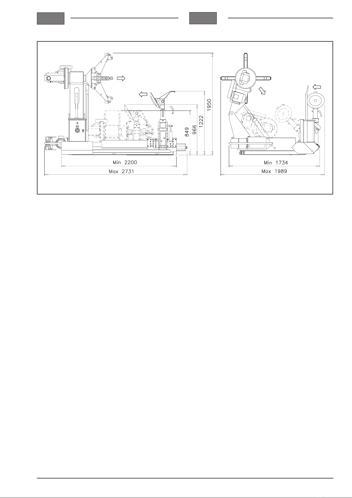
AREA D’INSTALLAZIONE
L’installazione della macchina necessita di uno spazio
utile di cm 517x635x285.
Dalla posizione di comando l’operatore è in grado di
visualizzare la macchina e l’area circostante.
Egli deve impedire in tale area, la presenza di persone
non autorizzate e di oggetti che potrebbero causare
fonte di pericolo.
La macchina deve essere montata su di un piano oriz-
zontale preferibilmente cementato o piastrellato.
Evitare piani cedevoli o sconnessi.
Il piano d’appoggio della macchina deve sopportare i
carichi trasmessi durante la fase operativa.
ATTENZIONE
viti e tasselli ad espansione solo se si utilizzano
ruote con peso superiore a 500kg.
PROCEDIMENTO DI POSA DEI TASSELLI
1 Forare con punta ø16 mm per una profondità di 80
mm.
2 Pulire il foro
3 Spingere i tasselli nel foro con piccoli colpi di martel-
lo.
4 Stringere i bulloni con chiave dinamometrica, tarata
a 45 Nm (se tale valore non è ottenibile, ciò è dovuto al
foro troppo grande o al calcestruzzo non consistente).
5 INSTALLATION
CAUTION
When choosing the installation site, comply with the
current regulations as regards safety at work.
The spaces necessary for work must be left.
CAUTION
If the machine is installed outdoors, it must be pro-
tected with a suitable shelter.
Working environment conditions
- Relative humidity: 40 — 95%
- Temperature: 0° — 45°
INSTALLATION AREA
An area of 517x635x285 cm is required for installation
of the machine.
From the control position, the operator has a good view
of the machine and the surrounding area.
He must keep unauthorised persons and objects which
might cause hazards outside this area.
The machine must be installed on a horizontal surface,
preferably on concrete or ceramic tile coverings.
Avoid loose or unstable surfaces.
The surface on which the machine is installed must
withstand the loads transmitted during operation.
CAUTION
and screw anchors only if wheels with weight in
excess of 500 kg are changed.
PROCEDURE FOR INSTALLING THE SCREW AN-
CHORS
1 Drill a hole 80 mm deep using a bit ø 16 mm
2 Clean the hole
3 Tap the screw anchors into the hole hitting them softly
with a hammer
4 Tighten the bolts using a torque wrench set at 45
Nm (if this value cannot be obtained, this is because

IGB
13
6 MONTAGGIO E MESSA IN SERVIZIO
Dopo aver liberato i vari componenti dall’imballaggio
e aver controllato lo stato di integrità e la mancanza di
eventuali anomalie, seguire le seguenti istruzioni per
provvedere all’assemblaggio dei componenti stessi
seguendo, come riferimento, le istruzioni qui di seguito
riportate.
Strumenti necessari all’installazione:
- n° 1 cacciavite
- n° 1 chiave esagonale da 13
Fissare la colonna portacomandi al basamento con le
Collegamento elettrico
Gliinterventisulla parte elettrica anche di
lieveentitàrichiedono l’opera di persona-
Nelle versioni standard il sistema di alimentazione della
macchina è TRIFASE + TERRA a 380V. o 220V.
La predisposizione della tensione della macchina è rea-
alimentazione non può essere realizzata all’utilizza-
tore, ma richiede l’intervento del personale profes-
di assistenza autorizzato.
Per l’alimentazione elettrica utilizzare un cavo con se-
zione minima di 4 mmq, 3 poli + terra da collegare ai
morsetti L1-L2-L3 del pannello elettrico.
morsettiera del quadro di comando, osservare le se-
guenti disposizioni:
- Controllare che la tensione di alimentazione sia corri-
spondente a 380 Volt (o 220 Volt).
del conduttore di terra.
- Controllare che a monte si trovi un dispositivo di in-
terruzione automatica contro le sovracorrenti dotato di
salvavita da 30 mA.
- Collegare il cavo all’apparecchio con la massima cura
in base alle norme vigenti.
Il dimensionamento dell’allacciamento elettrico va
eseguito in base alla potenza elettrica assorbita dalla
targhetta dati.
Il senso di rotazione della ruota, in marcia normale deve
di corrente nella spina di alimentazione.
Ogni danno derivante dalla mancata os-
servanzadellesuindicatedisposizioninon
sarà addebitabile al costruttore e potrà
causare la decadenza della garanzia.
6 ASSEMBLY AND COMMISSIONING
After unpacking the various components and checking
them for damage or any anomalies, follow the instructions
provided below to assemble the various components.
Tools required for installation:
- 1 screwdriver
- 1 13 spanner
screws.
Electrical connection
Even small jobs on the electrical equip-
mentmustbeperformedbyprofessionally
In standard versions, the machineís power supply system
is THREE-PHASE + EARTH at 380 V or 220 V.
The machine is pre-set in the factory for the voltage
Any change to the power supply voltage cannot be
staff, your dealer or authorised service centre.
The electricity supply lead must consist of a cable with
minimum gauge 4 mm2, 3 poles + earth to be connected
to terminals L1-L2-L3 of the control panel.
Before connecting the power supply wires to the control
panel terminal board, proceed as follows:
- Check that the power supply voltage is 380 Volts (or
220 Volts).
- Check the condition of the wires and that the earth wire
is present.
- Check that an automatic circuit breaker protecting
against overcurrents is located upstream of the machine
together with a residual current operated device (rated
at 30 mA).
- Connect the cable to the machine with the greatest
care, in accordance with the regulations in force.
The dimensions of the electrical connection must be
on the relative nameplate.
In normal operation, the wheel must turn clockwise;
otherwise, reverse two wires in the power supply plug.
Themanufacturer willnot acceptresponsi-
bility for any damage deriving from failure
to follow the instructions provided above,
which may also cause the guarantee to
become null and void.

IGB
14
7 ACCANTONAMENTO
In caso di accantonamento per un lungo periodo è ne-
cessario scollegare le fonti di alimentazione, svuotare
il serbatoio contenente il liquido di funzionamento, e
provvedere alla protezione di quelle parti che potreb-
bero essere danneggiate dalla polvere. Provvedere ad
ingrassare le parti che si potrebbero danneggiare in
caso di essiccazione.
8 ROTTAMAZIONE
Nel momento in cui si deciderà di non utilizzare più questa
macchina, si raccomanda di renderla inoperante aspor-
tando le parti elettriche, elettroniche, idrauliche e plasti-
che, poi rottamare il resto come materiale ferroso.
Il materiale elettrico (cavi) va rottamato come rame.
Si raccomanda di rendere innocue quelle parti suscettibili
di causare fonte di pericolo esempio:
serbatoio olio
motore elettrico
di smaltimento.
ATTENZIONE.
Sirammental’utilizzatorecheècomunque
tenuto a rispettare le leggi sulla ROTTA-
MAZIONE in vigore nel paese di utilizzo.
INDICAZIONI E AVVERTENZE SULL’OLIO
Smaltimento olio usato
Non gettare l’olio usato in fognature cunicoli o corsi
d’acqua; raccoglierlo e consegnarlo ad aziende spe-
cializzate per la raccolta e lo smaltimento.
Spargimento o perdite d’olio
Circoscrivere il prodotto fuoriuscito con materiale as-
sorbente, tipo terra o sabbia, poi sgrassare con solventi
evitando la formazione o la stagnazione dei vapori.
Precauzioni nell’impiego dell’olio
Evitare il contatto prolungato con la pelle.
Evitare la formazione o la diffusione di nebbie d’olio
nell’atmosfera.
Adottare quindi le seguenti precauzioni:
Evitare gli schizzi (usare indumenti appropriati e schermi
protettivi sulle macchine).
Lavarsi frequentemente con acqua e sapone; non uti-
lizzare prodotti irritanti o solventi
Non asciugarsi le mani con stracci sporchi o unti.
Cambiarsi gli indumenti se sono impregnati.
Non fumare o mangiare con le mani unte.
Utilizzare guanti resistenti agli oli minerali.
Usare gli occhiali, in caso di schizzi.
Usare grembiuli resistenti agli oli minerali.
Utilizzare aspiratori in caso di formazione di nebbie
d’olio.
7 LAY-OFFS
If the machine is to be out of use for a long period,
disconnect it from the power sources, empty the tank
which might be damaged by dust. Grease the parts
which might also be damaged if they dry out.
8 SCRAPPING
If the machine is to be decommissioned, it must be made
unusable by removing the electrical, electronic, hydraulic
and plastic parts; the rest must then be disposed of as
ferrous material. The electrical material (cables) must
be scrapped as copper.
Care must also be taken to make safe those parts which
might be potential dangers, such as:
electric motor
Consider the category of each item with regard to the
recommended disposal procedure
CAUTION
Users are reminded that in all cases they
are obliged to comply with the laws on
SCRAPPING in force in the country of
use.
ADVICE AND WARNINGS ON HYDRAULIC FLUID
-
sages or into watercourses; collect it and consign it to
specialised companies for collection and disposal.
Fluid leaks or spills
Limit the spread of the spilt material with absorbent ma-
terial such as soil or sand, then degrease with solvents,
preventing the formation or stagnation of vapours.
Avoid prolonged contact with the skin.
the atmosphere.
Take the following precautions:
Avoid splashes (wear suitable clothing or protective
screens on machines).
Wash yourself frequently using soap and water; do not
use irritant products or solvents.
Never dry your hands using dirty or oily ranges.
Never smoke or eat with oily hands.
Wear gloves resistant to oily minerals.
Wear goggles in case of splashes.
Wear aprons resistant to mineral oils.

IGB
15
Olio: indicazioni di pronto soccorso.
Ingestione: non è necessario nessun trattamento di
cura.
Aspirazione di liquido: in caso di vomito spontaneo,
trasportare il colpito d’urgenza all’ospedale.
Inalazione: in caso di forti inalazioni di forti vapori o
nebbie, potare il colpito all’aria aperta.
Occhi: sciacquare abbondantemente gli occhi con
acqua.
Pelle: lavare con acqua e sapone.
9 DATI TECNICI
- Alimentazione elettrica trifase: .......... 380 V. 50/60Hz
- Alimentazione elettrica trifase: .......... 220 V. 50/60Hz
RIDUTTORE MORSA
- Motore el.trif.4/2 poli B3 380/V 50/60Hz:1.25-1.8 KW
2° velocità
- Motore el.trif.4/2 poli B3 220/V 50/60Hz:1.25-1.8 KW
2° velocità
CENTRALINA IDRAULICA
- Motore el.trif.4 poli B14 380/220V 50/60Hz:...1.5 KW
1° velocità
- Motore el.trif.4/2 poli B14 380/V 50/60Hz:... 1.1-1.4 KW
2° velocità
- Motore el.trif.4/2 poli B14 220/V 50/60Hz:... 1.1-1.4 KW
2° velocità
- Larghezza:.......................................1730 ÷ 1990 mm
- Lunghezza:......................................2200 ÷ 2730 mm
- Altezza:...............................................................1950
- Peso: ............................................................ 1200 Kg
- Peso massimo ruota:.................................... 1300 Kg
- Capacità serbatoio olio:......................................litri 8
- Temperatura di utilizzo: ...........................0°C ÷ 45° C
- Campo umidità: .......................... 57% ÷ 95% a 40° C
10 CARATTERISTICHE D’IMPIEGO
...................118mm ÷ 760 mm
- Bloccaggio su cerchio senza prolunghe:..... 14" ÷ 36"
- Bloccaggio su cerchio con prolunghe:......... 34" ÷ 56"
- Diametro max. del pneumatico:...................2450 mm
- Larghezza max. del pneumatico: ................1220 mm
Swallowing: no treatment is needed.
Aspiration of liquid: in case of spontaneous vomiting,
take the affected person to hospital urgently.
Inhalation: if large amounts of strong vapours or mists
are inhaled, take the affected person into the open air.
Eyes: rinse the eyes with plenty of water
Skin: wash with soap and water.
9 TECHNICAL DATA
- Three-phase electrical power supply:. 380V 50/60 Hz
- Three-phase electrical power supply:. 220V 50/60 Hz
JAW GEAR MOTOR
- Three-phase electric motor 4/2 poles B3 380 V
50/60 Hz: 1.25-1.8 KW 2
nd speed
- Three-phase electric motor 4/2 poles B3 220 V
50/60 Hz: 1.25-1.8 KW 2
nd speed
HYDRAULIC POWER UNIT
- Three-phase electric motor 4 poles B14 380/220 V
50/60 Hz: 1.5 KW 1st speed
- Three-phase electric motor 4/2 poles B14 380 V
50/60 Hz: 1.1-1.4 KW 2nd speed
- Three-phase electric motor 4/2 poles B14 220 V
50/60 Hz: 1.1-1.4 KW 2nd speed
- Width: ..............................................1730 ÷ 1990 mm
- Length: ............................................2200 ÷ 2730 mm
- Height: .........................................................1950 mm
- Weight: ......................................................... 1200 Kg
- Maximum wheel weight: ............................... 1300 Kg
........................... 8 litres
- Operating temperature: ............................0°C ÷ 45°C
- Humidity range: .......................... 57% ÷ 95% at 40°C
10 SERVICE CHARACTERISTICS
.....................118 mm ÷ 760 mm
- Clamping on rim without extensions:........... 14" ÷ 36"
- Clamping on rim with extensions:................ 34" ÷ 56"
- Max. tyre diameter:......................................2450 mm
- Max. tyre width: ...........................................1220 mm

IGB
16
11 NAMEPLATE DATA
- CORMACH S.r.l.
via Mons. Pignedoli 2
42015 CORREGGIO (RE) ITALY
- Phone 0039-0522-631274 - fax 0039-0522-631284
- CE mark
- year of construction:
- model: SUPER VIGOR 2450
12 ROUTINE MAINTENANCE
-
eration, it is essential to comply with the manufacturerís
instructions with regard to cleaning and regular routine
maintenance.
CAUTION
Cleaning and routine maintenance must be carried
out by authorised personnel in accordance with the
MANUFACTURER instructions provided below:
Check that there is still grease in the reduction unit,
and add VANGUARD LIKO-3 or corresponding grease
if necessary.
CAUTION
-
ties different from those indicated may reduce the
machineís lifetime and impair its performance.
Clean all moving parts (jaw unit).
Keep the machine and the working area clean to prevent
IMPORTANT
The operator MUST NEVER vary the relief valve
trigger pressure value and MUST NEVER vary the
setting value of the pressure limiter.
Themanufacturerdeclinesallresponsibilityforinjury
or damage due to failure to follow this rule.
CAUTION
No maintenance work must be carried out until the
plug has been disconnected from the electrical
mains.
CAUTION
Never clean by blowing with compressed air.
11 DATI DI TARGA
- CORMACH S.r.l.
via Mons. Pignedoli 2
42015 CORREGGIO (RE) ITALY
-Tel. 0522/631274 - fax 0522/631284
- marchio CE
- anno di costruzione :
- modello: SUPER VIGOR 2450
12 MANUTENZIONE ORDINARIA
corretto funzionamento, è indispensabile attenersi alle
istruzioni del costruttore, effettuando la pulizia e la pe-
riodica manutenzione ordinaria.
ATTENZIONE
Le operazioni di pulizia e manutenzione ordinaria
devono essere effettuate da personale autorizzato
in accordo alle istruzioni del COSTRUTTORE di
seguito riportate:
controllare il livello dell’olio nel serbatoio; rabboccarlo
se necessario usando olio API CI S32 o suo corrispon-
dente.
controllare checisiaancoragrasso nelgrupporiduttore;e
aggiungerne se necessario usando grasso VANGUARD
LIKO-3 o suo corrispondente.
ATTENZIONE
Eventuali rabbocchi o cambi olio eseguiti con olio di
qualitàdiversadaquellaindicata,possonodiminuire
la durata e le prestazioni della macchina.
Pulire tutte le parti in movimento (gruppo morsa).
Tenere la macchina e la zona di lavoro pulite per impedire
Ingrassare periodicamente tutti i particolari provvisti
d’ingrassatori.
IMPORTANTE
L’operatore NON DEVE MAI variare il valore di tara-
tura della pressione di funzionamento delle valvole
di massima, e NON DEVE MAI variare il valore di
taratura del limitatore di pressione.
Il costruttore declina ogni responsabilità per i danni
causati, a cose o persone, per il mancato rispetto
di suddetta regola.
ATTENZIONE
Ogni operazione di manutenzione deve essere
effettuata dopo aver scollegato la spina della rete
elettrica
ATTENZIONE

IGB
17
13 TABELLA DI RICERCA EVENTUALI GUASTI
INCONVENIENTE POSSIBILE CAUSA RIMEDIO
Muovendo i manipolatori i fu-
sibili saltano
1 Filo di linea a massa
2 Invertitore in corto
3 Motore in corto
2 Sostituire invertitore
3 Sostituire il motore
Il cilindro stallonatore ha poca
forza.
1 Tubo idraulico pompa in granaggi
rotto
2 Guarniizioni cilindro usurate
1 Sostituire tubo
2 Sostituire guarnizioni.
La morsa autocentrate non gira
in nessun senso.
1 Invertitore difettoso
2 Manipolatore difettoso
1 Sostituire invertitore
2 Sostituire manipolatore
La morsa autocentrante non
gira (il motore ronza). 1 II motore va a due fasi.
-
titore
2 Sostituire invertitore o teleruttori
3 Sostituire motore.
La morsa autocentrante non
ha forza di rotazione.
1 Tensione della cinghia inadeguata
2 Lo stallonatore viene premuto troppo
sul pneumatico
1 Regolare la tensione della cinghia /
sostituire cinghia
I
GB
13 TROUBLESHOOTING TABLE
PROBLEM POSSIBLE CAUSE REMEDY
When the control levers are
used, the fuses blow
1 Power wire connected to earth
2 Inverter has short-circuited
3 Motor has short-circuited
1 Check the wires
2 Replace the inverter
3 Replace the motor
The bead breaker cylinderforce
is inadequate
1 Breakage on gear pump hydraulic
line
2 Cylinder seals worn
1 Replace the line
2 Replace the seals
The jaw of the turntable will not
turn in any circumstances
1 Inverter faulty
2 Control lever faulty
1 Replace the inverter
2 Replace the control lever
The jaw of the turntable does
not turn (motor buzzes)
1 The motor is operating on two pha-
ses only
1 Check the wires on the plug or on the
inverter
2 Replace the inverter or the remote
switches
3 Replace the motor.
The jaw of the turntable has no
rotation force
1 Belt tension inadequate
2 The bead breaker cylinder is pressing
too hard against the tyre
1 Adjust the belt tension/replace the belt
2 Lubricate the bead

IGB
18
14 ISTRUZIONE PER L’USO
ATTENZIONE
IlmodelloSUPER VIGOR 2450 deveessereutilizzato
solo da personale autorizzato. Si ricorda che even-
tuali utilizzi da parte di persone non a conoscenza
potrebbero causare situazioni di pericolo.
Scatola manipolatori (Fig. 4)
1 Rotazione destra e sinistra mandrino
2 Manipolatore 2 posizioni alzata abbassata utensile
3 Manipolatore 4 posizioni per alzata e abbassata
braccio del mandrino e traslazione destra e sinistra della
ruota
4 Pulsante per apertura del mandrino
5 Pulsante per chiusura del mandrino
6 Pulsante per traslazione rapida utensile
7 Manipolatore rotazione utensile e disco stallonato-
re
NB: USARE L’APPOSITA MANIGLIA PER LO SPO-
STAMENTO DEL BRACCIO PORTA COMANDI
NB.
Operando su cerchioni in lega leggera è opportuno
utilizzare le apposite protezioni unghie fornite su
cerchione stesso.
14 INSTRUCTIONS FOR USE
CAUTION
The SUPER VIGOR 2450 model must only be used
by authorised personnel.
Remember that any use by people not familiar with
dangerous situations.
Control lever box (Fig. 4)
1 Turntable right-hand and left-hand rotation
2 Position control lever for tool raising or lowering
3 4-position control lever for turntable arm raising or
lowering and wheel moving to the right and left
4 Turntable opening button
5 Turntable closing button
6 Rapid tool travel button
7 Tool and bead breaker disk rotation control lever
N.B.: USE THE HANDLE PROVIDED TO MOVE THE
CONTROL LEVER ARM
N.B.
Whenworkingonlightalloywheels,thespecialclaw
guard(availableonrequest)shouldbeused,in order
to avoid scratching or denting the wheel.
3
1
2
4
5
7
6

IGB
19
FUNZIONE DEI 3 LED VISIBILI SULLA SCATOLA
DEL MANIPOLATORE
FUNZIONAMENTO DEL MANIPOLATORE CON
CAVO
Come aiuto visivo per l’utilizzatore, sul manipolatore è
presente un led di colore verde che realizza il monito-
raggio del sistema di trasmissione dei comandi impartiti
dall'operatore alla macchina.
FUNZIONE DEL LED VERDE
Si accende quando l'operatore esegue uno o più comandi
sul manipolatore e rimane acceso per tutto il tempo in
cui il o/i comando/i rimangono mantenuti.
FUNZIONE DEL LED ROSSO
Questo led rimane sempre spento
FUNZIONE DEL LED GIALLO
Questo led rimane sempre spento
FUNZIONAMENTO DELMANIPOLATORECONRADIO
(optional)
FUNZIONE DEL LED VERDE
Si accende quando l'operatore esegue uno o più comandi
sul manipolatore e rimane acceso per tutto il tempo in
cui il o/i comando/i rimangono mantenuti.
FUNZIONE DEL LED ROSSO
Questo led rimane sempre spento
FUNZIONE DEL LED GIALLO
Questo led si accende insieme al led verde quando
l'operatore esegue uno o più comandi sul manipolatore
il e livello di tensione sulla batteria di alimentazione è
basso.
Dal momento che si accende il led giallo l'operatore ha
ancora due ore di autonomia di
lavoro.
Trascorso questo tempo è necessario ricaricare le bat-
terie di alimentazione inserendo il
carica batterie in dotazione alla macchina nella presa
posta sotto la scatola comandi.
FUNZIONAMENTO DELLA MACCHINA CON CAVO
MONITORAGGIO DELLA PRESENZA DEL CAVO PER
MEZZO DEL LED ESTERNO
Come aiuto visivo per l’utilizzatore, sullo sportello del-
l’alloggiamento dell’impianto elettrico è presente un led
di colore bianco che realizza il monitoraggio della buona
connessione del cavo di trasmissione dei comandi.
Quando è accesso il led visualizza lo stato connessione
in ambedue i lati del cavo.
Da un lato il cavo è connesso all’unità trasmittente TX
posta sul manipolatore, dall’altro lato alla unità ricevente
posta all'interno del Quadro elettrico della macchina.
FUNCTIONS OF THE 3 LEDS ON THE CONTROL
LEVER BOX
CONTROL LEVER BOX OPERATION IN CABLE
MODE
As a visual aid to the user, the control lever box has a
green LED which monitors the system which transmits
the commands the operator gives the machine.
FUNCTION OF THE GREEN LED
Comes on when the operator gives one or more com-
mands on the control lever box and remains on as long
as the levers are held in the relative position.
FUNCTION OF THE RED LED
This LED is always off
FUNCTION OF THE YELLOW LED
This LED is always off
CONTROLLEVER BOX OPERATION IN RADIO MODE
(optional)
FUNCTION OF THE GREEN LED
Comes on when the operator gives one or more com-
mands on the control lever box and remains on as long
as the levers are held in the relative position.
FUNCTION OF THE RED LED
This LED is always off
FUNCTION OF THE YELLOW LED
This LED comes on together with the green LED when
the operator gives one or more commands on the control
lever box and the battery power level is low.
The operator can work for a further two hours after the
yellow LED comes on.
After this, the batteries must be charged by connecting
the battery charger supplied with the machine to the
socket underneath the control box.
MACHINE OPERATION IN CABLE MODE
CABLE CONNECTION MONITORING VIAEXTERNAL
LED
As a visual aid to the user, the door of the electrical cabi-
net mounts a white LED which monitors the connection
of the control transmission cable.
When on, the LED displays the status of the connection
at both ends of the cable.
At one end the cable is connected to the TX unit on the
control lever box, and on the other to the receiver unit
inside the machine’s electrical cabinet.
When this white LED is off, it is not possible to send
commands to the machine using the control lever box.

IGB
20
Quando questo led bianco è spento non è impossibile
inviare comandi alla macchina dal manipolatore.
FUNZIONAMENTO DELLA MACCHINA CON RADIO
(optional)
MONITORAGGIO DELLARICEZIONE PER MEZZO DI
UN LED ESTERNO
Come aiuto visivo per l’utilizzatore, sullo sportello del-
l’alloggiamento dell’impianto elettrico è presente un led
di colore bianco che realizza il monitoraggio del sistema
di ricezione dei comandi via radio.
Quando accesso visualizza lo stato della ricezione dei
comandi impartiti dal manipolatore.
Si accende quando l’unità TX invia in uscita alla propria
uno o più comandi e viene quindi ricevuto via radio
dall’unità RX.
Questo led rimane acceso in modo intermittente per tutto
il tempo in cui il o/i comandi vengono ricevuti dall’unità
RX sul canale radio.
Ad esclusione del breve periodo di tempo del test iniziale
di accensione della scheda RX, il led bianco rimane
spento in assenza di trasmissione di comandi.
MACHINE OPERATION IN RADIO MODE (optional)
RECEPTION MONITORING VIA EXTERNAL LED
As a visual aid to the user, the door of the electrical
cabinet mounts a white LED which monitors the radio
control reception system.
When on, it displays the status of reception of the com-
mands given by means of the control lever box.
It turns on when the TX unit sends over its transmitter
radio the serial message which codes one or more
commands, and which is then received by radio by the
RX unit.
The LED stays on intermittently for the entire period for
which the commands are received by the RX unit over
the radio channel.
With the exception of the brief initialisation test of the
RX board; the white LED stays off when no commands
are being transmitted.

IGB
21
POSIZIONAMENTO / BLOCCAGGIO RUOTA
- Ribaltare all’indietro il braccio portautensile
- Sistemare la ruota in posizione verticale sul pianale
della macchina
- Azionare l’autocentrante in modo opportuno per il
caricamento e bloccaggi della ruota
ATTENZIONE
Nel caso la macchina si comporti in modo anomalo,
portarsiadistanzadisicurezzaeportarel’interruttore
generale della macchina in posizione 0.
ATTENZIONE
Assicurarsi che il bloccaggio del cerchione venga
eseguito correttamente in ogni punto de presa della
morsa autocentrante e che la presa sia sicura.
In considerazione del peso e della dimen-
sioni dei pneumatici per macchine movi-
mento terra e per garantire condizioni di
sicurezzaoperativa,è necessariomettere
a disposizione una seconda persona che mantenga
la ruota in posizione verticale.
ATTENZIONE
Perlamovimentazionediruoteconunpesosuperiore
a 500 kg si consiglia l’uso di un carrello elevatore
o di una gru.
ATTENZIONE
Non lasciare la ruota bloccata sulla morsa auotcen-
trante per pause più lunghe di quelle operative.
LUBRIFICAZIONE DEI PNEUMATICI
cura i talloni per proteggerli da possibili danneggiamenti
e agevolare le operazioni di montaggio e smontaggio.
Avvicinare il più possibile al basamento i
pneumaticiparticolarmentepesantiprima
di ultimare lo smontaggio.
POSITIONING/CLAMPING THE WHEEL
- Tip the tool-holder arm back
- Place the wheel vertical on the machine bed
- Operate the turntable to load and clamp the wheel
CAUTION
Ifthemachinemalfunctions,retreattoasafedistance
and turn the master switch to 0.
CAUTION
Make sure that the jaw of the turntable correctly and
In view of the weight and size of tyres for
earthmoving machines, and to ensure
safe operating conditions, a second per-
son must be available to keep the wheel
in a vertical position.
CAUTION
A fork-lift truck or a crane should be used when
handling wheels weighing more than 500 kg.
CAUTION
Do not leave the wheel clamped on the jaw of the
turntable for periods longer than the normal operat-
ing pauses.
LUBRICATING TYRES
carefully to protect them against possible damage and
For the zones to be lubricated, refer to the diagrams.
Bring especially heavy tyres as close as
possible to the base before completing
removal.

IGB
22
65
ROTAZIONE UTENSILE E DISCO STALLONATORE
(Fig. 5-6)
Per passare dall’utilizzo dell’utensile (A) al disco stallo-
natore (B) ruotare il gruppo di 180°, ribaltare il gruppo
ROTATING THE TOOL AND BEAD BREAKER DISK
(Fig. 5-6)
To pass from use of the tool (A) to use of the bead
breaker disk (B), turn the assembly through 180° and
Table of contents
Other Cormach Tyre Changer manuals
Popular Tyre Changer manuals by other brands

Nielsen
Nielsen CT2880 Original manual

Eagle Equipment
Eagle Equipment ETC-2800A Instruction & maintenance manual

Snap-On
Snap-On EEWH312A Operation instructions

HENNESSY INDUSTRIES
HENNESSY INDUSTRIES Coats 50 manual

Jema Autolifte
Jema Autolifte DWB-8-E operating manual

Ranger Products
Ranger Products R26AT Installation and operation manual

Dannmar
Dannmar DT-50 Installation and operation manual

Ranger Products
Ranger Products R715 Installation and operation manual

Clarke
Clarke Strong-Arm CMTC1 Assembly & user instructions

ATEK MAKINA
ATEK MAKINA KONIG JUNIOR S Instruction booklet

Nussbaum
Nussbaum PT 40 instruction manual

Mondolfo Ferro
Mondolfo Ferro AQUILA TORNADO Operator's manual