2
Thank you for purchasing your new Castle greenhouse. We recommend you familiarise yourself with the instructions and read all safety infor-
mation before you commence assembly. This instruction manual is also available online at www.castlegreenhouses.co.uk
in our technical help section should you need to reprint it. Should you require any additional advice you can always call us on 01782 385408.
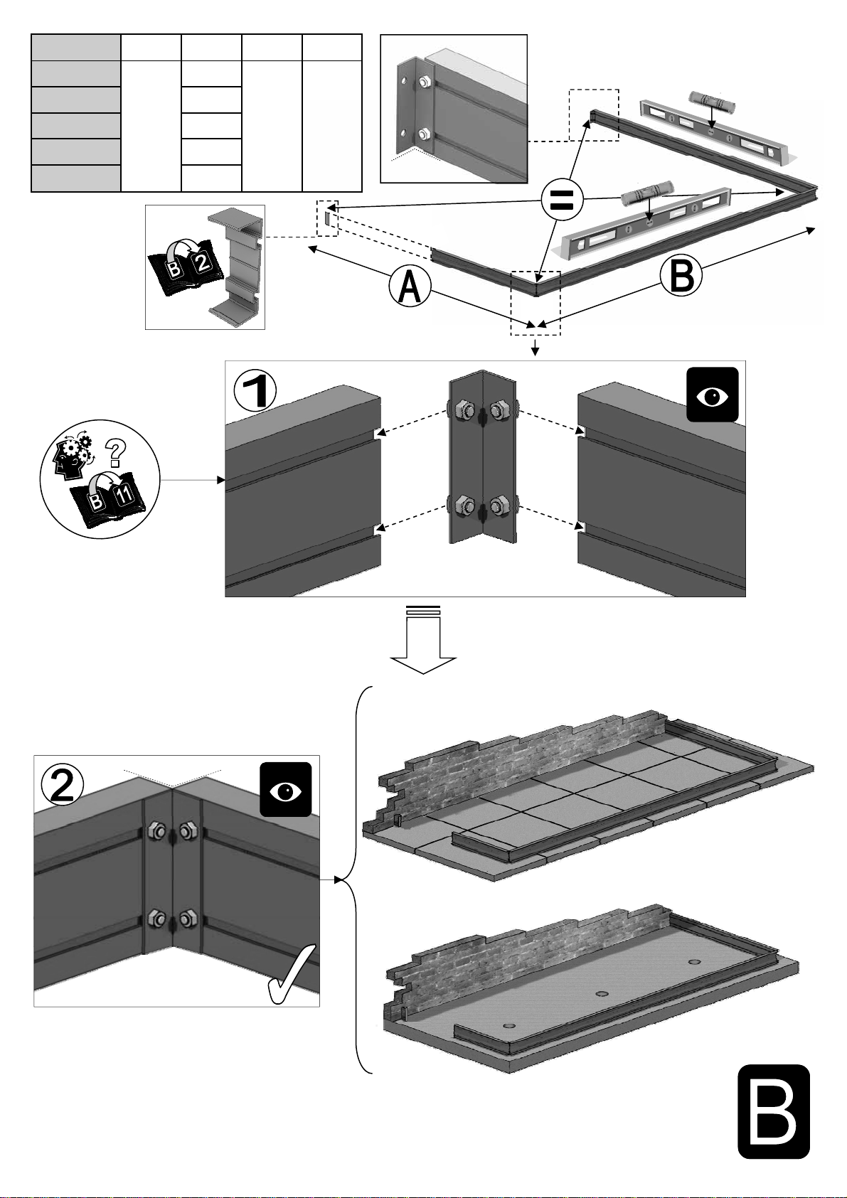
These instructions are divided into sections; B-base, partlists,1-side (please see SIDE DOOR OPTION if you have chosen an optional ’side door’ and be
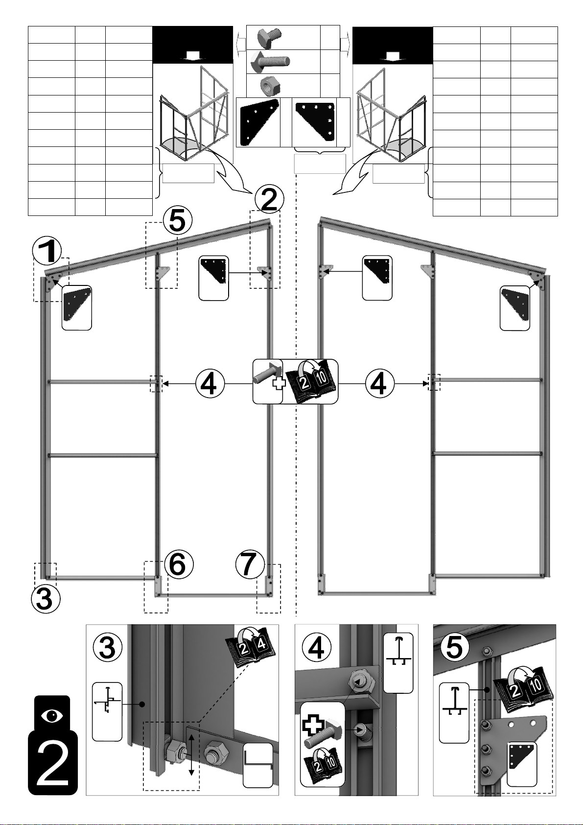
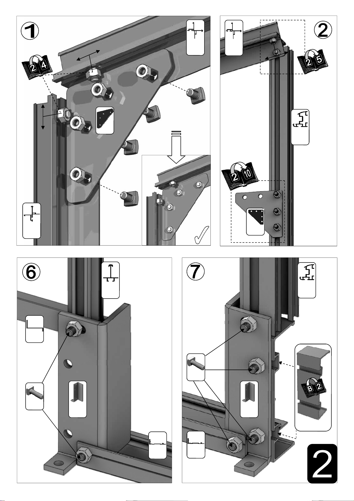
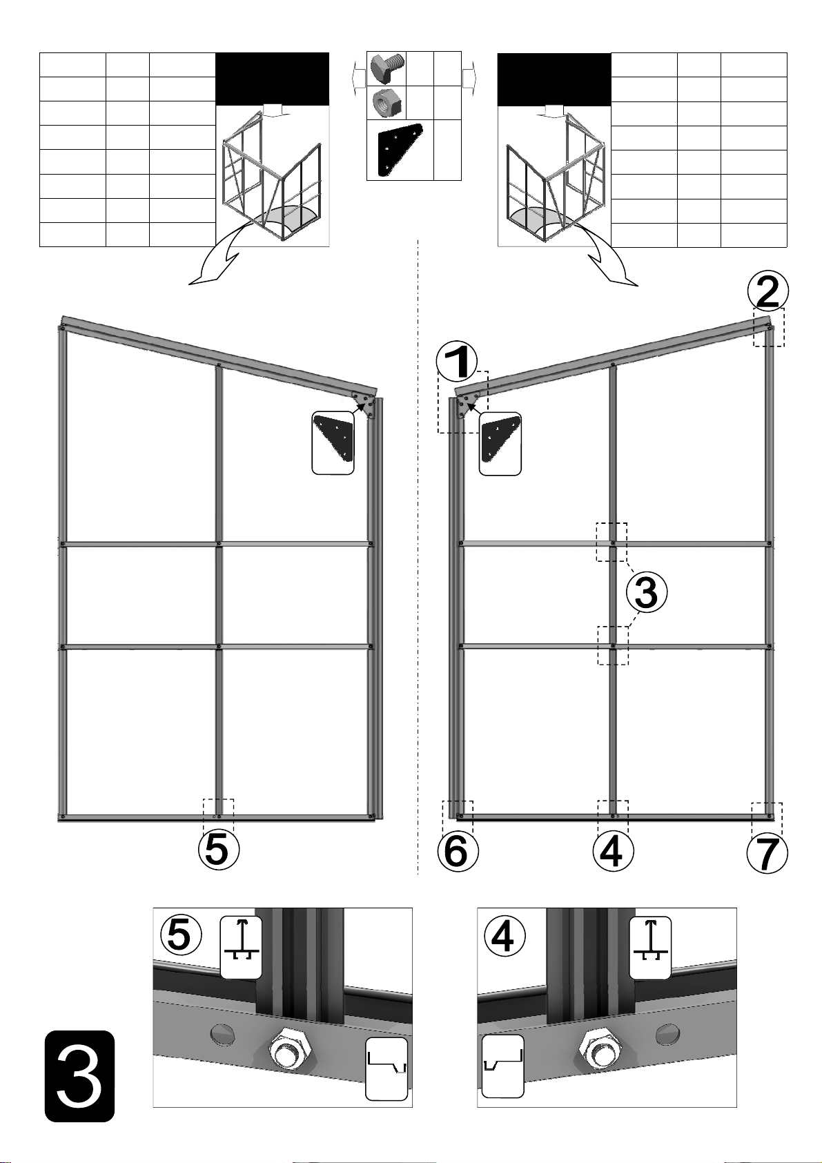
aware that its inclusion will result in part amendments), 2-left gable, 3-right gable, 4-joining the three sides, 5-roof, 6-vent, 7a / 7b -door/s, 8-glazing
(8a toughened glass, 8b horticultural glass), 9-vent attachment, 10-door attachment, 11 anchoring down, SIDE DOOR OPTION, back cover-packing list. If
you need to contact us for assistance please refer to the relevant section/s.
Safety Warning
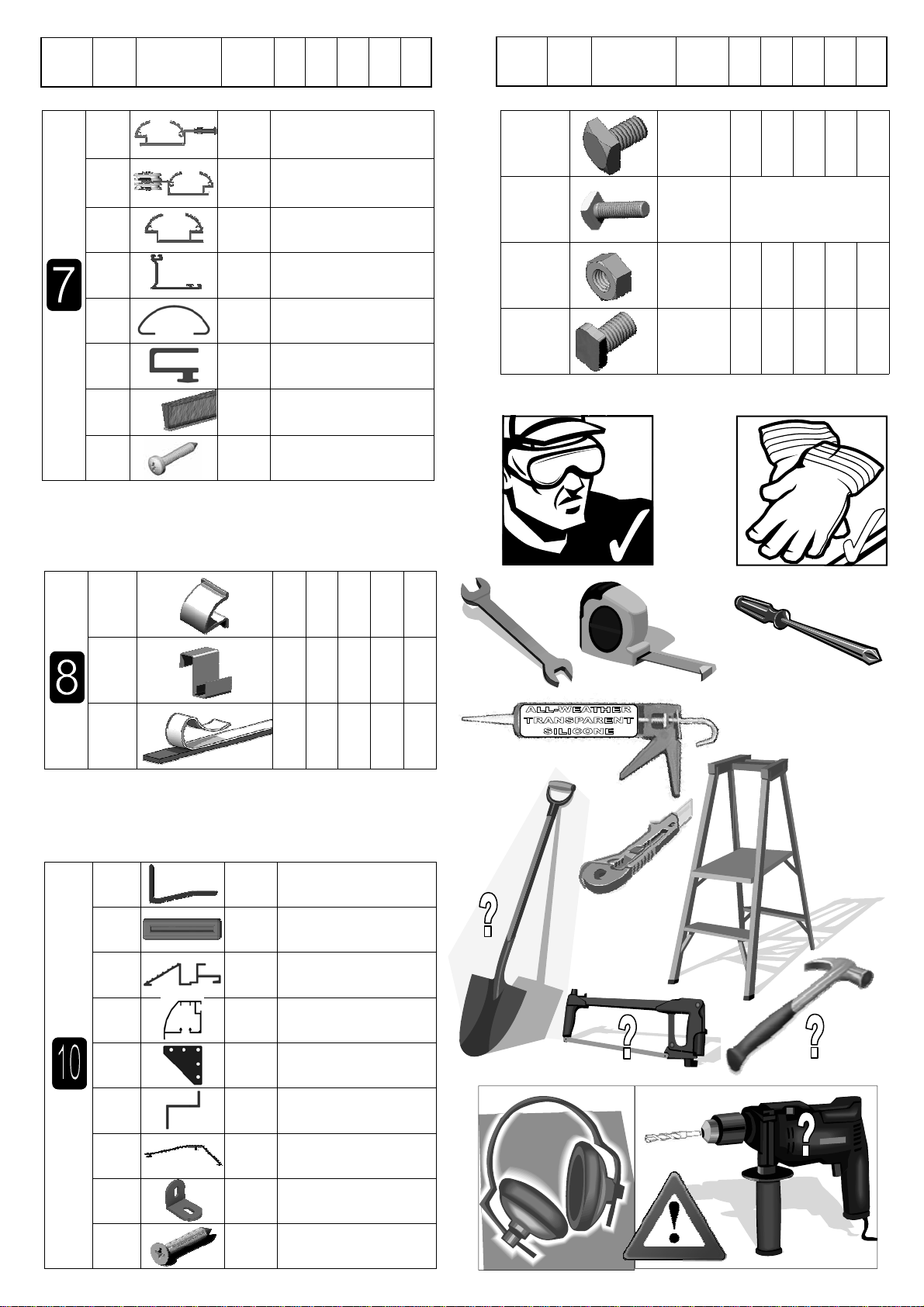
Glass and aluminium can potentially cause injury. Please ensure you wear protective goggles, gloves, headgear and suitable footwear when
assembling and glazing the building.
Please remember that glass is fragile and should be handled with extreme care. Always clear up and dispose of any breakages immediately.
Do not assemble the greenhouse in high winds.
For safety reasons and ease of assembly, we recommend that this greenhouse is assembled by a minimum of two people.
Please clear all lying snow from the greenhouse roof as it can cause the roof to buckle or collapse.
Site Preparation
When selecting a site for your greenhouse, it is vital that you choose as flat and level an area as possible.
A concrete or slabbed base will provide the most solid foundation for your greenhouse.
IMPORTANT: Do not fix your building down until the building is fully assembled, including glazing.
Avoid placing your greenhouse under trees or in other vulnerable locations.
To minimise the risk of wind damage, try to select as sheltered a site as possible, e.g. beside a hedgerow or garden fence.
Additional Considerations
Please bear in mind that assembling your greenhouse can be time consuming. You may need to spread the construction over two or more
days. We recommend that you avoid leaving the building partially glazed. If you ever have to leave your greenhouse half assembled and not
anchored down, weigh it down with slabs or bags of sand to stop the wind moving it.
You will find it helpful to prepare a large, clean and clear area in which to work in. A garage floor or flat lawn area is ideal.
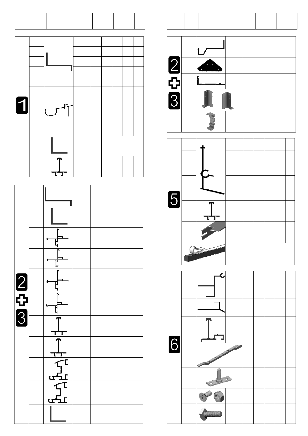
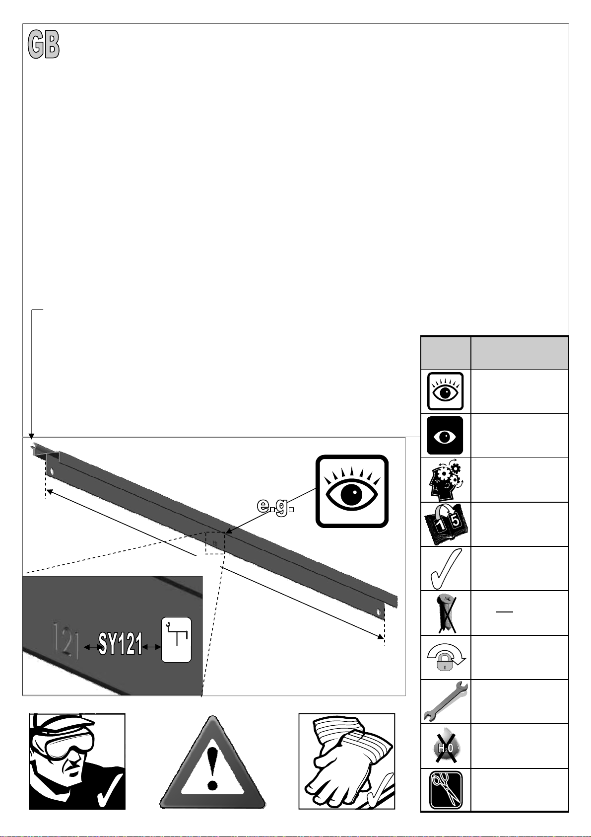
If you have arranged for someone to install your greenhouse for you, please check that all components are included. Most parts are numbered
and can be identified by a stamped number (without the ’SY’, ‘HE’, ‘CL’) or removable label. Alterna-
tively, the components can be identified by lengths detailed in the packing list (see diagram below).
Please also note that NOT all parts for a specific area will be packed together, i.e. door related com-
ponents are packed together and some are used in main frame construction.
Anchoring down your greenhouse should be the final stage of construction (including glazing).
Once installed your greenhouse requires little maintenance, but to maintain the smooth running of
your door(s) WD40 or similar can be applied to the door wheels and lower door guides.
Guarantee
Your new Castle greenhouse is guaranteed for 10 years against faulty manufacture of the frame-
work. This does not include glazing, moving parts, accidental damage or wind damage.
610mm
121
KEY
SYMBOL KEY DESCRIPTION
EXTERNAL VIEW
THINK
THIS SECTION
RELATES TO
ANOTHER
(e.g. 1 to 5)
CORRECT
DO NOT FIX DOWN!
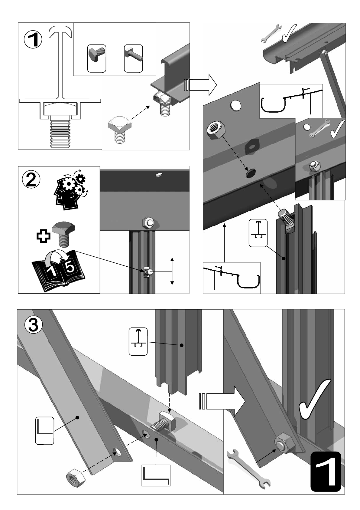
TWIST TO LOCK
TIGHTEN
DO NOT WET!
CUT TO LENGTH
INTERNAL VIEW