18
Routine maintenance entrusted to specially instructed
surgery staff (draw. 3 page 43)
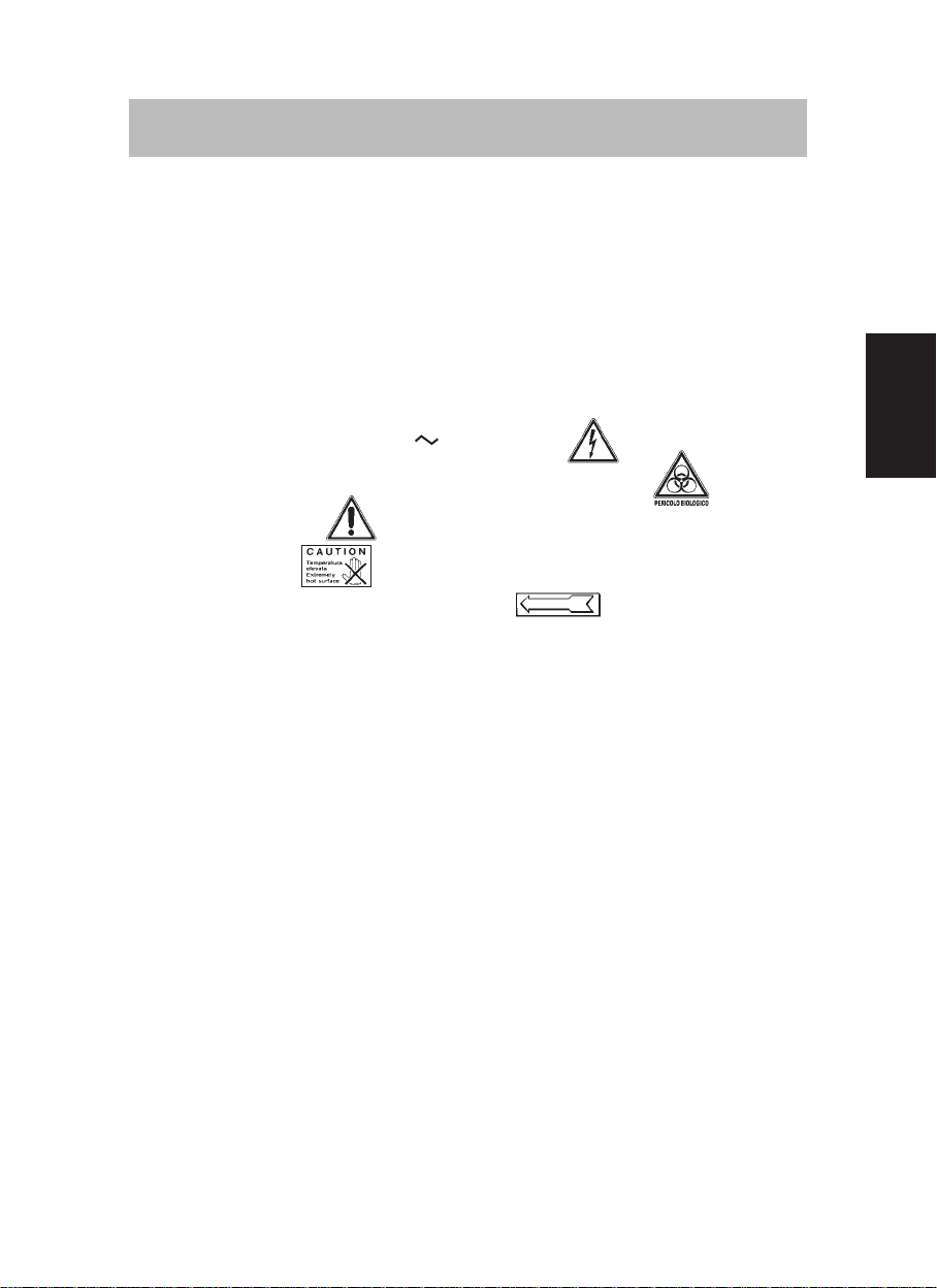
• Electrical shock risk : also 230V can be lethal.
• General danger sign.
• Biological danger, risk of infections from epidemic diseases.
• Compulsory direction of flow or of rotation.
1)
After each surgical operation or particularly long operations, aspirate abundant clean
water to rinse the suction piping.
2)
At the end of each working day, clean and disinfect the appliance using a specific
productfordentalaspiratorsand amalgamseparators.Wesuggest,forexample,Puli-Jet
plus (for dilution with water, refer to our directions). Do not use aggressive or foaming
products.
3)
The dirty filter(17) mustbereplaced every day.Handleitwithcare toprevent contamina-
tion and the return of solid trapped particles into the filter.Any material trapped in the
filter must be collected and disposed of according to the regulations in force.
4)
Werecommend placingonedisinfectant antifoam tabletin thedental unitsecretion filter
every morning before starting the aspiration.
5)
In case the appliance is treated with products which are different from the ones recom-
mended by the importer, the correct working of the equipment might be compromised
and faults could occur.
6)
Check that there are no liquid leaks. In case of working anomalies or alarms, contact
the technician.
Faults report and possibile solutions
The amalgam container filling levels are the only alarms directly linked to the Hydro-
cyclone.
Below is information useful to inform the reader about possible problems that may
cause the aspiration to stop and that may compromise the working of the “Separatore
Centrifugo Compatto” for the Hydrocyclone.
With the circuit board AC58 (draw. 6 page 46)
1)
If led number 32 is off it means that there is no power supply: check that the machine
switch and the master switch are on, in case they are on but light 32 is still off, contact
the technician.
2)
The sound of the alarm and the alternation of the flashing of the yellow led 18 (double
flashing)and theone ofthe redled20(onesingle flash)indicate thatthe AC58 ampero-
metric control system has detected an anomaly in the centrifugal separator current
absorption. Such an anomaly could have different causes: mechanical blockage or
a drain obstruction (8) (draw. 3 page 43) of the Hydrocyclone or a temporary voltage
decrease.
Disconnect the appliance from the mains for a few seconds to reset the alarms and to
start the appliance again. In case the alarm appears again, contact the technician.
With the circuit board AC80 (draw. 6 page 46)
1)
If the display (22) is off it means that there is no power supply:check that the machine
switch and the master switch are on, in case they are on but the machine is still off,