Cavitar CAVILUX Smart User manual

CAVILUX®Smart
Operating Manual

Contents
1INTRODUCTION.........................................................................................................................1
2SAFETY INFORMATION..........................................................................................................2
3PROPERTIES...............................................................................................................................5
4INSTALLATION........................................................................................................................11
4.1 SOFTWARE INSTALLATION ...................................................................................................11
4.2 HARDWARE INSTALLATION..................................................................................................13
5OPERATION ..............................................................................................................................16
5.1 PRELIMINARY ISSUES ...........................................................................................................16
5.2 CAVILUX CONTROL SOFTWARE.........................................................................................16
5.2.1 General...........................................................................................................................17
5.2.2 Choosing the operation mode.........................................................................................18
5.2.3 Programming pulse patterns ..........................................................................................19
5.2.4 Trigger settings...............................................................................................................20
5.2.5 Power settings.................................................................................................................21
5.2.6 Activating the outputs.....................................................................................................21
5.2.7 Example: using CAVILUX Control software..................................................................23
5.3 AFTER OPERATION ...............................................................................................................23
5.4 USEFUL INFORMATION .........................................................................................................24
5.4.1 Spot sizes at different working distances........................................................................24
5.4.2 Maximum repetition rates for different pulse durations.................................................25
5.4.3 Calculation of pulse energy............................................................................................25
5.4.4 Dependence of wavelength on temperature....................................................................25
5.4.5 Ultra high speed operation.............................................................................................26
5.4.6 Typical steps in using a complete visualization system ..................................................26
5.4.7 Troubleshooting..............................................................................................................28
6MAINTENANCE AND SERVICE INFORMATION.............................................................30
7SUPPORT, ACCESSORIES AND END OF LIFE..................................................................31
8LIMITED WARRANTY............................................................................................................32
CAVILUX Smart, Operating Manual, Version 4.4
© 2011 Cavitar Ltd.
All rights reserved. All unauthorized copying strictly prohibited.
CAVILUX®is a registered trademark of Cavitar Ltd.
ii

1
1 Introduction
Thank you for choosing CAVILUX Smart!
CAVILUX®Smart is a Finnish quality product developed and manufactured by Cavitar Ltd.
We hope that you will be satisfied with your product.
CAVILUX Smart is a versatile, accurate, reliable and easy-to-use pulsed high power diode
laser light source designed especially for the visualization of challenging processes in
scientific and industrial R&D. CAVILUX Smart enables the continuous real-time
measurement of several different process parameters such as morphology, homogeneity,
track, velocity and acceleration.
CAVILUX Smart suits especially well for the visualization of small, fast and/or hot objects.
Since CAVILUX Smart provides high temporal accuracy and speed, the camera can be
chosen rather freely according to the requirements of the process. For example, it is possible
to use a low frame rate and high resolution camera for continuous online process monitoring
and control.
Please read this operating manual carefully before using CAVILUX Smart.
Chapter 2 contains important safety information for the safe operation of CAVILUX Smart.
Chapter 3 describes the properties of CAVILUX Smart and Chapter 4 deals with the
installation of the system.
Chapter 5 describes the operation of CAVILUX Smart. Please note that there is plenty of
useful information related to the use of CAVILUX Smart in Section 5.4. As an example,
troubleshooting is covered in Section 5.4.7.
Chapters 6 to 8 cover issues related to maintenance, service, support, accessories and
warranty.
The symbols below will be utilized throughout this operating manual:
NOTE! indicates useful tips for easier operation
CAUTION! indicates potential risk of serious damage to the device
WARNING! indicates potential risk of serious injury to the user

2
2 Safety information
PLEASE CAREFULLY READ AND UNDERSTAND THE FOLLOWING SAFETY
INSTRUCTIONS BEFORE USING CAVILUX SMART. IT IS OF UTMOST
IMPORTANCE TO STRICTLY OBEY THESE INSTRUCTIONS. OTHERWISE SERIOUS
DAMAGE TO THE USER OR TO THE DEVICE MAY OCCUR.
ONLY A PERSON, WHO HAS CAREFULLY READ AND UNDERSTOOD ALL SAFETY
INSTRUCTIONS BELOW AND THE REST OF THIS OPERATING MANUAL, IS
QUALIFIED FOR USING CAVILUX SMART. CAVITAR LTD. IS NOT LIABLE FOR
ANY DAMAGE CAUSED BY THE IMPROPER USE OF CAVILUX SMART.
CAUTION--USE OF CONTROLS OR ADJUSTMENTS OR PERFORMANCE OF
PROCEDURES OTHER THAN THOSE SPECIFIED HEREIN MAY RESULT IN
HAZARDOUS RADIATION EXPOSURE.
CAUTION--USE OF OPTICAL INSTRUMENTS WITH THIS PRODUCT WILL
INCREASE EYE HAZARD.
WARNING!
CAUTION!
•CAVILUX Smart is a class 4 laser product.
olaser class is indicated by the yellow warning label on top of the laser unit
possible warning labels are shown above. Warning text depends on
whether the output wavelength is 690 nm (the warning label on the left)
or 810 nm (the warning label on the right)
olaser apertures on the laser unit and on illumination optics are indicated by
yellow aperture labels (see the label above)
•Do not look into the direct, reflected or scattered laser beam!
o690 nm laser unit emits visible red laser light at 690 ± 10 nm wavelength band
o810 nm laser unit emits invisible laser light at 810 ± 10 nm wavelength band
owear suitable laser safety goggles (always ensure that the goggles protect
especially for the emission wavelength band of the laser!)
•The accidental exposure to direct/reflected/scattered laser beam has to be prevented:
outilize suitable casings, curtains, beam blockers/absorbers, closed doors,
Remote Interlock (RIL) feature and warning plates/lights/sounds in such a way
that no one can enter the region of potential laser exposure by accident
opay special attention to possible bystanders or persons passing by
oensure that the key is removed from the control unit after use

3
•Before turning the device on, make sure that (in addition to the instructions above):
oeveryone inside the region of potential laser exposure wears laser safety
goggles that block laser radiation at 690 ± 10 nm and/or at 810 ± 10 nm
othe laser output and laser light blockers/absorbers are aligned and positioned in
such a way that the direct/reflected/scattered laser beam will not be dangerous
to anyone
•If the laser is to be used at high duty cycle and if the beam is to be focused tightly, the
possible risk of fire or explosion in the presence of flammable materials has to be
taken into account
•Ensure that there is no risk of unintentional voltage signal/peak (e.g. static discharge)
at the Set Mode I/O (SMIO) connector, since this may enable/disable laser output (see
Chapter 3 for more information)
•Other instructions:
oDo not make ANY modifications to the device by yourself
CAVILUX Smart is not certified for medical use
oDo not try to repair the device by yourselfo
oIt is strictly forbidden to open the cover of the laser unit or the control unit.
Otherwise serious damage or injury to the user or to the device may occur.
Laser unit contains gallium arsenide, which is a known human carcinogen
oDo not expose the system to moisture, rain or condensing environment
Before turning the device on, ensure that all connections are properly made
oExcessive vibration or strong mechanical impact may damage the equipmento
oThe operating temperature of CAVILUX Smart is +10…+40 °C. Do not
expose CAVILUX Smart to excessively low or high temperatures
oIf you are uncertain about any issue related to safety or proper operating
conditions, please contact your vendor or Cavitar
CERTIFICATIONS:
•Cavitar Ltd. is an ISO 9001:2008 certified company
•EC- cde laration of conformity
othe device fulfils the requirements of the following directives/standards:
Low Voltage Directive (LVD) 2006/95/EC
Directive of Electromagnetic Compatibility (EMC) 2004/108/EC
Laser Safety Standard EN/IEC 60825-1
•Cer ctifi ations for USA and Canada
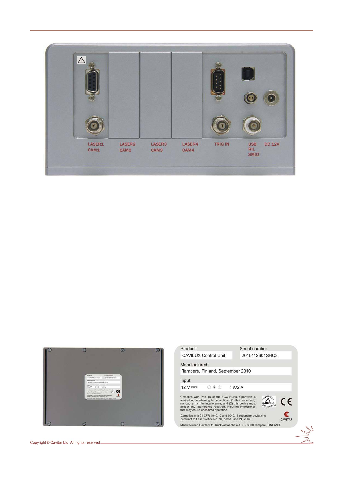
oComplies with 21 CFR 1040.10 and 1040.11 except for deviations pursuant to
Laser Notice No. 50, dated June 24, 2007.
oThis device complies with Part 15 of the FCC rules. Operation is subject to the
following two conditions: (1) this device may not cause harmful interference,
and (2) this device must accept any interference received, including
interference that may cause undesired operation.

4
SAFETY FEATURES OF CAVILUX Smart:
•Safo
ualified for using CAVILUX Smart
•Key
e device is not in use.
unauthorized use of CAVILUX Smart
•Rem te
someone enters the region of potential laser exposure
•Me .
•Las e
•Las w tes the laser
operation time of 10 s in High Speed Mode
•Las s
othe laser safety goggles delivered together with CAVILUX Smart provide
good protection at the laser wavelength band (690 ± 10 nm or 810 ± 10 nm)
ety information in this manual
this safety information as well as the whole Operating Manual need to be fully
read and understood before a person is q
-operated master control for power on/off
oonly a person qualified for using CAVILUX Smart has the right to possess the
key for the key-operated master control for power on/off
the key has to be removed from the control unit when thoThis prevents the
o Interlock (RIL)
when used correctly, this safety feature ensures that the laser output will beoswitched off in case
chanical beam stopper
a mechanical beam stopper is permanently attached to the illumination opticsoMount the beam stopper to the illumination optics for stopping the beam
er mission indicating devices
o“POWER” led on the control unit front panel and the green light on the laser
unit power supply indicate that the generation of laser light is possible
oUSA and Canada only: green power indicator led in the laser unit back panel
indicates that the generation of laser light is possible
“PULSE” led on the control unit front poanel is on when laser light is generated
er arning label and laser aperture labels
olaser warning label states applicable warning texts as well as indica
class and the related safety standards
olaser aperture label indicates the location of the laser output beam
•Maximum continuous
othe laser output will automatically stop after 10 s in High Speed Mode
er afety goggles

5
3 Properties
CAVILUX Smart typically consists of the following components:
LASER UNIT
•class 4 laser product (see the yellow warning label on the laser unit)
•laser aperture label
•pulse power 200…500 W ± 10 % (see the device label on the bottom of the laser unit)
•pulse rise time <20 ns
•wavelength 690 ± 10 nm or 810 ± 10 nm (see the device label on the bottom of the
laser unit)
•four mounting holes on the bottom (M4 thread)
•physical dimensions approximately 36 mm x 62 mm x 150 mm (laser connector
requires additional space behind the laser unit)
CONTROL UNIT
•2…8 independently programmable outputs for laser units and cameras
•bursts of pulses with up to five pulses and five delays can be programmed to each
output
•resolution 10 ns (all outputs) n ~20 ns …10 μs•each laser pulse duration independently programmable betwee
•max. laser output duty cycle (DC) 0,1 % (High Speed Mode)
•TRIG IN connectors for external synchronization
•USB connector for programming the control unit with a computer
commands using logic input
r control for power on/off
•digital laser power adjustment (with CAVILUX Control software)
CA
•for controlling CAVILUX products, see Chapter 5
ADJUSTABLE ILLUMINATION OPTICS
ination
CA
unit
TORAGE CASE, LASER SAFETY GOGGLES AND TOOLS
•Remote Interlock (RIL) connector
•Set Mode I/O (SMIO) connector for start/stop
•key-operated maste
•Start/Stop button
VILUX CONTROL SOFTWARE
•fiber optic light guide, length 2 m
•focusing optics for uniform illum
BLES & POWER SUPPLIES
•USB cable between computer and control unit
•laser cable between laser unit and control
•power supply (DC 12 V) for control unit
INSTALLATION CD INCLUDING OPERATING MANUAL
S

6
Table 3.1. CAVILUX Smart specifications.
Optical
Wavelength 690 ± 10 nm or 810 ± 10 nm
Pulse output power (± 10 %)200 W, 400 W or 500 W
Pulse duration ~20 ns – 10 μs
Pulse energy ~4…10 μJ – 2…5 mJ
Max duty cycle (DC) 0,1 % (for a duration of max 10 s)
Max average power 0,2…0,5 W ± 10 % (for a duration of max 10 s)
Laser class (according to EN/IEC 60825-1:2007) 4
Standard fiber core diameter 3 mm (5 mm for 400 W laser @ 690 nm)
Standard fiber numerical aperture 0,4~
Standard fiber minimum bend radius 5 cm1
Electrical
Control unit power supply input voltage AC 100-240 V, 47-63 Hz
Control unit power supply output voltage C 12 VD
Control unit power supply power rating 25 VA
Mechanical
Control unit dimensions )~100 mm x 123 mm x 190 mm (excl. connectors
Control unit weight ~1,9 kg (depends on configuration)
Laser unit dimensions ~ 36 mm x 62 mm x 150 mm (excl. connectors)
Laser unit weight ~0,5 kg
Laser unit attachment 4 x M4 mounting holes, depth 4 mm
CAVILUX Smart storage case dimensions 206 mm x 428 mm x 524 mm~
CAVILUX Smart system weight (incl. case) ds on configuration)~9 kg (depen
Environmental
Storage temperature 0…+50 °C
Operation temperature +10…+40 °C
Humidity max 80 % RH non-condensing
Shock resistance max 25 G
Supply voltage fluctuations ±10 %
Overvoltage category II
Table 3.2. Description of symbols.
Danger: Refer to this manual (ISO 7000-0434)
Direct current (IEC 60417-5031)
Alternate current (IEC 60417-5032)

7
Fig. 3.1. Front panel of CAVILUX Control unit.
Front panel controls:
OFF/ON key-operated master control for power on/off
START/STOP manual button for activating/disabling the outputs
Front panel indicators:
POWER green led indicates that the device is ON
ACTIVE yellow/orange led indicates that the device is initializing (blinking),
cooling (blinking) or activated (on), i.e. generating pulses or waiting
for external trigger
PULSE red led indicates that the device is generating pulses
RIL red led indicates that the terminals of the RIL connector are
open-circuited (EN/IEC 60825-1)
Fig. 3.2. Examples of front panel indicator operation.

8
Fig. 3.3. Rear panel of CAVILUX Control unit.
Rear panel connectors:
LASER1…4 D9 connector for connection between control unit and laser unit
CAM1…4 BNC connector for connection between control unit and camera
TRIG IN BNC connector for external synchronization (TTL, allowed voltage
range +0…5 V, input impedance approximately 34 kΩ)
D9 connector for external synchronization (only to be used together
with Cavitar optical triggers)
USB USB connector for programming the control unit with a computer
RIL Connector for remote interlock operation. The device will not emit
laser radiation when the terminals of the RIL connector are open-
circuited (EN/IEC 60825-1). Mating plug is LEMO
FGG.0B.302.CLAD52Z
SMIO Set Mode I/O for activating and disabling the outputs (optocoupler
input; 0...+1 V Ælogic 0; +4…+24 V Ælogic 1). In harsh
environment it is recommended to protect the unused input against
unintentional switching with e.g. suitable termination resistance
DC 12V 5,5 / 2,1 mm dc connector for DC 12 V power supply.
(Polarity: Positive pole in the center)
Fig. 3.4. Bottom view of CAVILUX Control unit (device label magnified on the right).

9
Front
Fig. 3.5. CAVILUX Smart laser unit (device label magnified on top).
Fig. 3.6. Adjustable illumination optics (laser aperture and warning labels shown).

10
Fig. 3.7. Bottom view of control unit power supply.
CAUTION!
•Do not connect other than the supplied control unit power supply to the control unit.
•Only connect the control unit power supply to a wall socket with protective
grounding.
•If needed, control unit power supply can be disconnected from the mains supply by
removing the control unit power supply plug from the wall socket.

11
4 Installation
4.1 Software installation
If applicable, please uninstall old software version before installing new software version!
Insert the CAVILUX Software CD into the CD drive and run the setup file. Follow the
instructions on the screen. The screenshots below are valid for Windows XP. In case
Windows logo test message box appears, please click "Continue Anyway" (see Fig. 4.1).
After this software installation will be completed.
Fig. 4.1. Windows Logo test message box, click "Continue Anyway".
When the control unit is turned on and connected to the computer for the first time (or when
connected to a new USB port for the first time), Windows starts to install CAVILUX drivers.
Follow the driver installation instructions below (Figs. 4.2 – 4.4).
Fig. 4.2. Do not connect to Windows Update, choose “No, not this time” and click "Next".

12
Fig. 4.3. Choose "Install the software automatically" and click "Next".
Fig. 4.4. Windows Logo test message box, click "Continue Anyway".
The installation of CAVILUX Control software and CAVILUX drivers is completed.
.
NOTE!
•The software has to be installed before connecting the control unit to computer.
•The software is designed for Windows XP/Vista/7 environment.
•The software requires Microsoft .NET Framework 2.0 and Microsoft Visual C++
2008 Redistributable Package which are included in CAVILUX Control installer
(starting from version 4.3).

13
4.2 Hardware installation
Installation of laser unit
The laser unit should be placed on a firm and stable surface so that the object can be properly
illuminated with illumination optics. Also the safety instructions in Chapter 2 need to be taken
into account. In the illumination of objects that may cause excessive radiation, heat, vibration
or mechanical forces (e.g. explosions and materials processing) the laser unit (and
illumination optics) need to be properly protected. If you feel uncertain about the correctness
of the installation and/or about the suitability of the environment, please contact your vendor
or Cavitar. Warranty does not cover damage caused by improper installation.
Installation of illumination optics to the laser unit
Illumination optics contains a fiber optic light guide. This provides versatility for different
illumination requirements. A focusing lens is installed to the end of the light guide for the
generation of uniform illumination. Cavitar can also provide other illumination solutions such
as back illumination or line illumination (see Chapter 6).
The installation of the fiber optic light guide includes the following steps:
•loosen the fiber optic light guide locking screw (on the laser unit fiber connector)
•install/change the fiber optic light guide
•gently tighten the locking screw
The focusing lens is installed as follows:
•thread the end of the fiber optic light guide inside the housing of the focusing lens
•gently tighten the locking screw(s) in the lens housing, do not use excessive force!
NOTE!
•In most cases the laser unit can be installed in a safe place by using a sufficiently
long fiber optic light guide.
•The optical surfaces of illumination optics and fiber optic light guide need to be kept
clean. Dirty optical surfaces reduce the amount of light reaching the object.
•The focusing lens produces a uniform illumination on a certain distance. This
distance and the size of the illuminated area depend on the distance between the
fiber optic light guide and the lens. A suitable illumination can be found by sliding
the end of the fiber optic light guide back and forth with respect to the housing of
the focusing lens. More information about this can be found from Section 5.4.1.
•Make sure that the laser unit end of the fiber optic light guide is pushed to the
bottom of the connector on the laser unit. Otherwise a significant amount of light
may not be coupled to the fiber optic light guide.

14
CAUTION!
•Do not use force while pushing the end of the fiber optic light guide to the connector
in the laser unit. Handle the fiber optic light guide with special care.
•The fiber optic light guide will not tolerate excessive mechanical forces. Do not
bend the light guide excessively and do not exceed the specified operation
temperature of CAVILUX Smart.
Installation of control unit
Control unit shall be placed on a firm surface. The safety instructions in Chapter 2 need to be
taken into account.
Making the connections
The connections shall be made in the following order:
•check that the status of the control unit key-operated master control is ”OFF”
•connect your RIL circuit to the RIL connector (LEMO EPG.0B.302.HLN socket)
•connect the D9 connector of the laser cable to the LASER connector of the control
unit and the M16 connector of the laser cable to the laser unit
•connect the control unit power supply (DC 12 V) between AC outlet and control unit
•in case that the control unit is used to control camera(s), connect a BNC cable between
CAM connector of the control unit and camera
•in case that external synchronization is utilized, connect the external signal source to
the TRIG IN connector of the control unit. Two TRIG IN connectors are available:
o
oother trigger signals shall be connected to the BNC connector, allowed signal:
TTL, 0…+5 V (input impedance approx. 34 kΩ). For low impedance signal
sources a termination resistance of corresponding value must used at input
connector
an optical trigger provided by Cavitar shall be connected to the D9 connector
•in case that an external logic signal is used for activating and disabling the outputs,
connect the external logic signal source to the SMIO connector of the control unit
(BNC connector)
•in case that the control unit is to be programmed or operated with a computer, connect
the USB2 cable between the computer and the control unit. Make the connection only
after the computer has fully started!

15
NOTE!
•To enable laser operation, the terminals of the Remote Interlock (RIL) connector
(LEMO EPG.0B.302.HLN socket) need to be short-circuited together (do not
connect to ground!). To disable operation, disconnect the terminals from each other.
The device will not emit laser radiation when the terminals of the RIL connector are
open-circuited (IEC/EN 60825-1).
CAUTION!
•Only a TTL signal within the voltage range 0…+5 V can be delivered to the
TRIG IN BNC connector. E.g. negative voltage and/or excessively large voltage
may damage the control unit.
WARNING!
•Ensure that there is no risk of unintentional voltage signal/peak (e.g. static discharge) at
the Set Mode I/O (SMIO) connector, since this may enable/disable laser output (see e.g.
Chapter 3 for more information).
•Ensure that the locations of all operation and adjustment controls as well as other
system components are such that neither the operator nor anybody else can be exposed
to laser radiation. Pay special attention to the placement of control unit and computer as
these usually need to be accessed regularly during operation.
•Ensure that all system components are placed in such a way that the applicable mains
plugs are always easily removable from the electrical network.

16
5 Operation
After successful installation CAVILUX Smart is ready for operation. In the following the
operation of the system is described in more detail.
5.1 Preliminary issues
Before operation the following preliminary issues need to be performed:
•check that laser unit, illumination optics and control unit are installed appropriately
and that all optical surfaces are clean
•make sure that the key-operated master control of the control unit is ”OFF”
•make sure that the connections are as described in Section 4.2
•make sure that the safety instructions (Chapter 2) have been properly followed
•turn the control unit key-operated master control to ”ON”
oNote1: if the USB cable is connected to a computer for the first time, driver
installation will start, see Section 4.1
•wait until the control unit has initialized (during initialization the “ACTIVE” led is
blinking, see Chapter 3), this will take approximately 10 seconds
•if the control unit is to be programmed or controlled with a computer, start CAVILUX
Control software (this requires that the USB2 cable is connected between the
computer and the control unit)
N
OTE!
•After turning the key-operated master control to “ON”, the control unit will perform
initialization routines. This can last max 10 s. During this time a yellow led indicator
(ACTIVE) will blink in the front panel of the control unit and the control unit will
not respond to commands from CAVILUX Control software.
5.2 CAVILUX Control software
The control unit can be programmed and controlled with CAVILUX Control software. The
program is designed to be as versatile and easy-to-use as possible. The program also includes
ophisticated safety check routines to protect the laser unit.s
In the following the operation of the program is discussed in detail. Section 5.2.1 deals with
general features, Section 5.2.2 with the selection of the operation mode and Section 5.2.3 with
the programming of pulse patterns. Section 5.2.4 concentrates on triggering properties and
Section 5.2.5 on power settings. Section 5.2.6 describes how to activate the outputs and
ection 5.2.7 presents an example on how to use the program.S

17
5.2.1 General
The front panel of the CAVILUX Control program is presented in Figs. 5.1 (Normal Mode)
nd 5.2 (High Speed Mode). The software version in the figures contains eight output
hannels, but the number of output channels can be e.g. two.
a
c
Fig. 5.1. The front panel of CAVILUX Control software (Normal Mode).
Fig. 5.2. The front panel of CAVILUX Control software (High Speed Mode).

18
CAVILUX Control contains three menus (File, Setup and Help) with the following functions:
File:
New Open a new file for pulse pattern generation.
Open Open a previously saved file for pulse pattern generation.
Save Save the current pulse pattern settings with the existing file name.
ave As Save the current pulse pattern settings with a new file name.
Exit the program.
Setup:
S
Exit
Settings is started.
r log file location: define a log file for saving information about the
how Messages
User can select whether info messages are shown on the screen or not.
Help:
Default pattern file location: define a previously saved pulse pattern generation
file that will be loaded when the program
Use
operation of the program.
S
al t.
Launch the CAVILUX HF Operating manual in pdf-format.
About Information about the program.
AVILUX Control can be used in Normal Mode (“Normal”) or in High Speed Mode
max. duty cycle of 0,3 ‰. Duty cycle is the
action of time that the laser is generating light. As an example, the generation of 1 μs pulses
f 1 ‰ for max. 10 s. After this the system will start a cooling period, during which the
is procedure is also valid for external triggering
ith internal settings. With other external triggering options the system will run for 10 s after
It is possible to operate CAVILUX Smart at very high duty cycle (up to 90 %) for very short
time (max. total laser active time 10 μs). Please see Section 5.4.5 for more details.
CAVILUX Smart Manu
Launch the CAVILUX Smart Operating manual in pdf-forma
CAVILUX HF Manual
5.2.2 Choosing the operation mode
C
(“High”). The operation mode can be selected in the “Speed” block.
Normal mode is convenient e.g. while adjusting and aligning the visualization system. In this
mode the system can operate continuously at a
fr
at 300 Hz corresponds to a duty cycle of 0,3 ‰.
High Speed Mode is convenient when higher repetition rates are required. Such needs may
appear e.g. with high speed cameras. In this mode the system can operate at a max. duty cycle
o
system will be inactive. After the cooling period the system will remain inactive.
The duration of the cooling period depends on the total laser active time during pulsing. With
internal triggering (see Section 5.2.4) the cooling period is determined in such a way that the
total laser active time divided by the cooling period results in a duty cycle of 0,17 ‰. For
example, if the system operates at 1 ‰ duty cycle for 10 s (total laser active time 10 ms), the
cooling period will be approximately 60 s. Th
w
which a 60 s cooling period will take place.
This manual suits for next models
1
Table of contents
Popular Measuring Instrument manuals by other brands

OKM
OKM BODY SCREENER user manual

Viavi
Viavi G3-GSP-2P100-8TSSD Hardware installation

iSystem
iSystem iC5000 Hardware reference

Hoymiles
Hoymiles HMS-1600-4T Quick installation guide

Veeder-Root
Veeder-Root EMR3 XStream-PKG Spring Installation Instructions

Camlogic
Camlogic PFG05 Series Use and maintenance manual