Cavitar C300 User manual

CAVITAR
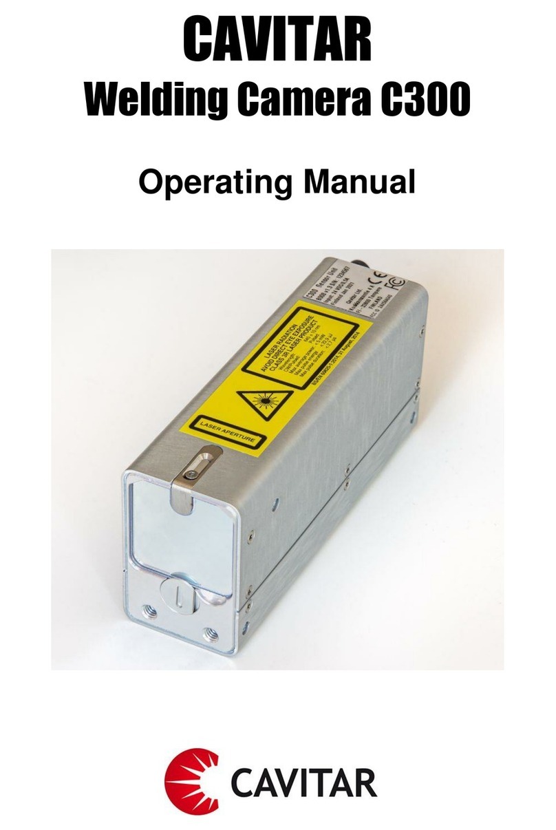
Welding Camera C300
Operating Manual

ii
Contents
1INTRODUCTION.........................................................................................................................1
2SAFETY INFORMATION..........................................................................................................2
3PROPERTIES...............................................................................................................................5
4INSTALLATION........................................................................................................................11
4.1 SOFTWARE INSTALLATION ........................................................................................................11
4.2 HARDWARE INSTALLATION.......................................................................................................15
5OPERATION ..............................................................................................................................18
5.1 BEFORE OPERATION ..................................................................................................................18
5.2 CAVITAR CAPTURE SOFTWARE ..............................................................................................18
5.2.1 Registration ....................................................................................................................19
5.2.2 Opening the camera........................................................................................................21
5.2.3 Overview of CAVITAR Capture......................................................................................22
5.2.4 Camera settings ..............................................................................................................24
5.2.5 Image adjustment............................................................................................................25
5.2.6 Guidelines.......................................................................................................................27
5.2.7 Calibration......................................................................................................................29
5.2.8 Recording settings ..........................................................................................................33
5.2.9 Recording images ...........................................................................................................34
5.2.10 Viewing and saving recorded images ........................................................................34
5.2.11 Snapshot.....................................................................................................................36
5.3 STARTING AND STOPPING LASER ILLUMINATION.......................................................................37
5.4 AFTER OPERATION ....................................................................................................................37
5.5 TROUBLESHOOTING ..................................................................................................................38
6MAINTENANCE AND SERVICE INFORMATION.............................................................39
7SUPPORT AND END OF LIFE................................................................................................40
8LIMITED WARRANTY............................................................................................................41
Cavitar Welding Camera, model C300 (Cavitar product code A040)
Operating Manual, Revision 1.1.0
© 2021 Cavitar Ltd.
All rights reserved. All unauthorized copying strictly prohibited.
Cavitar®is a registered trademark of Cavitar Ltd.

1
1 Introduction
Thank you for choosing Cavitar Welding Camera model C300 (later: Welding Camera)!
Welding Camera is a Finnish quality product developed and manufactured by Cavitar Ltd.
We hope that you will be satisfied with your product.
Welding Camera is a highly compact and easy-to-use visualization system for the online
monitoring of various welding processes, including MIG, MAG and TIG processes.
Welding Camera contains several unique features in order to enable highest possible image
quality. These features include, among other things, extremely powerful spectral filtering
combined with wavelength-stabilized laser output.
Standard Welding Camera has a fixed working distance (specified upon order), but adjustable
working distance (adjustment range 150 mm … 300 mm) is available as an option.
The laser source of the system doesn’t require any control by the operator. Therefore, from
the operation point of view, the system doesn’t differ from a normal machine vision camera
system. Welding Camera is a class 3R laser product with a nominal ocular hazard distance
(NOHD) of 3 meters.
Please read this operating manual carefully before using Welding Camera.
Chapter 2 contains important safety information for the safe operation of Welding Camera.
Chapter 3 describes the properties of Welding Camera and Chapter 4 deals with the
installation of the system.
Chapter 5 describes the operation of Welding Camera.
Chapters 6 to 8 cover issues related to maintenance, service, support and warranty.
The actual appearance of software or components may vary.
The symbols below are applied throughout this operating manual:
NOTE! indicates useful tips for easier operation
CAUTION! indicates potential risk of serious damage to the device
WARNING! indicates potential risk of serious injury to the user

2
2 Safety information
PLEASE CAREFULLY READ AND UNDERSTAND THE FOLLOWING SAFETY
INSTRUCTIONS BEFORE USING WELDING CAMERA. IT IS OF UTMOST
IMPORTANCE TO STRICTLY OBEY THESE INSTRUCTIONS. OTHERWISE SERIOUS
DAMAGE TO THE USER OR TO THE DEVICE MAY OCCUR.
ONLY A PERSON, WHO HAS CAREFULLY READ AND UNDERSTOOD ALL SAFETY
INSTRUCTIONS BELOW AND THE REST OF THIS OPERATING MANUAL, IS
QUALIFIED FOR USING WELDING CAMERA. CAVITAR LTD. IS NOT LIABLE FOR
ANY DAMAGE CAUSED BY THE IMPROPER USE OF WELDING CAMERA.
CAUTION--USE OF CONTROLS OR ADJUSTMENTS OR PERFORMANCE OF
PROCEDURES OTHER THAN THOSE SPECIFIED HEREIN MAY RESULT IN
HAZARDOUS RADIATION EXPOSURE.
CAUTION--USE OF OPTICAL INSTRUMENTS WITH THIS PRODUCT WILL
INCREASE EYE HAZARD.
WARNING!
CAUTION!
Welding Camera is a class 3R laser system
olaser class is indicated by the warning label on top of the camera unit (see the
label above)
olaser aperture is indicated by the yellow aperture label on top of the camera
unit (see the label above)
oNominal Ocular Hazard Distance (NOHD) is 3 meters
Do not look into the direct, reflected or scattered laser beam
ocamera unit emits visible red laser light at 645 ± 10 nm wavelength band
olaser beam is emitted from the front of the camera unit (from the mirror-like
window in Fig. 3.3). The beam spreads in such a way that it covers the field-
of-view of the camera (~30 mm x 40 mm) at the design working distance (200
mm)
ouse of appropriate laser safety goggles is recommended for eye-safe operation.
Suitable laser safety goggles must have an optical density of at least 3 (OD3) at
the wavelength band 645 ± 10 nm
The accidental exposure to direct/reflected/scattered laser beam has to be prevented:
otrain personnel not to stare at the laser output
opay special attention to possible bystanders or persons passing by

3
Other instructions:
oWelding Camera is not certified for medical use
oDo not make ANY modifications to the device by yourself
oDo not try to repair the device by yourself
oIt is strictly forbidden to open the cover of the camera unit. Otherwise serious
damage or injury to the user or to the device may occur. Camera unit contains
gallium arsenide, which is a known human carcinogen
oBefore powering the system, ensure all connections are made according to this
manual and all cables are intact. Broken cables can create a risk of electric
shock which can cause serious damage or injury to the user or to the device
oWelding Camera is intended for indoor use only
oDo not expose the system to moisture, rain or condensing environment as this
can create a risk of electric shock. Electric shock can cause serious damage or
injury to the user or to the device
oDo not expose the system (especially the signal inputs) to electrical shock or
static discharge as this can create a risk of unintended laser emission, resulting
in eye hazard
oExcessive vibration or strong mechanical impact may damage the equipment.
oThe operating temperature of Welding Camera is +10…+40 °C with proper
mounting. Do not expose the device to excessively low or high temperatures
without appropriate means for controlling the temperature of the device
oPeople prone to epileptic seizures are not allowed to operate the system nor be
exposed to the laser emission (blinking frequency 100 Hz or less)
oIf you are uncertain about any issue related to safety or proper operating
conditions, please contact your vendor or Cavitar
oIt is not allowed to dispose Welding Camera as unsorted municipal waste. The
system must be returned to your vendor or to Cavitar for proper disposal at the
end of their life. Alternatively one can consult local, state and federal
regulations for proper disposal. Welding camera contains Gallium Arsenide.
Gallium Arsenide is toxic and must not be released to the environment

4
CERTIFICATIONS AND COMPLIANCE
Cavitar Ltd. is an ISO 9001:2015 certified company
CE declaration of conformity
oWelding Camera, if installed and operated in accordance with the
manufacturer’s instructions, is in conformity with the following European,
harmonized and published directives and standards:
2011/65/EU (RoHS 2)
2014/30/EU (Electromagnetic Compatibility)
2014/35/EU (Low Voltage Directive)
BS/EN 60825-1:2014 (Laser Safety)
Declaration of conformity with 21 CFR 1040.10 and 1040.11
oComplies with 21 CFR 1040.10 and 1041.11 except for conformance with IEC
60825-1 Ed. 3., as described in Laser Notice No. 56, dated May 8, 2019.
Safety
oWelding Camera meets the requirements of the following electrical equipment
safety standards:
IEC 61010-1:2010 + Am1:2016
EN 61010-1:2010
UL 61010-1: 3rd Edition
CSA C22.2 No. 61010-1-12
Electromagnetic compatibility (EMC)
oWelding Camera meets the requirements of the following EMC standards:
IEC 61326-1:2020: Immunity in an industrial electromagnetic
environment
CISPR 11:2015/AMD2:2019: Group 1, Class A emissions
FCC 47 CFR Part 15B: Class A emissions
ICES-003 Issue 6: Class A emissions
Group 1 equipment is any industrial, scientific, or medical equipment that does not
intentionally generate radio frequency energy in the frequency range 9 kHz to 400 GHz for
the treatment of material or inspection/analysis purposes.
Class A equipment is suitable for use in all establishments other than domestic and those
directly connected to a low voltage power supply network which supplies buildings used for
domestic purposes.
Warning: Class A equipment is intended for use in an industrial environment. There may be
potential difficulties in ensuring electromagnetic compatibility in other environments, due to
conducted as well as radiated disturbances. This device complies with part 15 of the FCC
Rules. Operation is subject to the following two conditions: (1) This device may not cause
harmful interference, and (2) this device must accept any interference received, including
interference that may cause undesired operation.

5
3 Properties
Welding Camera C300 typically consists of the following components:
CAMERA UNIT
laser aperture label
laser class 3R warning label
easy-to-replace protective window
mounting threads
integrated channels for air or liquid cooling
POWER SUPPLY
power supply DC 24 V, 25 VA, including 1,2 m long fixed cable
CABLES
GigE cable (between camera unit and computer), standard length 10 m
power cable (between camera unit and power supply), standard length 10 m
power supply cable (between power supply and AC mains), standard length 2 m
ACCESSORIES
2x spare protective window
2x cooling hose connector with O-ring
2x thermally conductive sheet (to be used between camera and mounting)
INSTALLATION CD
CAVITAR Capture software for controlling Welding Camera
Operating manual

6
Table 3.1. Welding Camera specifications.
Camera related
Default working distance
200 mm (good image quality within ± 15 mm)
Field of view (@ default working distance)
approx. 40 mm x 30 mm
Max resolution
1440 pxl x 1080 pxl
Max frame rate (@ full resolution)
Typically 70-75 fps (computer dependent)
Max frame rate (with laser illumination)
100 fps
Optical
Wavelength
645 ± 10 nm
CW/Pulsed
Pulsed
Max average power
< 5 mW
Max pulse energy
< 22,9 J
Max pulse duration
< 2,7 s
Laser class (according to BS/EN 60825-1:2014)
3R
Nominal ocular hazard distance (NOHD)
3 m
Electrical
Power supply input voltage
AC 100-240 V, 47-63 Hz
Power supply output voltage
DC 24 V
Power supply power rating
25 VA
Mechanical
Camera unit dimensions (W x H x L)
30 mm x 45 mm x 99 mm (excl. connectors)
Camera unit weight
~ 300 g
Camera unit attachment
4 x M4 and 6x M3 mounting threads
Environmental
Storage temperature
0…+50 °C
Operation temperature
+10…+40 °C (1)
Indoor/outdoor use
Indoor use only
Humidity
max 80 % RH non-condensing
Altitude
max 2000 m above sea level
Pollution degree
PD2
Supply voltage fluctuations
±10 %
Overvoltage category
II
Pressure in integrated cooling circuitry
max 5 bar
Cooling liquid
mixture of pure water and inhibited glycol (2)
Inner diameter of the cooling hose
6 mm

7
(1) The camera heats up during operation. Please follow these guidelines to ensure proper cooling:
a. Heat dissipation measures are needed if the camera temperature (displayed in CAVITAR
Capture software) exceeds 55 ºC. A warning message is displayed in CAVITAR Capture if
the camera temperature reaches 57 ºC. The maximum camera temperature is 65 ºC and
CAVITAR Capture stops image acquisition if this temperature is reached. If the camera
temperature reaches 75 ºC, an emergency shutdown will be initiated. Warranty doesn’t
cover overheating problems caused by inadequate cooling of the camera
b. The camera must be mounted/clamped in such a way that heat can be removed from the
camera housing as efficiently as possible. In many cases it is possible to use a metallic
(e.g. aluminium) mounting plate/arm with a good thermal contact to a larger heat sink
such as metallic body of machinery
c. For optimal heat transfer, the mounting/clamping should cover as large portion of the
camera side(s) as possible (good thermal contact to both camera sides is the most
efficient cooling configuration)
d. It is strongly recommended to apply a thin thermally conductive sheet between the
camera side(s) and the mounting as well as between mounting and larger heat sink to
maximize heat transfer
e. If the mounting doesn’t enable efficient heat transfer from the camera to a larger heat sink
and if the ambient temperature doesn’t exceed ~35 ºC, separate heat sinks mounted to
camera sides can be applied (Cavitar offers dedicated heat sinks as optional items)
f. Air or liquid cooling is needed in high ambient temperature environments
i. Never cool the camera to temperatures below dew point in order to prevent
condensation (warranty doesn’t cover problems caused by condensation). 20 ºC
is usually a safe temperature for the coolant to enter the camera
ii. Ensure continuous and sufficient flow of the coolant (a clear warning is needed if
the flow is reduced/stopped in order to avoid damage to the camera)
iii. Carefully insulate the camera and the cables from the environment e.g. with
appropriate thermally insulating protective sleeves. Also place the cooling hoses
inside the same protective sleeve as this will keep the other cables cooler and
also reduce the required cooling power
iv. Vortex pipes enable efficient air cooling. However, with vortex pipes special care
must be taken not to cool the camera to temperatures below dew point
(2) The camera contains integrated cooling channels for liquid cooling. Please follow these guidelines
to ensure appropriate liquid cooling:
a. Cooling channels inside the camera are made of aluminium. Only use cooling liquids and
cooling equipment that are compatible with aluminium
b. A mixture of pure water and inhibited glycol is recommended to avoid corrosion and algae
growth
i. Pure water can be distilled, demineralised, de-ionised or reverse osmosis water
1. Never use pure water without inhibited glycol since this causes corrosion
ii. Glycol must be inhibited (to avoid corrosion) and the glycol content in the mixture
must be at least 20 volume % (to prevent algae growth)
1. Ethylene glycol has better cooling performance than propylene-based
glycol but is more toxic
2. Modern industrial glycols contain inhibitors alongside a pH buffer and
biocide to prevent corrosion, algae growth and rust
3. Never mix different glycols
c. The cooling system must be properly flushed and cleaned before adding suitable inhibited
glycol and pure water mixture as well as when the mixture needs to be changed
d. Prevent any contamination of the cooling liquid and cooling circuitry
e. Regular maintenance intervals are needed to ensure proper operation (e.g. checking the
condition of filters and cooling liquid)
f. Never use automotive antifreeze liquids

8
Fig. 3.1. Camera unit (top view, fixed working distance version).
Fig. 3.2. Camera unit (top view, adjustable working distance version).
Fig. 3.3. Camera unit (front view). Fig. 3.4. Camera unit (back view).
A
B
C
D
E
F
G
H
I
K
A
B
C
J

9
In Figs. 3.1-3.4:
A Laser aperture label
B Laser warning label (laser hazard symbol and explanatory label)
C Camera unit device label
D Working distance adjustment (optional feature, for more details see the separate
document “Working distance adjustment instructions”)
E Protective window holder (rotate to change the replaceable protective window)
F Mounting threads (2x M4, see Fig. 3.5 for more details)
G Power led
H Connector for power cable
I Connector for GigE cable
J Threads (2x M6x0.75) for air or liquid cooling
K Chassis ground (2x M4 mounting threads)
Fig. 3.5. Camera unit mechanical drawing.
Fig. 3.6. Bottom view of the power supply.

10
CAUTION!
Do not connect other than the supplied power supply to the camera unit.
Only connect the power supply to a wall socket with protective grounding.
Power supply can be disconnected from the mains supply by removing the power
supply plug from the wall socket.

11
4 Installation
4.1 Software installation
Recommended computer properties are listed in Table 4.1:
Table 4.1. Recommended computer properties.
Operating system
Windows 10
Processor
Intel i5 or i7, preferably latest generation multicore processor
RAM memory
8-16 GB (depending on the recording requirements)
Hard disk
SSD with sufficient capacity (depending on the recording requirements)
Display
High quality display with wide viewing angle
GigE
At least two connectors, if two cameras are to be connected to the same computer
Ventilation
Efficient ventilation to prevent heating
If applicable, please uninstall old software version completely before installing new software
version!
Insert the CAVITAR Capture software CD into the CD drive and run the setup file (if the
setup doesn’t start automatically).
In some cases it may be necessary to disable firewall and/or virus software. As an example, in
Windows 10 the “Check apps and files” feature under Windows Security App & Browser
Control may need to be turned off. Please consult your IT support if needed.
The screenshots below show a typical installation procedure for Windows 10. The actual
appearance of the windows may vary.
Fig. 4.1. Select language and click “OK”.

12
Fig. 4.2. close all other applications and click “Next” to start installation.
Fig. 4.3. Click “I Agree” to continue.

13
Fig. 4.4. Select “Support for two cameras” if two systems will be used with the same computer.
Welding Camera has GigE interface, so USB camera drivers are usually not needed. Click
“Next” to continue.
Fig. 4.5. Choose install location and click “Next” to continue.

14
Fig. 4.6. Choose start menu folder and click “Install” to continue.
Fig. 4.7. After installation is completed, click “Next” to continue.

15
Fig. 4.8. Select “Reboot now” and click “Finish”.
4.2 Hardware installation
Installation of camera unit
The camera unit should be mounted or clamped with an appropriate fixture in such a way that
the object is located at the working distance of the camera unit. The mounting must enable
as efficient conductive (low ambient temperature or heat load from process) or active (high
ambient temperature or heat load from process) cooling of the camera unit as possible.
In case of conductive cooling, it is important to apply thermally conductive sheets between
the camera side(s) and the mounting as well as between the mounting and larger heat sink
(such as the body of machinery). It is also beneficial to maximize the area between camera
side(s) and mounting. The mounting should be made of material with high thermal
conductivity (such as aluminium).
If active cooling is applied, connect the cooling connectors (see Fig. 4.9G) to the threads of
the camera unit (see Fig. 3.4J, ensure the O-rings are in place; maximum torque 0,1 Nm) and
attach appropriate cooling system (air or liquid) to the connectors (suitable for hoses with
inner diameter of 6 mm). Only use cooling liquids and cooling equipment that can be in
contact with aluminium (electro-chemical corrosion must be prevented). The coolant must be
sufficiently warm (e.g. 20 ˚C) to avoid problems related to condensation. For more details, see
Table 3.1 and the notes related to it.
In order to minimize the effects of external electromagnetic fields, connect the chassis of
the camera to ground via the grounding threads (see Fig. 3.4K) or via an appropriate
mounting plate or heat sink.

16
The camera unit must be properly protected from excessive radiation, heat/cold, condensation,
vibration or mechanical forces (see Table 3.1 for more detailed specifications). If you feel
uncertain about the correctness of the installation and/or about the suitability of the
environment, please contact your vendor or Cavitar. Warranty does not cover damage caused
by improper installation.
Electrical connections
The electrical connections shall be made in the following way:
connect the power cable (see Fig. 4.9A) between camera unit (see Fig. 3.4H) and
power supply unit (see Fig. 4.9B)
connect the power supply cable (see Fig. 4.9C) to the power supply
connect the GigE cable (see Fig. 4.9D) between camera unit (see Fig. 3.4I) and
computer (computer is not included in the standard system)
ensure the camera unit housing is firmly connected to ground (see Fig. 3.4K)
Fig. 4.9 shows the welding camera system after the connections have been made. Also
installation CD (Fig. 4.9E), spare protective windows (Fig. 4.9F), cooling connectors for air
or liquid cooling (Fig. 4.9G) and thermally conductive sheets (Fig. 4.9H) are shown.
Fig. 4.9. Welding Camera system after the connections have been made.
A
B
D
C
G
F
E
H

17
WARNING!
Ensure that the locations of all operation and adjustment controls as well as other
system components are such that neither the operator nor anybody else can be
accidentally exposed to laser radiation. Pay special attention to the placement of camera
unit and computer.
Ensure that all system components are placed in such a way that the applicable mains
plugs are always easily removable from the electrical network.

18
5 Operation
After proper installation Welding Camera is ready for operation. In the following the
operation of the system is described in more detail.
5.1 Before operation
Before operation the following preliminary issues need to be performed:
check that camera unit is properly installed
check that the replaceable protective window of the camera unit is clean
power up the computer
check that the electrical connections are as described in Section 4.2.
make sure that the safety instructions (Chapter 2) have been properly followed
connect the power supply cable to AC mains. This will power up the system. Green
led in the camera unit will switch on
5.2 CAVITAR Capture software
Welding Camera is operated with CAVITAR Capture software. Before launching CAVITAR
Capture, ensure that possible firewall or virus protection programs do not prevent the use of
CAVITAR Capture (Welding Camera contains a GigE camera with a GigE interface).
In some cases the following actions may be needed:
disconnect any network connections the computer may have. Also wireless networks
should be disabled if firewall and virus protection settings need to be relaxed
adjust firewall and virus protection settings in such a way that all network traffic is
allowed
connect the GigE cable to your computer after which the computer starts searching for
the camera (this may take several minutes). Typical announcements in Windows
taskbar are “Identifying…No network access” (before connection to the camera is
established) and “Unidentified network, No network access” (after connection to the
camera is established).
after the camera is found, CAVITAR Capture can be started
CAUTION!
If firewall and virus protection settings need to be relaxed in order to enable the
operation of the system, the settings must be restored to the normal settings before
connecting the computer to network.
Other manuals for C300
1
Table of contents
Other Cavitar Welding Accessories manuals
Popular Welding Accessories manuals by other brands

Miller Electric
Miller Electric MOTORIZED SLIDE MSC-2 owner's manual

Hughes
Hughes MCW-550 Operation and maintanance manual

3M
3M Speedglas 9100 FX Series Care & maintenance

cleanAIR
cleanAIR CA-40 Series user manual

FRONIUS
FRONIUS FK 5000 MV operating instructions

Duro Dyne
Duro Dyne Platinum Edition MF70 owner's manual

WolfPack
WolfPack BLUE EAGLE 633P User instruction

optrel
optrel LiteFlip Passive manual

Amada
Amada MacGregor DC 13-T Series Hardware manual

AMERICAN WELDQUIP
AMERICAN WELDQUIP 300R manual

voestalpine
voestalpine Bohler Welding Guardian 50FM Air manual

Lincoln Electric
Lincoln Electric LF-72 Technical specifications