Cavitar C300 User manual

Page 1of 22
Cavitar Welding Camera
Guide for cooling
Contents
1. Introduction ..........................................................................................................................................2
2. Passive cooling......................................................................................................................................2
2.1 Usage of thermally conductive sheets..........................................................................................3
2.2 Mounting to machinery ................................................................................................................8
2.3 Heat sinks......................................................................................................................................8
3. Active cooling......................................................................................................................................10
3.1 Installation to camera .......................................................................................................................10
3.2 Thermal insulation from the environment .................................................................................11
3.3 Condensation..............................................................................................................................14
3.4 About the tests..................................................................................................................................16
3.5 Air cooling ...................................................................................................................................18
3.5.1 Pressurized air............................................................................................................................18
3.5.2 Vortex pipe.................................................................................................................................18
3.6 Liquid cooling..............................................................................................................................19
3.6.1 Requirements and recommendations .......................................................................................19
3.6.2 Radiator solution........................................................................................................................19
3.6.3 Recirculating chiller....................................................................................................................20
3.6.4 Other possibilities ...............................................................................................................21
3.7 Liquid cooling with pressurized air insulation...................................................................................21
4 Summary..................................................................................................................................................22
Cavitar Welding Camera, C300 and C400 series
Guide for cooling, Revision 1.1.1
© 2022 Cavitar Ltd.
All rights reserved. All unauthorized copying strictly prohibited.
Cavitar® is a registered trademark of Cavitar Ltd.

Page 2of 22
1. Introduction
This guide provides information about the cooling of Cavitar Welding Cameras (C300 and C400 series;
standard models with GigE interface) and is intended to be used together with the applicable operation
manual. The general principles of this guide also apply to the high-speed versions of Cavitar Welding
Cameras (USB3 interface). However, since the high-speed versions typically generate more heat than the
standard versions, the applicability of passive cooling is more limited with the high-speed version as
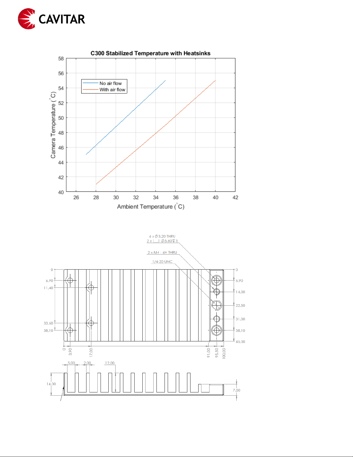
compared to the standard version. All tests have been made with Cavitar Welding Camera C300, but the
results and conclusions apply also to Cavitar Welding Camera C400 series. All results are indicative.
There are numerous different welding processes and welding environments. Therefore also the cooling
requirements can vary substantially from case to case. Typically the following sources of heat must be
dealt with:
•Internal heat load generated by the camera itself
•External heat load generated by elevated ambient temperature
•External heat load generated by the welding process
Due to the internal heat generated by the camera electronics, heat must be transferred from the camera
to an external heat sink even in normal ambient temperature (25 °C). In such a situation it is usually
sufficient to mount the camera from the sides with an articulated arm having a metallic clamp.
Cavitar Welding Cameras have built-in safety measures for warning about increasing camera temperature.
With C300 series the camera temperature is shown in Cavitar Capture software and warnings will be
displayed on the screen (see the C300 operation manual for more details). With C400 series warnings are
generated by a separate temperature warning unit (see the C400 operation manual for more details).
Appropriate cooling will increase the lifetime of the camera. However, at the same time it is important to
keep the camera temperature above dew point to avoid condensation. Depending on the total heat load
either passive cooling (Chapter 2) or active cooling (Chapter 3) is needed.
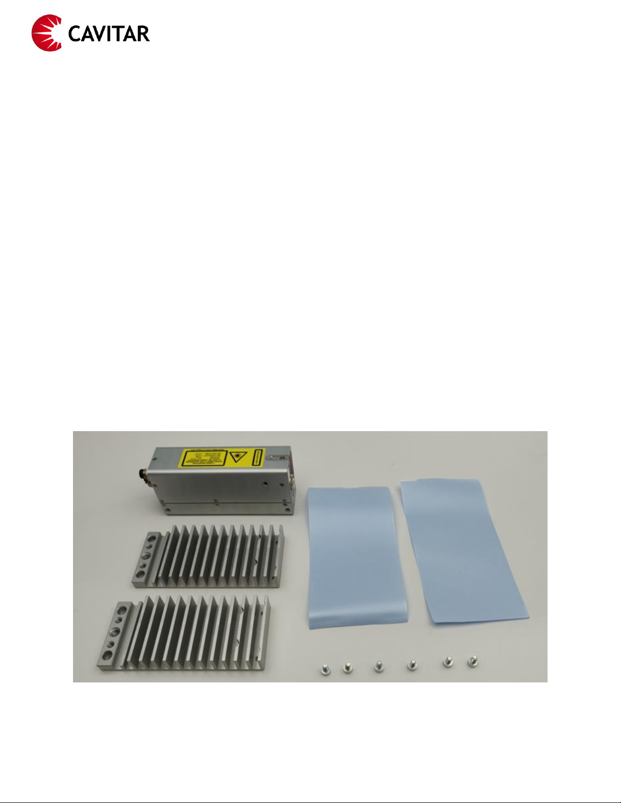
2. Passive cooling
Passive cooling is the simplest solution in situations where the external heat load is relatively small. As an
example we can consider a welding process with relatively short duration and small heat output under
ambient temperatures up to ~35 °C.
With passive cooling the aim is always to move the heat conductively from the camera to a separate heat
sink(s). In order to achieve efficient passive cooling the thermal conductivity from the camera to the heat
sink(s) must be maximized. The camera has been designed in such a way that the heat generated inside
the camera can reach the outer surface of the camera housing (especially both sides) as efficiently as
possible. This heat, as well as any additional external heat load, is then transferred to a heat sink(s).
Some important topics related to passive cooling are discussed in Sections 2.1 –2.3 in more detail.

Page 3of 22
2.1 Usage of thermally conductive sheets
High thermal conductivity sheets should be applied between the camera side(s) and the mounting and/or
heat sink(s) in order to maximize heat conductivity. Cavitar offers dedicated thermally conductive sheets
and heats sinks for passive cooling as optional accessories.
When applying thermally conductive sheets the following guidelines should be followed:
•Use only thin (up to 0.5 mm) sheets with high thermal conductivity
oCavitar offers thermally conductive sheets with the following specifications:
▪Thickness 0.2 mm
▪Thermal conductivity 6 W/mK
•Ensure the sheets are clean, sufficiently large (to cover the entire interface area) and unused
•Ensure the surfaces to be joined are properly cleaned
oDirt in the interface can prevent proper thermal contact between the surfaces
•Always ensure that possible protective foils are removed before use
oProtective foils typically have very poor thermal conductivity and if they are not removed,
heat transfer from camera to heat sinks(s) will be severely compromised
•Remember to apply thermally conductive sheets in all interfaces between the camera and the
final heat sink (e.g. welding machinery)
•Do not re-use thermally conductive sheets
In the following figures the usage of thermally conductive sheets is shown in detail in combination with
Cavitar heat sinks designed for C300.
Fig. 2.1. Components for the mounting of Cavitar heat sinks (model C300).

Page 4of 22
Fig. 2.2. Ensure the camera sides are clean.
Fig. 2.3. Remove the protective foil from the thermally conductive sheet (if applicable).

Page 5of 22
Fig. 2.4. Place the thermally conductive sheet over the camera and mark the locations of the threads.
Fig. 2.5. Place the heat sink over the thermally conductive sheet and mount the heat sink with three screws
(DIN912 M3x8).

Page 6of 22
Fig. 2.6. Heat sink mounted to the camera.
Fig. 2.7. Repeat the procedure for the other side.

Page 7of 22
Fig. 2.8. Remove excess sheet, if applicable.
Fig. 2.9. Heat sinks successfully mounted.

Page 8of 22
2.2 Mounting to machinery
The simplest and most compact passive cooling solution is to mount the camera to the welding machinery
with a thermally conductive mount. For optimal results the following guidelines should be followed:
•The mount should be made of high thermal conductivity material such as aluminium or copper
•The mount should cover the entire side of the camera (for maximal heat transfer the camera can
be mounted from both sides)
•Thermally conductive sheet should be applied between the camera side(s) and the mount(s) as
well as between the mount(s) and welding machinery
•The connection point of the mount to the welding machinery should be in such a location where
the temperature of the welding machinery is as low as possible (however, the temperature of the
heat sink mustn’t be so low that condensation could take place inside the camera). Possible
mounting locations could be e.g. the metallic body of the welding machinery (roughly at the
ambient temperature) or some cooled component/location of the machinery, if available
•The contact area between the mount and welding machinery should be sufficiently large
(preferably at least similar contact area as between the mount and the camera)
•It is possible to reduce the effect of external heat loads by adding thermal insulation around the
camera and the mount (e.g. thermally insulating sleeve)
2.3 Heat sinks
Cavitar offers dedicated heat sinks (see Section 2.2 for mounting details) that can be applied if passive
cooling is sufficient but there is no suitable mounting location in the welding machinery.
In principle proper mounting to machinery can be more efficient than using separate heat sinks since the
temperature of the welding machinery is typically not affected by the heat generated by the camera while
the separate heat sinks get warm. Gradually thermal equilibrium will be obtained when the heat sinks
receive the same heating power from the camera as what they release to the surrounding air.
Since the cooling is based on heat transfer from the heat sinks to the surrounding air, thermal insulation
around the heat sinks can’t be applied (unlike in Section 2.2). The efficiency of the heat sinks is improved
if air can flow properly at the surfaces of the heat sinks. This is shown in Fig. 2.10.
The mechanical dimensions of the heat sinks for Cavitar Welding Camera C300 are shown in Fig. 2.11.
Similar heat sinks are available for C400 series.

Page 9of 22
Fig. 2.10. Stabilized C300 camera temperature with heat sinks (with and without air flow).
Fig. 2.11. Mechanical dimensions of the heat sink for C300.

Page 10 of 22
3. Active cooling
Active cooling is the most efficient solution for challenging conditions (elevated ambient temperature,
large heat load from the welding process). The most common means of active cooling include air cooling
and liquid cooling. Since active cooling is typically used in challenging environments, it is crucial to ensure
continuous and sufficient flow of the coolant to the camera. A dedicated warning system is strongly
recommended to avoid damage to the camera in case of problems with the flow of the coolant.
Air cooling (Section 3.5) can be a practical solution for relatively challenging conditions if suitable
pressurized air is available. Liquid cooling (Section 3.6) is even more efficient and for the most extreme
conditions air and liquid cooling can be combined (Section 3.7).
3.1 Installation to camera
Figure 3.1 shows typical active cooling components (2x cooling connector, 2x cooling hose and 2x hose
clamp) before and after installation to the camera. First the cooling connectors are connected to the
threads of the camera unit (ensure O-rings are in place; maximum torque 1 Nm). Then appropriate cooling
hoses (inner diameter 6 mm) are connected to the cooling connectors with appropriate hose clamps.
Always ensure that the cooling connectors and cooling hoses are properly fastened and free from any
leaks. Leaking cooling liquid can get in contact with the back of the camera and may in the worst case
enter the camera, thus breaking the camera.
Fig. 3.1. Active cooling components before and after installation to the camera.

Page 11 of 22
3.2Thermal insulation from the environment
In high temperature environment the efficiency of cooling can be greatly improved by appropriate thermal
insulation of the camera and cables from the environment. This is especially important for the cables
which are not cooled as efficiently as the camera body. Various industrial thermally insulating protective
sleeves are available. In the figures below the following sleeves have been applied:
•ADL Insulflex Thermosleeve B
oFiber glass sleeve (flexible)
oContinuous temperature up to 540 °C
oSuitable for inner insulation layers (three layers applied in the tests)
•ADL Insulflex Pyrojacket
oFiber glass sleeve with silicone rubber coating
oContinuous temperature up to 260 °C
oShort-term (15 min) temperature up to 1090 °C
oMomentary (15 sec) temperature up to 1650 °C
oSuitable for the outermost insulation layer (one layer applied in the tests)
An alternative protective sleeve for Pyrojacket for the most challenging environments:
•ADL Insulflex Pyreflect firesleeve
oAramid fiber blanket with aluminium coating
oReflects at least 90 % of radiant heat energy
oContinuous temperature up to 340 °C
oShort-term temperature up to 540 °C
oMomentary (1 min) temperature up to 1650 °C
Before applying protective sleeves the proper cooling of electrical cables must be arranged. This can be
done by twisting the cooling hoses around the electrical cables as shown in Fig. 3.2.
Fig. 3.2. Twisting the cooling hoses around the electrical cables.
Since the cooling hoses can’t be twisted around the electrical cables right behind the camera, it is
important to wrap all hoses and cables tightly inside aluminium foil behind the camera. In Fig. 3.3 four
rounds of aluminium foil have been wrapped around the camera and all cables and hoses. The foil covers
roughly half of the camera housing and continues to the location where the cooling hoses can be properly
twisted around the electrical cables. Proper thermal contact to the camera housing is ensured by wrapping
Kapton tape tightly around the aluminium foil. Since the housing of the camera is kept cool by active
cooling, also the aluminium foil is kept cool and this keeps the cables cool in the region where the cooling
hoses can’t be properly twisted around the cables.

Page 12 of 22
Fig. 3.3. Aluminium foil wrapped around camera housing, cables and hoses.
Fig 3.4 shows the effect of the aluminium foil. In this test radiator cooling (see Section 3.6.2 for more
details) without camera insulation (but with cables insulated) was applied.
Fig. 3.4. Effect of aluminium foil on cable temperature.
The most efficient insulation arrangement is the following:
•Cooling hoses twisted around electrical cables
•Aluminium foil wrapped around camera housing as well as hoses and cables behind the camera
•Cables and camera insulated with several thermally insulating protective sleeves (with outermost
sleeve being air-tight)
•Low-pressure air blown through the system (in this case air must be able to exit the system
through appropriate opening between the camera housing and the outermost protective sleeve)

Page 13 of 22
If low-pressure air is not applied, it is important to seal the interface between the camera housing and the
outermost protective sleeve (e.g. with Kapton tape) in order to prevent hot ambient air from entering the
insulation. This is shown in Fig. 3.5.
Fig. 3.5. Interface between camera housing and outermost protective sleeve sealed with Kapton tape.
In many cases also less efficient insulation arrangements may be sufficient. As an example, in moderate
ambient temperatures it may not be necessary to insulate the camera housing. Therefore, if needed,
space can be saved by protecting only the cables with protective sleeves. This is shown in Figs. 3.6-3.8
(please note that the steps shown in Figs 3.2 and 3.3 have been carried out beforehand). In this example
effectively three layers of Thermosleeve B have been applied, but the appropriate number of layers can
be smaller or larger, depending on the ambient temperature and application.
Fig. 3.6. Thermosleeve B pulled over the cables and hoses.

Page 14 of 22
Fig. 3.7. Thermosleeve B wrapped around the cables and hoses (effectively two additional layers).
Fig. 3.8. Pyrojacket pulled over the cables and hoses and sealed to camera housing with Kapton tape.
Table 3.1 shows the effect of insulating the camera in addition to the cables. In this test recirculating
chiller cooling (see Section 3.6.3 for more details) was applied.
Table 3.1. Measured temperatures for insulated cables without/with insulated camera.
Temperature
Only cables insulated
Cables and camera insulated
Ambient (°C)
290
290
Camera body top side (°C)
80
52
Camera body bottom side (°C)
64
43
Cables (°C)
76
67
Camera (°C)
47
39
Cooling liquid (°C)
25
25
3.3Condensation
Condensation occurs whenever there is humidity in air and the temperature of an object falls below the
dew point. Condensation must be avoided since it can damage the welding camera. Condensation can be
prevented by keeping the cooling medium (air or liquid) temperature above the dew point. Usually
temperatures around 25…30 °C are safe in this respect. However, in exceptionally humid and warm
environments even higher cooling medium temperatures may need to be applied. Figure 3.9 shows the
dependence of dew point on ambient temperature and relative humidity in normal pressure.

Page 15 of 22
Fig. 3.9. Dependence of dew point on ambient temperature and relative humidity.
As an example, if the ambient temperature is 30 °C and relative humidity is 80 %, the temperature of
the coolant must be above 27 °C in order to avoid condensation. As can be seen from Fig. 3.9, it is
always safe (from the condensation point-of-view) to use coolant temperature at or above ambient
temperature. In this respect the radiator solution (see Section 3.6.2) is an easy way to avoid
condensation issues (provided that the radiator is located appropriately).

Page 16 of 22
3.4 About the tests
The tests were carried out by putting the camera and cables inside an oven and by logging temperature
values from different locations (Fig. 3.10). Also the ambient temperature inside the oven was measured.
Fig. 3.10. Temperature measurement points.
All tests were realized with 25 m long inlet and outlet cooling hoses (50 m total loop length) with inner
diameter of 6 mm. In the tests of Sections 3.5 and 3.6 the cables were insulated and the camera was not
insulated (see Figs. 3.2, 3.3 and 3.6-3.8) except in the recirculating chiller tests, which were done also with
the camera insulated (see Fig. 3.5). In the case of combined air and liquid cooling (Section 3.7) the
insulation consisted of one pyrojacket (no thermosleeves applied) and the interface between camera
housing and pyrojacket was not sealed (see Fig. 3.11) to let the air flow through the system. Cooling hose
twisting around cables (Fig. 3.2) and aluminium foil (Fig. 3.3) were applied also in this test.
Fig. 3.11. Insulation arrangement for combined air and liquid cooling.
Body top measurement point
Body bottom measurement point
Cables Temperature measurement point

Page 17 of 22
An example measurement is shown in Fig. 3.12, where the evolution of different temperatures as a
function of time can be seen. In this test recirculating chiller (constant cooling liquid temperature 25 °C)
was applied and both the cables and the camera were insulated.
Fig. 3.12. Evolution of temperatures (recirculating chiller, cables and camera insulated).
It is important to note that the results are indicative and valid only for the described test setup. The length
of insulation was less than 1 m and there was no heat load from arc process.

Page 18 of 22
3.5Air cooling
3.5.1 Pressurized air
Pressurized air can be applied simply by connecting the incoming air hose to either cooling connector of
the welding camera. The air will come out from the second cooling connector of the camera. This air can
be guided to desired location with a second hose (can also be utilized in air knife). If the camera and cables
are insulated (e.g. inside an air-tight thermally insulating protective sleeve such as pyrojacket), the
exhaust air can also be used for keeping the air inside the protective sleeve cooler. This is very useful in
keeping the cables sufficiently cool. In this case there is no need to connect anything to the second cooling
connector of the camera (the aluminium foil around the cables shouldn’t be applied in order not to
obstruct the exhaust air flow). The exhaust air can be forced to travel back inside the protective sleeve by
sealing the camera end of the insulation (see Figs. 3.5 or 3.8). Pressurized air should be sufficiently pure
(no water or oil) and the pressure shouldn’t be excessive. Ideal temperature for the pressurized air is
~25…30 °C (to avoid condensation and enable efficient cooling). Fig. 3.13 shows the maximum ambient
temperature (camera temperature reaching 55 °C) with different air pressures (cables insulated, camera
not insulated, see Figs 3.2, 3.3 and 3.6-3.8; return air not cooling the air inside the protective sleeve).
Fig 3.13. Maximum ambient temperature with different air pressures.
3.5.2 Vortex pipe
Vortex pipes can improve the efficiency of air cooling substantially. However, special attention must be
paid to avoid condensation and for this reason vortex pipes can only be considered if the user is
experienced with vortex pipes and can be certain that there is no risk of condensation. Otherwise same
principles as with conventional pressurized air apply.

Page 19 of 22
3.6Liquid cooling
3.6.1 Requirements and recommendations
•Cooling channels inside the camera are made of aluminium. Only use cooling liquids and cooling
equipment that are compatible with aluminium (to prevent corrosion). If the cooling circuitry
contains more noble metals than aluminium, the usage of magnesium anodes can be considered
•Always ensure that the cooling connectors and cooling hoses are properly fastened and free from
any leaks. Leaking cooling liquid can get in contact with the back of the camera and may in the
worst case enter the camera, thus breaking the camera
•A mixture of pure water and inhibited glycol is recommended to avoid corrosion and algae growth
oPure water can be distilled, demineralised, de-ionised or reverse osmosis water
oNever use pure water without inhibited glycol since this causes corrosion
oGlycol must be inhibited (to avoid corrosion) and the glycol content in the mixture must
be at least 20 volume % (to prevent algae growth)
oEthylene glycol has better cooling performance than propylene-based glycol but is more
toxic
oModern industrial glycols contain inhibitors alongside a pH buffer and biocide to prevent
corrosion, algae growth and rust
oNever mix different glycols
•The cooling system must be properly flushed and cleaned before adding suitable inhibited glycol
and pure water mixture as well as when the mixture needs to be changed
•Prevent any contamination of the cooling liquid and cooling circuitry
•Cooling solution with temperature and flow rate monitoring and alarm feature is recommended
•Regular maintenance intervals areneededto ensure proper operation(e.g. checking the condition
of filters and cooling liquid)
•Never use automotive antifreeze liquids
•The cooling connectors of the welding camera are designed for a cooling hose with an inner
diameter of 6 mm. Such hoses need approximately 30 ml of coolant for each meter. An additional
1 l of coolant is needed with the radiator solution (described in Section 3.6.2). If a recirculating
chiller is applied (Section 3.6.3), the amount of additional coolant depends on the chiller reservoir
volume
3.6.2 Radiator solution
Cavitar has made extensive empirical tests with active liquid cooling utilizing a radiator with fans and a
water pump. The cooling liquid is maintained in a temperature close to the ambient temperature at the
location of the radiator. Cavitar offers radiator cooling solution that is compatible with the aluminium
body of the welding camera.
Fig. 3.14 shows the results for the radiator solution with cables insulated and without camera insulation
(see Figs. 3.2, 3.3 and 3.6-3.8). Air temperature around the radiator was 24 °C and flow rate was 20 l/min.

Page 20 of 22
Fig. 3.13. Camera temperature as a function of ambient temperature (radiator solution).
3.6.3 Recirculating chiller
Recirculating chiller maintains the cooling liquid at the set temperature and is the most precise means of
liquid cooling (provided that the chiller is sufficiently powerful). The cost of the chiller is typically higher
than the cost of the radiator solution. Another important aspect with the chiller is to ensure that the
chiller can be used together with the welding camera since the cooling channels inside the camera are
made of aluminium (corrosion must be prevented). The results from the tests with recirculating chiller
were presented in Table 3.1 (reproduced below).
Table 3.1. Results with recirculating chiller (without/with camera insulation).
Temperature
Only cables insulated
Cables and camera insulated
Ambient (°C)
290
290
Camera body top side (°C)
80
52
Camera body bottom side (°C)
64
43
Cables (°C)
76
67
Camera (°C)
47
39
Cooling liquid (°C)
25
25
Other manuals for C300
1
This manual suits for next models
2
Table of contents
Other Cavitar Welding Accessories manuals
Popular Welding Accessories manuals by other brands

InterTest
InterTest iShot Weld-i HD 625 instruction manual

widos
widos HRG 6 Segment Working Instructions Translation

GYS
GYS GYSMATIC 9/13 XL user manual

Lincoln Electric
Lincoln Electric Innershield NR-131 datasheet

Leister
Leister Welding-Pen A operating instructions

PROFAX
PROFAX WP-500 operating instructions