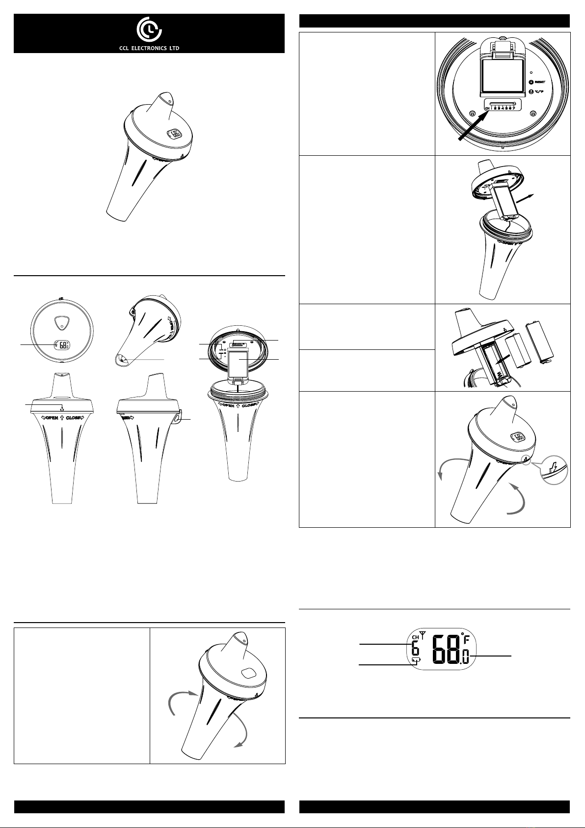
The icon blinks once every time when incoming wireless sensor
signal is received (every 60s)
Fair wireless sensor signal
Weak wireless sensor signal
Bad / no wireless sensor signal
3. If the signal for Ch 1~7 has discontinued and does not recover within 15 minutes, the
temperature and humidity will display “Er” for the corresponding channel.
4. If the signal does not recover within 48 hours, the “Er” display will become
permanent. You need to replace the batteries of the “Er” channel’s sensors and then
press [ SENSOR ] key to pair up with the sensors per each “Er” channel again.
NOTE:
The operation or signal icons of different display consoles may be different, please refer
to the user manual of your display console for more detail.
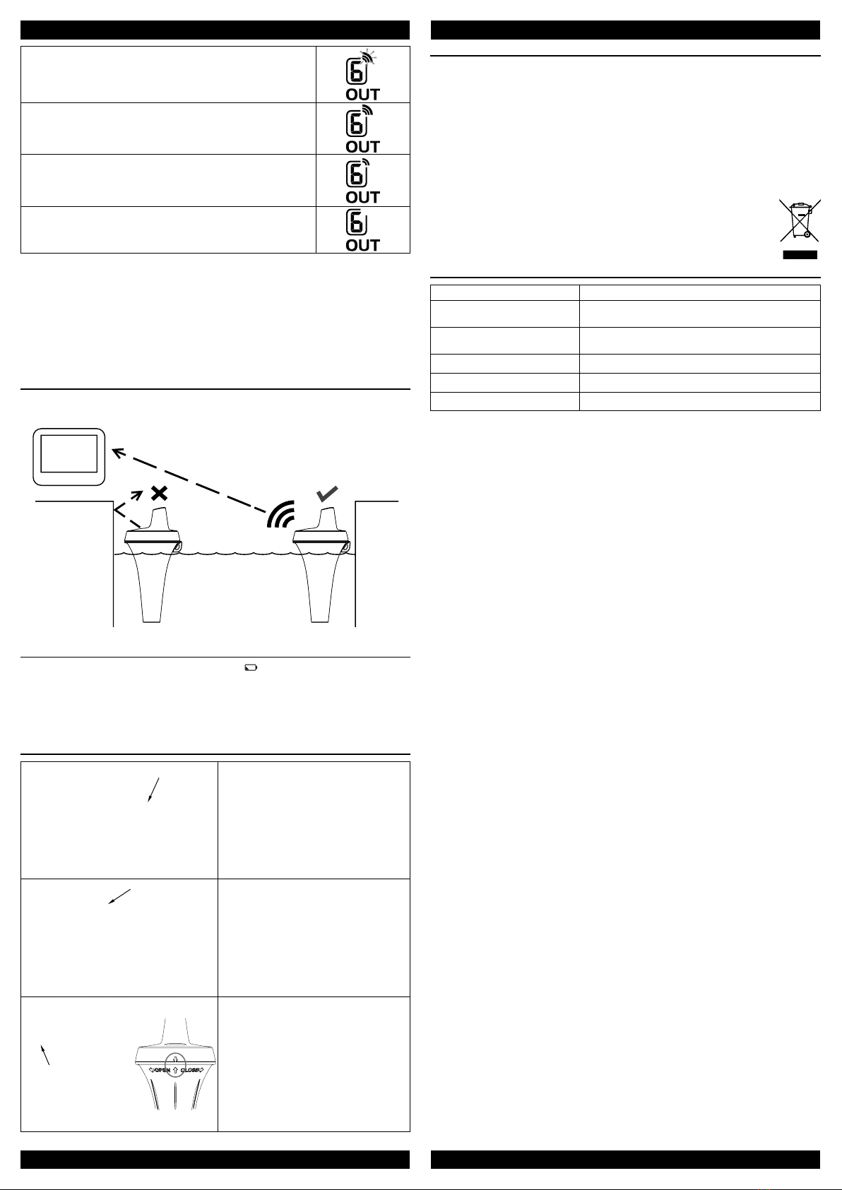
SENSOR PLACEMENT
Place the sensor in the pool within 30 meters (100 feet) of the display console and avoid
side wall of the pool block the sensor signal.
Display
console Pool sensor placement
LOW BATTERY ICON
If the sensor is low in battery, the low battery icon “ ” will display on the LCD of the
sensor and display console.
NOTE:
On the display console, the low battery icon will only appear when the corresponding
channel is displaying.
PRECAUTIONS WHEN OPENING AND CLOSING THE SENSOR CASING
Inner O-ring Outer O-ring 1. Opening the casing:
- Unscrew the bottom casing carefully in
direction indicated
- There are 2 o-rings , one inner and one
outer in blue color between the 2 casings
- The outer O-ring may drop down and
rest on the bottom casing.
Inner O-ring Outer O-ring 2. Before closing the casing:
- Ensure the unit is wiped dry completely
or leave to dry to avoid trapping any
moisture inside
- Carefully place both O-rings back into
their respective grooves, and apply
water-tightness jell/grease if necessary
Misplaced
outer O-ring
3. Closing the casing:
- Ensure the outer O-ring is not misplaced
(as shown) when closing the casing
- Close the casing tightly such that the
2 vertical arrows aligned vertically and
pointing to each other (circled in gray)
- Water droplets may condense on the
LCD if moisture is trapped inside the
unit. Just leave the unit open and let
the droplet evaporate naturally before
closing the casings
IMPORTANT NOTE
- Read and keep these instructions.
- Do not subject the unit to excessive force, shock, dust, temperature or humidity.
- Do not cover the ventilation holes with any items such as newspapers, curtains etc.
- Do not clean the unit with abrasive or corrosive materials.
- Do not tamper with the unit’s internal components. This invalidates the warranty.
- Only use fresh batteries. Do not mix new and old batteries.
- Do not dispose old batteries as unsorted municipal waste. Collection of such waste
separately for special treatment is necessary.
- Attention! Please dispose of used unit or batteries in an ecologically safe manner.
- Technical specications and user manual contents for this product are subject to
change without notice.
SPECIFICATIONS
Dimensions (W x H x D) 100 x 207.5 x 100 mm
Main power 2 x AA size 1.5V batteries
(Alkaline battery recommended)
Operating temperature range -5°C ~ 60°C ( -23°F ~ 140°F ) do not recommend
under freeze condition
RF frequency 915 MHz for US
RF Transmission interval 60 seconds
RF transmission range Up to 30 m (100 feet) line of sight
This device complies with Part 15 of the FCC Rules. Operation is subject to the
following two conditions: (1) this device may not cause harmful interference, and (2)
this device must accept any interference received, including interference that may cause
undesired operation.
Warning: Changes or modications to this unit not expressly approved by the party
responsible for compliance could void the user’s authority to operate the equipment.
NOTE: This equipment has been tested and found to comply with the limits for a Class
B digital device, pursuant to Part 15 of the FCC Rules. These limits are designed to
provide reasonable protection against harmful interference in a residential installation.
This equipment generates, uses and can radiate radio frequency energy and, if not
installed and used in accordance with the instructions, may cause harmful interference to
radio communications.
However, there is no guarantee that interference will not occur in a particular installation.
If this equipment does cause harmful interference to radio or television reception, which
can be determined by turning the equipment off and on, the user is encouraged to try to
correct the interference by one or more of the following measures:
- Reorient or relocate the receiving antenna.
- Increase the separation between the equipment and receiver.
- Connect the equipment into an outlet on a circuit different from that to which the
receiver is connected.
- Consult the dealer or an experienced radio/TV technician for help.