CCTV CCT730 User manual

CCT730
16-way Colour DVR
Instructions
April 2003 -Version 1.1

CCT730 V1.1
1
Warning Notes
lAll the safety and operating instructions should be read before the CCT730 is operated.
lAll the safety and operating instructions should be retained for future reference.
lEnsure all operating instruction and warning notes are complied with at all times.
lDo not use strong or abrasive detergents when cleaning the CCT730.
lThere are no user-serviceable parts inside. Please contact a qualified engineer for servicing
and maintenance.
lDo not expose the CCT730 to water or moisture and do not try to operate it in wet areas.
lPlease make sure that both ends of the power lead are plugged in.
lDo not drop foreign objects through the CCT730’s case or expose it to moisture.
lDo not attempt to disassemble the CCT730.
lContact a qualified engineer if the following situation happens:
ŸThe power lead or plug is damaged.
ŸThe CCT730 has been exposed to rain or water.
ŸThe CCT730 does not operate normally by following the operating instructions.
ŸThe CCT730 falls to the ground or its cover is damaged.
lWhen replacement parts are required, make sure that the service engineer has used
replacement parts specified by System Q Ltd or that these parts have the same
characteristics as the original ones. Unauthorized substitutions may result in fire, electric
shock, or other hazards.
lUse only with a mounting accessory recommended by System Q Ltd.
lNever push objects of any kind into the case of the CCT730 as they may touch dangerous
voltage points or short cut parts that could result in a fire or electric shock.
lIf an outside cable system is connected to the CCT730, be sure that the cable system is
grounded so as to provide some protection against voltage surges and built-in static
charges.
lAll normal precautions to avoid component damage due to electrostatic discharge should be
taken during installation and operation.
lTo prevent electric shock, do not remove screws or the unit’s cover.

CCT730 V1.1
2
CONTENTS
1. Features...................................................................................................................................................4
2. CCT730 Applications..............................................................................................................................4
3. Quick Installation Guide.........................................................................................................................5
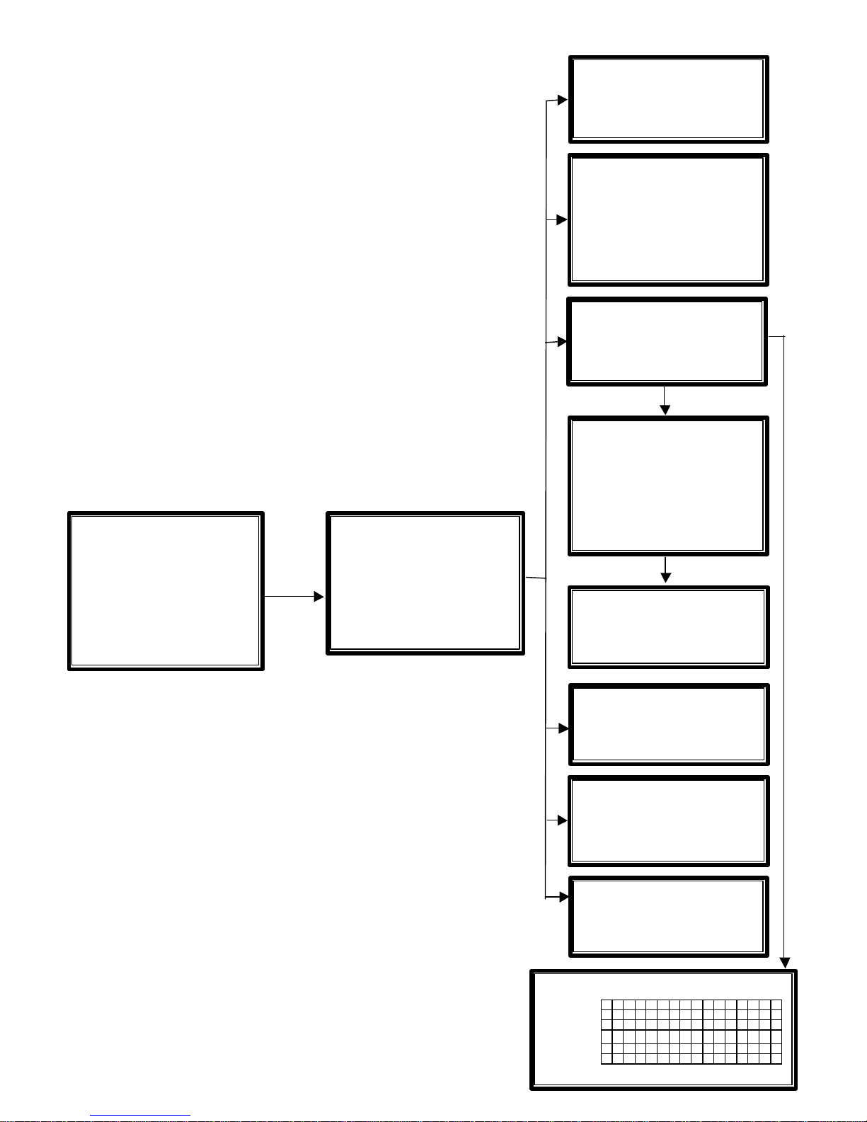
4. CCT730 Menus.......................................................................................................................................6
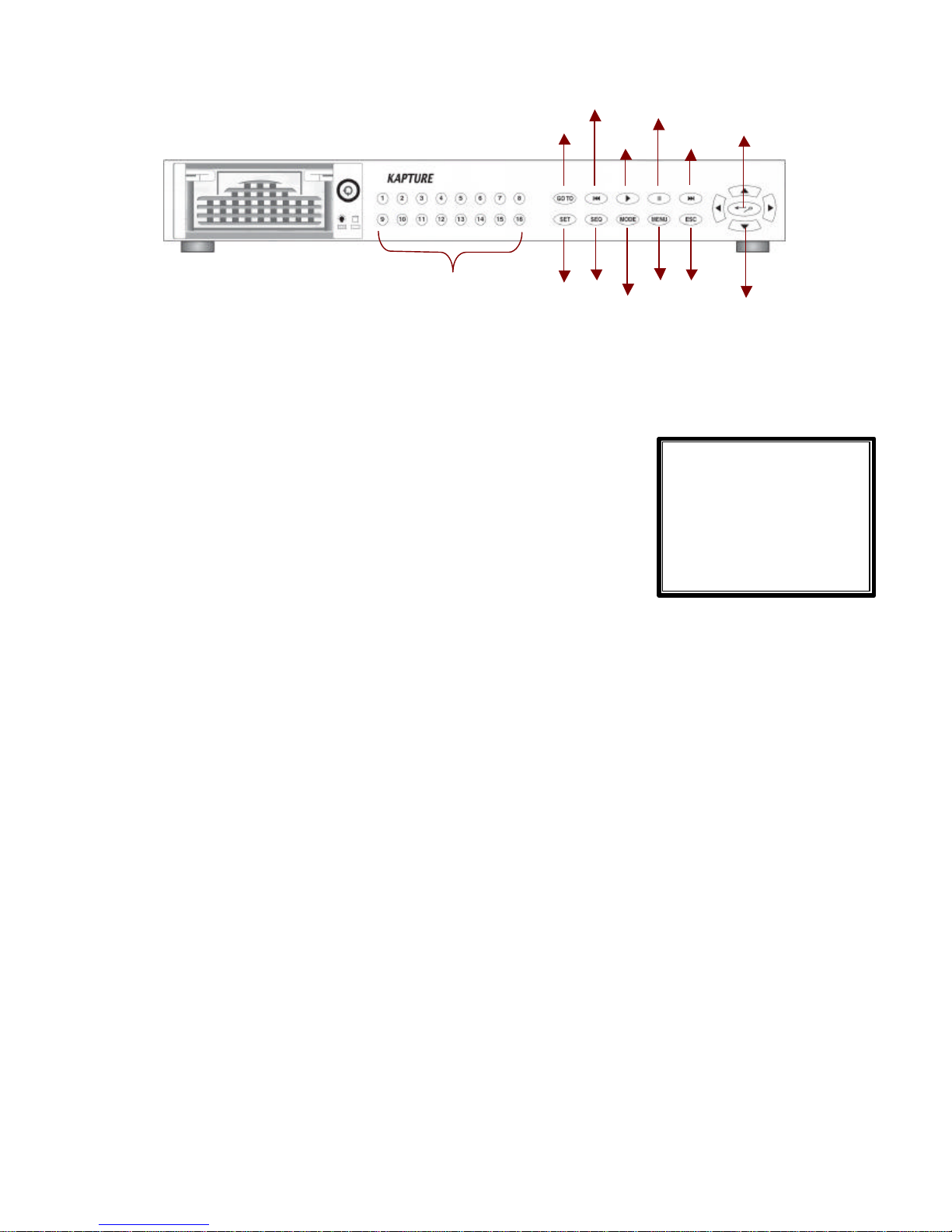
5. Front Panel..............................................................................................................................................9
6. Menu Set-up.........................................................................................................................................12
6.1 Event List....................................................................................................................................12
6.2 OSD/ Timer.................................................................................................................................12
6.2.1 OSD/ Timer -Date/ Time...............................................................................................12
6.2.2 OSD/ Timer -Date Display Mode................................................................................12
6.2.3 OSD/ Timer -Date/ Time Display................................................................................12
6.2.4 OSD/ Timer –PB Date/ Time Position........................................................................13
6.2.5 OSD/ Timer -RS485 Time Calibration........................................................................13
6.2.6 OSD/ Timer -Call Monitor Dwell..................................................................................13
6.2.7 OSD/ Timer -Text Colour..............................................................................................13
6.2.8 OSD/ Timer -Display Type...........................................................................................13
6.2.9 OSD/ Timer –OSD Display..........................................................................................13
6.3.Monitor Menu.............................................................................................................................13
6.3.1 Monitor -Video Setup....................................................................................................13
6.3.2 Monitor-Live Refresh Rate...........................................................................................13
6.3.3 Monitor -Screen Center Point.....................................................................................14
6.3.4 Monitor -Screen H-Size................................................................................................14
6.3.5 Monitor -Background Colour.......................................................................................14
6.3.6 Monitor -Show Colour Bar...........................................................................................14
6.4 Camera Menu............................................................................................................................14
6.4.1 Camera Configuration Table 1 .....................................................................................14
6.4.2 Camera Auto-Detect......................................................................................................16
6.4.3 Camera Title....................................................................................................................16
6.4.4 Power ON Detect...........................................................................................................16
6.4.5 Title Position....................................................................................................................16
6.5 Record.........................................................................................................................................17
6.5.1 Day/ Night........................................................................................................................17
6.5.2 Weekend..........................................................................................................................17
6.5.3 REC Event Only.............................................................................................................18
6.5.4 Event CH Priority............................................................................................................18
6.5.5 Circular Record...............................................................................................................18
6.5.6 HDD FullAlarm...............................................................................................................18
6.6 Event...........................................................................................................................................19
6.6.1 Day/ Night Switch...........................................................................................................19

CCT730 V1.1
3
6.6.2 Event Response.............................................................................................................19
6.6.3 Motion Detect..................................................................................................................20
6.6.4 Alarm In............................................................................................................................22
6.6.5 Video Loss Detect..........................................................................................................22
6.6.6 Alarm Set/ Reset SW.....................................................................................................22
6.6.7 Release Time..................................................................................................................22
6.6.8 Clear Event List..............................................................................................................22
6.7 Others..........................................................................................................................................23
6.7.1 RS-485 ID Set Up ..........................................................................................................23
6.7.2 RS-485 Protocol.............................................................................................................23
6.7.3 Software Information.....................................................................................................23
6.8 Save/ Load Default....................................................................................................................23
6.9 Engineer Set Up ........................................................................................................................24
6.9.1 Change Password..........................................................................................................24
6.9.2 Covert Cam Visible........................................................................................................24
6.9.3 Playback Check..............................................................................................................24
6.9.4 Language.........................................................................................................................24
6.9.5 Format Hard Disk...........................................................................................................24
6.9.6 System Colour ................................................................................................................24
6.10 Shutdown..................................................................................................................................24
6.11 Exit.............................................................................................................................................24
7. Windows Application Software ..........................................................................................................25
7.1 Connecting the Caddy to a PC................................................................................................25
7.2 Download the Software ............................................................................................................26
7.3 Function Buttons........................................................................................................................26
8. Connectors ...........................................................................................................................................28
9. CCT730 Specification.........................................................................................................................31
Appendix 1: Hard Disk Error Message.................................................................................................32
Appendix 2: Supported HDD..................................................................................................................33
Appendix 3: Estimated Recording Times.............................................................................................34

CCT730 V1.1
4
1. Features
lPowerful Wavelet compression
lProprietary real time Operating System.
lDuplex operation: View live video and playback simultaneously
lSupport NTSC and PAL system
lProgrammable recording picture rate (up to 60 pics per sec)
lRecording priority of each camera dynamically adjusted by motion detection
lHot swappable Hard Disk Drive
lWindows compatible Data format
lPowerful Alarm Processor allows flexible alarm trigger and response configuration
lProgrammable motion detection area and sensitivity for each individual camera
lDifferent motion sensitivities available for day and night time
lIntelligent algorithm refreshing main monitor display dynamically
lUser-friendly video search
lVersatile multiple-windows display format
lPassword to secure installation authorization
lSystem auto reboot after power interruption
lSystem software stored in non-volatile memory, free from hard disk crash
2. CCT730 Applications
CCT730 is a cost-effective and easy-to-use multiplexed digital video recorder, equipped with a
proprietary real time operating system, powerful Wavelet compression engine, duplex
multiplexer and a hot swappable Hard Disc Drive.

CCT730 V1.1
5
3. Quick Installation Guide
The CCT730 is equipped with ahot-swap Hard Disk Drive (HDD) that canbe exchangedwhen
itis full. The following photos illustrate how to install the HDD into its removable caddy.
1) Pull the exterior handle towards youand unlock with the
key provided.
2) Pull the handle outwards until the caddyis free from the
case of the CCT730.
3) Push the release latch to slide the top cover backwards
and remove the HDD.
4) Insert the DC power cable and IDE cableinto the HDD.
Make sure the HDD is set to“Master”.
5) Position the empty HDD into the caddyand slide the top
cover back to secure. Secure the HDD using the screws
provided.
6) Slide the caddyback into the CCT730 case and lock it
with the key provided.

CCT730 V1.1
6
4. CCT730 Menus
MAIN MENU
1 Event List
2 OSD / Timer
3 Monitor
4 Camera
5 Record
6 Event
7 Others
8 Save / Load Default
9 Engineer
10 Shutdown
11 Exit
OSD / Timer
2
1 Date / Time
2 Date Display Mode Y/M/D
3 Date / Time Display 2Rows
4 Date / Time Position
5 PB Date / Time Position
6 RS485 Time Calibration
7Call Monitor Dwell 5
8Text Colour 7
9Display Type 1
10 OSD T&D/T
11 EXIT
Date / Time 2
-
1
1 Year 2002
2 Month 12
3 Date 4
4 Hour 16
5 Minute 5
6Second 20
7 Week MON
8 Exit / Update
9 Exit / Without Update
Monitor 3
1 Brightness 125 IIIIIIIII
2 Contrast 190 IIIIIIIII
3 Saturation 188IIIIIIIII
4 Hue 133 IIIIIIIII
5 Live Refresh Rate Auto
6 Screen Center Point
7 Screen H-Size
8 Background Colour
2
9 Show Colour Bar
10
Exit
Camera 4
1 Configuration Table 1
2 Camera Auto-Detect
3 Camera Title
4 Power ON Detect ON
5 Title Position Default
6 Exit
Camera Title
4
-
3
1 Camera_ 1 10 Camera_10
2 Camera_ 2 11 Camera_11
3 Camera_ 3 12 Camera_12
4 Camera_ 4 13 Camera_13
5 Camera_ 5 14 Camera_14
6 Camera_ 6 15 Camera_15
7 Camera_ 7 16 Camera_16
8 Camera_ 8 17 Exit
9 Camera_ 9
Configuration Table 1
4
-
1
12345678910
11
12
13
14
15
16
Install V
V
VV
V
VV
V
VV
V
VV
V
VV
Covert ................
Termination V
V
VV
V
VV
V
VV
V
VV
V
VV
Gain Control 8888888888888888
Call Seq 12345678910
11
12
13
14
15
16
Event
List
1
1 02/10/21 15:58:53 M12
2 02/10/21 18:24:30 A 3
3 02/10/22 10:19:16 L16
---Continue---
Record 5
1 Day / Night
2 Weekend
3 REC Event Only OFF
4 Event ChPriority Auto
5Circular Record ON
6 HDD Full Alarm ON
7 Exit
Day / Night
5
-
1
1 Day Start Time 08:00
2 Day Stop Time
20:00
3 Day REC PPS 60
4 Day REC Quality Normal
5 Night REC PPS 60
6 Night REC Quality Normal
7 Exit
Weekend 5
-
2
1 Weekend Setting OFF
2 Start FRI
3 Stop MON
4 REC PPS 60
5 REC Quality Normal
6 Exit
INPUT PASSWORD
1 Input Password 0 0 0 0
2 Enter Main Menu
3 Exit
Camera_1
! ”
# $ % & ( ) * + , _ . /
0 1 2 3 4 5 6 7 8 9 : : < > ?
@ A B C D E F G H I J
K L M N O
P Q R S T U V W X Y Z [ \
] ^ _
‘
abcdefghijklmno
pqrstuvwxyz{|}~

CCT730 V1.1
7
Day / Night Switch 6
-
1
1 Day / Night SW Enable
No
2 Switch<OFF>
Day
3 Delay For Active
60
4 Exit
Event
Response
6
-
2
1 Internal Buzzer ON
2 Event Relay Output ON
3 Event List ON
4 Event Full Screen OFF
5 Call Event Display ON
6 Response Duration 10
7 Any Key To Stop ON
8 Exit
Motion Detect
6
-
3
1 Motion Detect OFF
2 Configuration Table 2
3 Condition Set Up
4 Exit
Alarm In
6
-
4
1 Alarm In Detect OFF
2 Configuration Table 2
3 Exit
Release Tim
e
6
-
7
1 Motion RES Time 2
2 Video Loss RES Time 2
3 Alarm In RES Time 10
4 Exit
Clear
Event
List 6
-
8
1 Clear Event List: No
2 Clear Event List: Yes
3 Exit
Event
6
1 Day / Night Switch
2 Event Response
3 Motion Detect
4 Alarm In
5 Video Loss Detect
Dis
6 Alarm Set / Reset SW
En
7 Release Time
8 Clear Event List
9 Exit
MAIN MENU
1 Event List
2 OSD / Timer
3 Monitor
4 Camera
5 Record
6 Event
7 Others
8 Save / Load Default
9 Engineer
10 Shutdown
11 Exit
Configuration Table 2
6
-
4
-
2
12345678910
11
12
13
14
15
16
Alm In Type O
O
OO
O
OO
O
OO
O
OO
O
OO
Day: Alm In V
V
VV
V
VV
V
VV
V
VV
V
VV
Day: Motion V
V
VV
V
VV
V
VV
V
VV
V
VV
Night: Alm In V
V
VV
V
VV
V
VV
V
VV
V
VV
Night: Motion V
V
VV
V
VV
V
VV
V
VV
V
VV
ESC For Return
C
ondition Set Up
6
-
3
-
3
1 Camera_ 1 10 Camera_10
2 Camera_ 2 11 Camera_11
3 Camera_ 3 12 Camera_12
4 Camera_ 4 13 Camera_13
5 Camera_ 5 14 Camera_14
6 Camera_ 6 15 Camera_15
7 Camera_ 7 16 Camera_16
8 Camera_ 8 17 Exit
9 Camera_ 9
Camera_1 6
-
3
-
3
1 Detect Area
2 Sensitivity
3 Exit

CCT730 V1.1
8
Save Installer Setting
8
-
2
1 Save / Load: No
2 Save / Load: Yes
3 Exit
Others
7
1 RS-485 ID Setu
p 224
2 RS-485 Protocol
3 Software Information
4 Exit
Save / Load Default
8
1 Load Installer Setting
2 Save Installer Setting
3 Load Factory Setting
4 Load Factory Password
5 Exit
Engineer
9
1 Change Password 9999
2 Covert Cam Visible No
3 Playback Check OFF
4 Language English
5Format Hard Disk
6System Colour
Colour
7 Exit
Exit 1
1
1 Set Up Data: Save
2 Set Up Data: Cancel
3 Exit
RS
-
485 Protocol
7
-
2
1Baud Rate: 9600
2 Bits: 8
3 Stop: 1
4 Parity: None
5 Exit
Load Installer Setting 8
-
1
1 Save / Load: No
2 Save / Load: Yes
3 Exit
Load Factor Setting
8
-
3
1 Save / Load: No
2 Save / Load: Yes
3 Exit
Format
Hard
Disk
9
-
5
1 Format Hard Disk: No
2 Format Hard Disk: Yes
3 Exit
MAIN MENU
1 Event List
2 OSD / Timer
3 Monitor
4 Camera
5 Record
6 Event
7 Others
8 Save / Load Default
9 Engineer
10 Shutdown
11 Exit
Software Information
7
-
3
1 CPU Filename D6SE0100
2 FPGA Filename FPGA0505
3 Date 2003/01/23
4 Video System NTSC
5 DSP BD HW SK1V3302
6DSP BD SW SK1V3300
7Exit
Shutdown 10
1Shutdown: No
2Shutdown: Yes
3Exit
CCT730
It is now safe to
remove power

CCT730 V1.1
9
GOTO
1 Minute 30
2 Hour 20
3 Day 21
4 Month 11
5 Year 02
5 Goto Begin
6 Goto End
7 Exit
5. Front Panel
*CCT730 starts recording automatically after power is on.
CHANNEL 1~16
Press one of these buttons to view the a camera image in full screen.
GOTO
In playback mode, you can press the GOTO button to access the
GOTO menu. This menu allows you to search for certain recorded
images by entering the date and time.
You can either use the arrows buttons on the front panel to move
down to the “5 GoTo Begin” option and press the ENTER button to
take you to the start of the recorded images; or move down to the “6
GoTo End” option and press ENTER to go to the end of the recording.
FAST REWIND Itt
1. Whilst in playback mode, press this button to rewind through the recorded images. Press it
again to increase the rewind speed: x1, x2, x4 and x8.
2. In playback mode, you can also press and hold this button for 3 seconds to move
automatically to the beginning of the recording.
PLAY/STOP u
1. When in Live mode, press this button to start to playback recorded images.
2. In playback mode when the PLAY button is illuminated, press this button to stop playing the
images and start recording.
PAUSE II
Press this button to pause a recorded image or to freeze live video, the PAUSE button will
illuminate.
FAST FORWARD uuI
1. Whilst in playback mode, press this button fast forward through the recordrd images. Press it
Channels 1-16
GOTO
Directional Arrow Keys
Enter/Zoom
Pause
Play/Stop
Fast Rewind
F/Forward
SET SEQ MODE
MENU
ESC

CCT730 V1.1
10
Sequen
ce_1 Set Up
1Pages 16
11 Page 8 5
2Mode 0
12 Page 9 5
3Timer Ind.
13 Page 10 5
4P
age 1 5 14 Page 11 5
5P
age 2 5 15 Page 12 5
6P
age 3 5 16 Page 13 5
7P
age 4 5 17 Page 14 5
8Page 5 5 1
8 Page 15 5
9P
age 6 5 19 Page 16 5
10 Page 7 5 20 Exit
again to increase the fast forward speed: x1 x2, x4 and x8.
2. In playback mode, you can also press and hold this button for 3 seconds to move
automatically to the end of the recording.
ENTER / ZOOM 8
1. In the menu screens, this button is used to “ENTER” a sub-menu or to confirm a command.
2. In full-screen mode where a live or recorded image is being displayed in full-screen, you can
also use this button to zoom (x2) into the image and then use the arrow buttons on the front
of the unit to move around the “zoomed” image. In this mode the button will be illuminated.
SET
In a split-screen display, press this button to enter SET mode where each of your cameras can
be assigned a Channel. These will relate to the Channel numbers/buttons on the front display of
the CCT730. The SET menu will appear with a cursor flashing over the first image/window. Use
the arrow buttons tupq to move the cursor to the desired camera image and then press the
desired CHANNEL or Number button to assign the camera. The cursor will move on to the next
window automatically. Press the ESC button to exit this mode.
SEQ
1. Press this button to start sequencing through the camera images
and press it again to stop sequencing. The SEQ button will be
illuminated as well as the camera channel on display when the
unit is in sequencing mode.
2. A number of different sequencing options can be obtained with the
CCT730. These options are set up using a menu, which can be
accessed by pressing the SET button whilst in the sequencing
mode.The number at the top of the menu indicates which Sequence you are setting up.
Pages -this allows you to decide the total number of pages/images to be used in the
sequence. The maximumvalue is 16, which means that each sequence can have up to 16
pages/images.
Mode -this item allows you to decide which display mode will be used in this sequence.
“0“represents full screen mode and “7”represents the 16-windows mode.
Sequence Timer -this item allows you to select “Com”or “Ind”Sequence Timer. “COM”
means every page in this sequence has a common dwell time; whilst IND means that each
page can havean individualdwell time.
Dwell Time and Page Setup –this allowsyou to set up the dwell time of each page. If the
sequence timer is selected as “COM”, once yuou change the dwell time of one page, the
dwell time of all the other pages will be changed as well. If the sequence timer is selected
as “IND”, the dwell time value can be changed individually page by page.
Using the arrow keys, move the cursor down to one of the page numbers and use the

CCT730 V1.1
11
right/ left arow buttons to change the dwell time or press the ENTER button for page setup.
MODE
Press this button to select your chosen display format (4,7,9,10,13 or 16 windows). The
camera buttons of all the selected cameras will be illuminated.
MENU
Press this button to enter the on-screen set-up menus (the button will be illuminated).
ESC
In the menu screens, press this button to return to previous menu.
DIRECTION ARROWS tupq
These buttons function as directional controls in the Zoom mode and on the menu screens.

CCT730 V1.1
12
MAIN MENU
1Event List
2 OSD / Timer
3 Monitor
4 Camera
5 Record
6 Event
7 Others
8 Save / Load Default
9 Engineer
10 Engineer
11 Exit
Event
List
1 02/10/20 08:12:39 L16
2 02/10/22 12:38:21 A3
3 02/10/22 15:58:53 M12
---Continue---
OSD / Timer
1 Date/ time
2 Date Displ
ay Mode Y/M/D
3 Date/ Time Display 2 Rows
4 Date/ Time Position
5 RS485 Time Calibration
6 Call monitor Dwell 5
7 Text Colour
8 Display Type 1
9 OSD Display
T&D/T
10 Exit
Date / Time
1 Year
2002
2 Month
12
3 Date
4
4 Hour
16
5 Minute
5
6 Second
20
7 Week
MON
8 Exit / Update
9 Exit / Without Update
6. Menu Set-up
The CCT730 menu set-up is hierarchical and is displayed in the initial
pages of this document. The menus allow you to configure the unit
according to the applictation yu will be using it for. Many functions can
be selected via these menus.
To enter the main menu, press the MENU button on the CCT730’s
front panel, the main menu will appear with a cursor over the first item.
This cursor can be moved using the up/down buttons on the front
panel. If you wish to exit the menu at any time, you may either select
the last item on the menu “EXIT” and then press ENTER button or
simply press the ESC button on the front panel of the CCT730.
6.1 Event List
This item allows you to enter the Event List. Up to 255 alarm events
will be logged in the unit’s non-volatile memory on a “First In, First
Out” basis, so the latest events always remain on the list.
6.2 OSD/ Timer
This menu item allows you to set the current date/ time, and other
On-Screen-Display (OSD) parameters. Press the ENTER button to
enter the date/time sub-menu.
6.2.1 OSD/ Timer -Date/ Time
Items 1~7 allow you to set thedate and time, use the right/ left buttons
to adjust the CCT730 to the accurate time.
If you want to save the modifications, move the cursor to the Exit/
Update optionand press Enter, your settings will be memorized. If you
don’t want to save the modifications, move the cursor to the Exit /
Without Update and press the Enter button, your adjustments will be
discarded.
6.2.2 OSD/ Timer -Date Display Mode
This item allows you to select a format of date display. You may use the right/ left arrow buttons
to choose from: Year/Month/Day, M/D/Y and D/M/Y.
6.2.3 OSD/ Timer -Date/ Time Display
This item allows you to select from a one or two row date/time display.

CCT730 V1.1
13
Monitor
1 Brightness 125
IIIIIIII
2 Contrast 190
IIIIIIII
3 Saturation 188
IIIIIIII
4 Hue 133
IIIIIIII
5 Live Refresh Rate
Auto
6 Screen Center Point
7 Screen H-Size
8 Background Colour
9 Show Colour Bar
10 Exit
6.2.4 OSD/ Timer –PB Date/ Time Position
This item allows you to move thecurrent Date/ Time Display to any position on your screen. Use
the directional arrow buttons to move the Date/ Time display around your screen.
6.2.5 OSD/ Timer -RS485 Time Calibration
RS-485 is used for multi-point communications: many devices can be connected to the same
bus. Move to this item and press the ETNER button, all CCT730 timers will be synchronized.
6.2.6 OSD/ Timer -Call Monitor Dwell
The call monitor display is always full screen switching of all the installed cameras, this item
allows you to set the Dwell Time between switching. The timer value ranges from 1 to 255
seconds.
6.2.7 OSD/ Timer -Text Colour
This item allows you to select from 16 different colours for the Date/ Time display.
6.2.8 OSD/ Timer -Display Type
This item allows you to select one from 6 different text types (reverse, bold…) for the Date/ Time
display.
6.2.9 OSD/ Timer –OSD Display
This item allows you to select which information you wish to display; you can choose from
•T&D/T(camera title and date/time); ‚Title; ƒD/T(date/time); „OFF.
6.3.Monitor Menu
This menu allows you to adjust the quality of the displayed image.
6.3.1 Monitor -Video Setup
Items 1~4 involve adjusting the brightness, contrast, saturation and hue of the attached
cameras. Use the front panel arrow buttons to adjust these values.
6.3.2 Monitor-Live Refresh Rate
This item allows you to set-up the camera refresh rate on the Main monitor; use the right/ left
arrow buttons to select between Fix or Auto. “Fix” means each camera has the same refresh
rate. “Auto” means the camera where more motion is detected will receive a higher refresh rate
automatically.

CCT730 V1.1
14
Camera
1 Configuration Table 1
2 Camera Auto-Detect
3 Camera Title
4 Power ON Detect ON
5 Title Position Defa
ult
6 Exit
6.3.3 Monitor -Screen Center Point
This item allows you to move the center point of the main monitor. Use the arrow buttons to
move the monitor center point. Press the ESC button to exit when finished.
6.3.4 Monitor -Screen H-Size
This item allows you to change the horizontal size of the displayed image. Press the right/ left
arrow buttons to adjust this.
6.3.5 Monitor -Background Colour
This item allows you to select from 16 different colours for the background colour of •
video-loss, ‚un-installed cameras andƒcovert situations.
6.3.6 Monitor -Show Colour Bar
This function allows you to fine tune the monitor’s performance using a colour bar pattern
generated by the CCT730.
6.4 Camera Menu
This menu allows you to adjust camera-related items, ex. Camera title,
Power On Detect, etc.
6.4.1 Camera Configuration Table 1
Configuration Table 1 allows you to configure 5 parameters for each individual camera.
Install
This item allows you to install individual cameras with each one being installed by default. Any
camera can then be un-installed manually. Once un-installed, all related functions are disabled.
v= camera installed •= camera not installed
Covert
This item allows you to make each camera’s input invisible (covert) on both the main and call
monitors, while the unit continues to record all the camera images. This is ideal where cameras
Configuration Table 1
12345678910
11
12
13
14
15
16
Install VVVVVVVVVVVVVVVV
Covert ················
Termination VVVVVVVVVVVVVVVV
Gain Control
8888888888888888
Call Seq 12345678910
11
12
13
14
15
16
ESC For Return

CCT730 V1.1
15
are installed covertly. The default setting is to have every camera visible.
v= covert •= not covert
Termination
This allows you to enable or disable the video loop-through output for each camera channel. If
the camera loop-through is not used, this setting should be enabled to get correct signal
termination. This is the default condition.
v= Termination enabled •= Termination disabled
Gain Control
This item allows you to adjust the camera’s video level. You may adjust the value between 1
and 16 for each camera.
REC Priority
This item allows the user to set the recording priority for each camera under a normal state (No
alarm occurred). TheCCT730 will record the camera that is assigned with a higher priority more
frequently. The user can move the cursor and use the ENTER key to adjust the value. The value
ranges from 1 to 16; “1” stands for the lowest priority; “16” stands for the highest priority. If the
camera is not installed, the priority will be set to 0 automatically.
Alarm REC Priority
This item allows you to set the recording priority when an alarm is triggered for the current
channel, either by Alarm In or by Motion.
For example:
If you set the PPS rate to “30”, the record priority of the channel to level ”4”, and the record
priority of all the other channels to level “1’, then each channel’s PPS can be calculated by the
formula below.
Situation 1: No alarm event occurs.
Channel 1 PPS = 31.6
1
1
1
1
1
1
1
1
1
1
1
1
1
1
1
4
4
*30 =
+
+
+
+
+
+
+
+
+
+
+
+
+
+
+
Channel 2 PPS = 58.1
1
1
1
1
1
1
1
1
1
1
1
1
1
1
1
4
1
*30 =
+
+
+
+
+
+
+
+
+
+
+
+
+
+
+
Channel 3 PPS = 58.1
1
1
1
1
1
1
1
1
1
1
1
1
1
1
1
4
1
*30 =
+
+
+
+
+
+
+
+
+
+
+
+
+
+
+

CCT730 V1.1
16
Camera Title
1 Camera_1 10 Camera_10
2 Camera_2 11 Camera_11
3 Camera_3 12 Camera_12
4 Camera_4 13 Camera_13
5 Camera_5 14 Camera_14
6 Camera_6 15 Camera_15
7 Camera_7 16 Camera_16
8 Camera_8 17 Exit
9 Camera_9
Camera_1
! ”
# $ % & ( ) * + , _ . /
0 1 2 3 4 5 6 7 8 9 : : < > ?
@ A B C D E F G H I J K L M N O
P Q R S T U V W X Y Z [ \
] ^ _
‘
abcdefghijklmno
pqrstuvwxyz{|}~
Situation 2:An alarm event occurs on channel 2.
Channel 1 PPS = 61.4
1
1
1
1
1
1
1
1
1
1
1
1
1
1
8
4
4
*30 =
+
+
+
+
+
+
+
+
+
+
+
+
+
+
+
Channel 2 PPS = 23.9
1
1
1
1
1
1
1
1
1
1
1
1
1
1
8
4
8
*30 =
+
+
+
+
+
+
+
+
+
+
+
+
+
+
+
Channel 3 PPS = 15.1
1
1
1
1
1
1
1
1
1
1
1
1
1
1
8
4
1
*30 =
+
+
+
+
+
+
+
+
+
+
+
+
+
+
+
Call Seq
The Call monitor sequence mode has 16 programmable steps. This item allows you to assign a
camera for each programmable step (1~16), “0” means skip this step. Those cameras, which
are not installed or are set as covert will not be displayed on the call monitor.
6.4.2 Camera Auto-Detect
The CCT730 is able to auto-detect which and how many cameras are connected to it by looking
for their video signal. If a camera channel is not used, it is recommended that it is set as “not
installed”. Otherwise that channel will detected as suffering from “video loss”. Move back to the
Configuration Table 1 menu to un-install a camera.
6.4.3 Camera Title
Each camera can be assigned a title up to 12 characters long. The
default title for each camera is their channel number, eg, Camera_1.
Move the cursor to the Camera Title option and press ENTER, the list
of camera titles will appear. Select a channel and press ENTER again,
the character sub-menu will appear.
Use the arrow buttons to select your chosen character and press
ENTER to add it to the title. If the wrong character is entered, the
MODE button on the front panel of the CCT730 also doubles as a
backspace key. NB. the first character on the full list of characters is a
space.
6.4.4 Power ON Detect
This item allows you to enable /disable the camera auto-detection when the power is on. The
default setting is ON.
6.4.5 Title Position
The camera title can be placed in one of five positions in the display window: Default, Top-R
(top-right), Top-L (top-left), Bom-R (bottom-right) and Bom-L (bottom-left).

CCT730 V1.1
17
Record
1 Day / Night
2 Weekend
3REC Event Only
OFF
4 Event CH Priority
Auto
5Circular Record
OFF
6 HDD Full Alarm Out ON
7Exit
Day / Night
1 Day Start Time 08:00
2 Day Stop Time 18:00
3 Day REC PPS 60
4 Day REC Qualit
y Normal
5 Night REC PPS 60
6 Night REC Quality Normal
7 Exit
Weekend
1 Weekend Setting
OFF
2 Start FRI
3 Stop MON
4 REC PPS 60
5 REC Quality Normal
6 Exit
6.5 Record
This menu allows you to set up all the parameters related to the
recordings that you wish to make.
6.5.1 Day/ Night
This menu allows you to set up the Day start/ stop time, the PPS
(Picture Per Second) and the recording quality for Dayand Night-time.
Day Start Time/ Day Stop Time
These two items allow you to set the start/ stop time of the daytime recording schedule. Use the
arrow buttons to select the desired start/ stop time and press ENTER to save the setting.
Day REC PPS/ Night REC PPS
These two items allow you to set the Day/ Night record PPS (Pictures Per Second). The higher
the number of pictures per second, the smoother the video playback appears but the more
storage space is taken up on the hard drive.
Day REC Quality/ Night REC Quality
These two items allow you to set up the Day/ Night record quality. A superior picture quality
affects playback but will fill the hard disk faster and the total record time will be shorter. Options
are Low, Normal, High and Super. See Appendix 3 for a more comprehensive list of estimated
recording times.
Total Record Time (Hour)HDD
size Quality: Ultra Quality: Super Quality: High Quality: Normal Quality: Low
40 GB 57912 15
80 GB 10 14 18 24 30
120 GB 15 21 27 36 45
160 GB 20 28 36 48 60
6.5.2 Weekend
This menu allows you to set up weekend start/ stop times, the
recording PPS and the recording quality. It is programmed in the
same way as the Day/night schedules.

CCT730 V1.1
18
Event
1 Day / Night Switch
2 Event Response
3 Motion Detect
4 Alarm In
5 Video Loss Detect Dis
6 Alarm Set / Reset SW En
7 Release Time
8 Clear Event List
9 Exit
Weekend Setting
This item allows you to enable/ disable the weekend-related functions. If the item is set to “OFF”,
all the weekend related functions will be disabled.
Weekend Start Time/ Weekend Stop Time
These allow you to set up weekend start/ stop time.
Weekend REC PPS
This item allows you to set weekend record PPS (Pictures Per Second).
Weekend REC Quality
This item allows you to set up the weekend record quality
6.5.3 REC Event Only
This item allows the CCT730 to be set up to record alarm events only. When this option is set to
ON, the unit will only record whenan event occurs.
6.5.4Event CH Priority
This option allows you to give a certain camera priority in the event recording. Using the
right/left arrows you can select either FIX or Auto. FIX gives all the channels the same priority
and Auto gives the channel a higher priority. Having a higher priority means that the channel will
be recorded more often than the others. This is a useful feature where cameras are used to
protect particularly vulnerable areas.
6.5.5Circular Record
The CCT730 can store recorded video information in rotation. If this setting is ON (default), the
earliest recorded images will be over-written automatically when the hard disk becomes full
(none-stop recording). If the Circular Record setting is OFF, the recording will stop when the
HDD is full. In this situation, a flashing message (HD Full) will be displayed when there is only
45 minutes of recording space left on the disk and a buzzer (if on) will activate when 15 minutes
is left.
6.5.6HDD Full Alarm
If you select ON for this item, the buzzer will be activated when
there is 15 minutes of recording time left on the HDD. This buzzer
will stop when a new HDD has been inserted.

CCT730 V1.1
19
Day/ Night Switch
1 Day / Night SW Enable No
2 Switch <OFF> Day
3 Delay For Active 60
4 Exit
Event Response
1
Internal Buzzer ON
2 Event
Relay Output ON
3 Event List
ON
4 Event
Full Screen OFF
5 Call Event
Display ON
6 Response Duration 10
7 Any Key To Stop
ON
8 Exit
6.6 Event
This menu allows you to configure how an EVENT is handled by the CCT730.
6.6.1 Day/ Night Switch
The CCT730 allows the installer to attach an external device to its I/O
connector to tell the unit when it should use its day or night settings.
This might be an output from an alarm panel that tells the CCT730 to
move into its Night mode when the panel has been activated.
Day/ Night SW Enable
Use the right/ left arrow buttons to select YES (enable) or NO (disable) for this option. If you
select “NO”, the Day/ Night Switch signal will be ignored and the unit will follow the day/night
timer schedules defined in the Record menu. If you select YES, the unit will follow the On/ Off
position of the external trigger.
Switch <OFF>
This item allows you to configure which setting (Day/ Night) will be activated when the switch is
OFF. You may select Day or Night by using the right/ left arrow buttons.
Delay For Active
After the Day/ Night switch setting has changed, there is a delay before the process takes place
to avoid the operator triggering a false event by mistake.
6.6.2 Event Response
This sub-menu allows you to set how the CCT730 will respond to a
triggered event.
Internal Buzzer
This item allows you to set an internal buzzer to activate when an
event is triggered.
EventRelay Output
There are two alarm output relays available on the unit’s I/O connector, Alarm N.O. (normally
open) and Alarm N.C. (normally closed). These signals are driven by an on-board relay and can
be used to drive a light or siren to warn the operator of an alarm event. This item allows you to
Table of contents
Other CCTV DVR manuals