CCTV Killer HD4 User manual

- 1 -
Killer HD4 User Guide
Version 72040908

- 2 -
Table of Contents
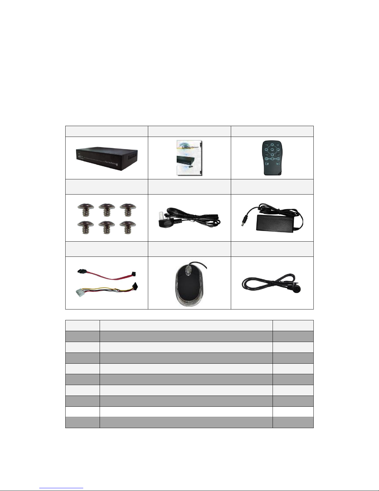
Chapter 1 Unpacking .....................................................................................................3
1.1 Unpacking........................................................................................................3
Chapter 2 Installation.....................................................................................................4
2.1 DVR Overview ................................................................................................4
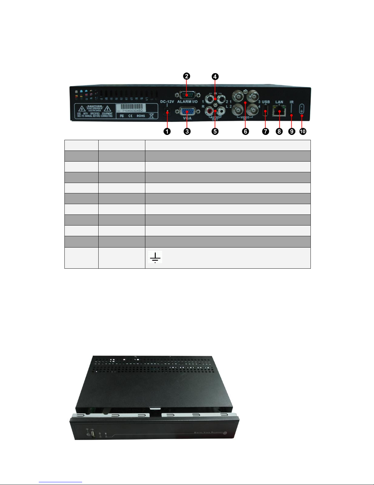
2.2 Rear Panel........................................................................................................5
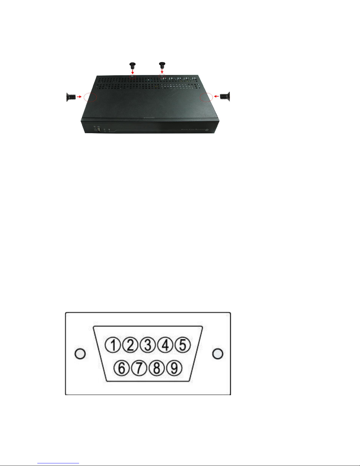
2.3 SATAHDD Installation ...................................................................................5
2.4 Alarm Installation.............................................................................................8
Chapter 3 Getting Start ................................................................................................10
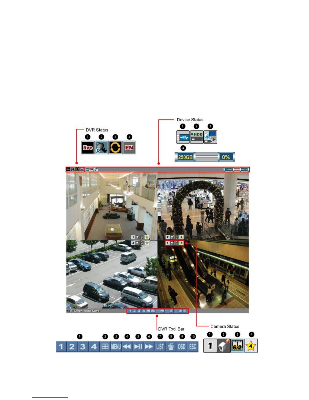
3.1 Start Screen....................................................................................................10
3.2 Full Screen.....................................................................................................13
3.3 Quad Screen...................................................................................................14
3.4 Main Menu.....................................................................................................14
3.5 Event List.......................................................................................................16
3.6 Playback.........................................................................................................18
Chapter 4 Main Menu..................................................................................................22
4.1 Camera...........................................................................................................23
4.2 Setup ..............................................................................................................24
4.3 Record............................................................................................................28
4.4 Alarm..............................................................................................................31
4.5 USB Backup...................................................................................................33
4.6 Network..........................................................................................................38
Chapter 5 Network.......................................................................................................40
5.1 System Requirements.....................................................................................40
5.2 Getting Start...................................................................................................40
Chapter 6 NetView Operation......................................................................................44
6.1 Overview........................................................................................................44
6.2 Live & Playback ............................................................................................45
6.3 Backup ...........................................................................................................47
6.4 Setup ..............................................................................................................53
6.5 PPPoE ............................................................................................................54
6.6 DDNS.............................................................................................................54
Appendix A: Specification...........................................................................................59
Appendix B: FAQ........................................................................................................61

- 3 -
Chapter 1 Unpacking
1.1 Unpacking
1
2
3
4
5
6
7
8
9
Item
Name and description
Pcs
1
DVR
1
2
User guide
1
3
Remote control
1
4
Screws (for HDD fixing)
6
5
Power cord
1
6
Power adaptor (AC 100~240V in, DC 12V out)
1
7
Cables of SATA HDD
2
8
Mouse (optional)
1
9
IR extension cord (optional)
1
NOTE: The type of mouse will be shipped at random.

- 4 -
Chapter 2 Installation
This chapter includes DVR Overview, Rear Panel, SATAHDD & Alarm Installation.
2.1 DVR Overview
Item
Name
Description
1
Front panel
Indicators & USB port
2
Cover
To protect HDD
3
IR receiver
For IR remote control
4
USB port
For USB backup
5
Power indicator
Indicator of power status
6
HDD indicator
Indicator of HDD status

- 5 -
2.2 Rear Panel
Item
Name
Description
1
Power
DC 12V
2
D-SUB 9-pin
For alarm device: Relay, NO, NC
3
VGA
Video output
4
Audio in
RCAx2 (1Vp-p)
5
Audio out
RCA (L, R) (1Vp-p)
6
BNC input
BNC video input x 4
7
USB port
For mouse control
8
LAN
RJ-45
9
IR
IR extension jack
10
GND
GND hole
2.3 SATA HDD Installation
Follow the steps below to install HDD.
Step 1
Lightly push the tongue out; then take the cover away.

- 6 -
Step 2
Plug the cables of HDD properly.
Step 3
Plug the other end of the cables into the HDD.

- 7 -
Step 4
Mind and let the front side of HDD up, and place it in the HDD bay.
Step 5
Fix the HDD by screws (silver).
Step 6
Turn the bottom side of DVR up, fix the HDD by screws (silver).

- 8 -
Step 7
Fix the cover of DVR by screws (black).
NOTE: The HDD will be started 5~30 seconds later after DVR is powered on. If the
HDD is not detected, warning will be showed for 3 seconds by a message “HDD isn’t
installed!”with beep every 10 seconds. User can turn off the buzzer or leave live
mode to quiet down.
NOTE: There are three reasons which may cause the above warning message: 1)
HDD is broken 2) HDD is not installed 3) the recording mode is set as “single-way
recording”and HDD is full.
NOTE: If the HDD is not detected and started within 25 seconds, it will be
determined a failed HDD.
2.4 Alarm Installation
Pin Definition

- 9 -
Pin No
Pin definition
1
Alarm-in 1
2
Alarm-in 2
3
Alarm-in 3
4
Alarm-in 4
5
COM
6
NC
7
NO
8
Do not connect to any cable.
9
GND
Alarm figures
Connect to NO (normal open) or NC (normal close) alarm device:

- 10 -
Chapter 3 Getting Start
In this chapter, it introduces the front panel of DVR, and the definition of icons shown
on event list and live/playback screen.
3.1 Start Screen

- 11 -
DVR Status
1. System Status
Live display
Main menu
Event list
Playback
Pause
Fast forward
Rewind
2. Recording Mode
No recording
Continuing recording
Single-way recording
3. Password level
ID 0 (guest)
ID 1 (normal user)
ID 2 (administrator)
NOTE: The password level will be returned to ID: 0 after 17 seconds without any
operation or pressing twice directly in live screen.
4. Language of OSD
T. Chinese
S. Chinese
Japanese
Czech
Dutch
English
Spanish
French
Italian
German
Polish
Russian
Hebrew
Thai
Danish
Swedish
Finnish
Vietnamese
Device Status
1. USB Flash Drive Status
USB Flash Drive is detected
No USB Flash Drive is detected
2. HDD Status
HDD is installed
HDD is not installed

- 12 -
3. Network Status
Network is working
Network is not working
4. Status Bar of HDD Space
This bar shows the HDD storage & consumption percentage.
The estimate of recording time will be more accurate after at
least one day recording.
DVR Tool Bar
DVR Tool Bar
Switch to full screen display by singly channel
Quad mode
Main menu
Rewind
Playback/pause
Fast forward
Event list
Delete
Show/hide OSD
ESC
Camera Status
1. Channel
Channel 1
Channel 2
Channel 3
Channel 4
2. Recording mode
DVR is recording
Alarm is detected
Alarm recording is on
Motion is detected
Motion recording is on.
NOTE: The red light will be flashed when recording.

- 13 -
3. Frame Rate
NTSC
No
recording
2fps
3fps
5fps
7.5fps
10fps
15fps
PAL
No
recording
1.6fps
2.5fps
4.1fps
6.2fps
8.3fps
12.5fps
4. Image Quality
Basic
Normal
Fine
Good
Excellent
3.2 Full Screen
Left click the mouse on one of the buttons to switch full screen
display in live or playback mode.

- 14 -
3.3 Quad Screen
Left click the mouse on the button to split display in live or playback mode.
3.4 Main Menu
Left click the mouse on the button to call main menu

- 15 -
If users set “Password Enable” as O, the DVR will request at least level 1 (ID: 1)
password to enter Main Menu. Default: ID: 1, Password: 1111 (Refer to Section 4.2
Setup –DVR Password)
Camera
Cameras settings
Setup
To set language, time or
check DVR information
Record
Recording parameters
settings

- 16 -
Alarm
Alarm & motion
settings
USB
backup
For USB backup
function
Network
Network settings
3.5 Event List
Left click the mouse on the button to call main menu

- 17 -
If users set “Password Enable” as O, the DVR will request level 2 (ID: 2) password to
enter Event List. Default: ID: 2, Password: 2222 (Refer to Section 4.2 Setup –DVR
Password).
Each HDD is allowed to save up to 256 events. If users change a new HDD, the event
list will be moved together with the old one.
Left click the mouse on this button to play/pause the event.
Left click the mouse on this button to delete the selected event.
Left click the mouse on this button to go back to the previous page.
Event Filter
Users are able to search events by channels, or event filters.
1. Channels: click the mouse on one of below icons to show specific events by all or
specific channel(s).
All Channels
Channel 1
Channel 2
Channel 3
Channel 4

- 18 -
2. Event Filters: click the mouse on one of below icons to show specific events by
different event filters.
All
Filters
Motion
Video
Loss
Alarm
HDD
ON/OFF
Power
ON/OFF
Mark
USB
The different colors of event filters enable users to search events simply. Meanwhile,
each event filter is come with an auxiliary search cursor in same color, it is helpful to
show users what happened when they are playing the images. (Refer to Section 3.7
Playback).
Event Details
Event No.
Camera
ON/OFF
Filter
Data/Time
Event Source
HDD/USB
In the column of filter, it will show the filter icons in different colors, users can easily
search the events.
When the cursor is moved to one of the events, the background will be changed to the
beginning of the event.
Play Events
Left click the mouse on this button to play/pause the selected event.
3.6 Playback
Operation
In live mode, left click the mouse on the button to enter playback mode.

- 19 -
If users set “Password Enable” as O, the DVR will request at least level 2 (ID: 2)
password to playback mode. Default: ID: 2, Password: 2222 (Refer to Section 4.2
Setup –DVR Password)
Left click the mouse on the numerals
to select date, hour, minute, second or frame and then adjust them by “rolling up or
down”the mouse.
Left click the mouse on this bar to
mark the import timing of video.

- 20 -
NOTE: Channel no. is shown on the left side of the bar.
Switch full screen display of the channel.
Switch quad screen display.
Play/pause the video.
Show event list.
Show/hide OSD.
Exit playback mode.
Playback
In playback mode, left click the mouse on this button to play/pause the video.
Switch full screen display of the channel.
Rewind x 1, 5, 15, 60
Play/pause the video.
Fast forward x 1, 5, 15, 60
Table of contents
Other CCTV DVR manuals