CCTV Odyssey User manual

User Manual

User Manual
CONTENT
Safety Instruction ..........................................................................................................................................................4
Chapter 1 Features............................................................................................................................................................1
Chapter 2: Overview........................................................................................................................................................2
2.1 Front Panel............................................................................................................................................................2
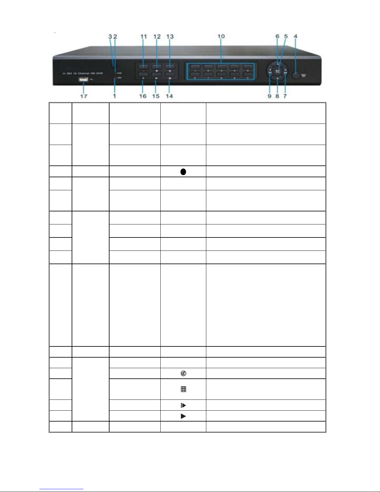
2.1.1、4Channel DVR Front Panel ....................................................................................................................2
2.1.2、8Channel DVR Front Panel ....................................................................................................................3
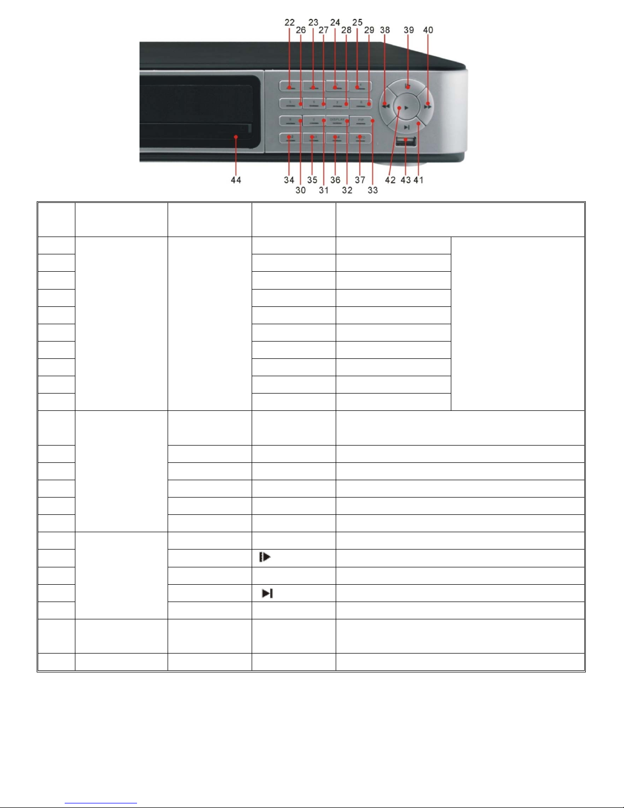
2.1.3、16Channel DVR Front Panel ..................................................................................................................4
2.2 Rear Panel.............................................................................................................................................................9
2.2.1、4Channel DVR Back Panel.....................................................................................................................9
2.2.2、8Channel DVR Back Panel.....................................................................................................................9
2.2.4、16Channel DVR Back Panel.................................................................................................................10
2.3 4/8-CH Remote Controller .................................................................................................................................13
2.4 16-CH Remote Controller...................................................................................................................................14
Chapter 3 DVR INSTALLATION....................................................................................................................................16
3.1 HDD Installation (Applicable to the model with HDD drawer).................................................................16
3.2 Camera and Monitor Connection......................................................................................................................16
3.3 Power Supply connection .................................................................................................................................16
Chapter 4: DVR Boot up ..................................................................................................................................................17
4.1 System Initialization ...........................................................................................................................................17
4.2 Live Interface......................................................................................................................................................17
Chapter 5: DVR Menu......................................................................................................................................................17
5.1 Pop-up Menu ......................................................................................................................................................17
5.2 Main Menu Guide...............................................................................................................................................18
5.3 Main Menu .........................................................................................................................................................19
5.3.1 Display.....................................................................................................................................................19
5.3.2 Record set ................................................................................................................................................21
5.3.3 Search ......................................................................................................................................................23
5.3.4 Network ...................................................................................................................................................27
5.3.5 Alarm .......................................................................................................................................................30
5.3.6 Device......................................................................................................................................................32
5.3.7 System .....................................................................................................................................................34
5.3.8 Advanced .................................................................................................................................................36
5.4 Menu Lock..........................................................................................................................................................37
5.5 Split mode...........................................................................................................................................................37
5.6 PTZ Control........................................................................................................................................................37
5.7 PIP Mode ............................................................................................................................................................38
5.8 Record search......................................................................................................................................................38
5.9 Mute....................................................................................................................................................................39
5.10 Manual Record..................................................................................................................................................39
5.11 Stop record........................................................................................................................................................39
5.12 Start Sequence ..................................................................................................................................................39
5.13 Start Cruise .......................................................................................................................................................39

User Manual
Chapter 6: Web Application Manager .........................................................................................................................40
6.1 Plug-in download and installation ......................................................................................................................40
6.2 Web Application Manager Log-in.......................................................................................................................41
6.3 Live interface......................................................................................................................................................41
6.3.1 Menu Bar .................................................................................................................................................41
6.3.2 Playback...................................................................................................................................................43
6.3.3 Configuration...........................................................................................................................................46
6.3.4 Local setting.............................................................................................................................................55
6.3.5 Logout......................................................................................................................................................55
Chapter 7: Appendix......................................................................................................................................................56
7.1 Operation Function Table ...................................................................................................................................56
7.2 Record Alarm setting ..........................................................................................................................................57
7.3 Mail box server List............................................................................................................................................57
7.4 Troubleshooting ..................................................................................................................................................58
7.5 Usage Maintenance.............................................................................................................................................59
7.6 System Connection Diagram ..............................................................................................................................59
7.7 Accessories .........................................................................................................................................................61

User Manual
Safety Instruction
1. Read Instruction
All the safety and operating instruction should be read before the equipment is operated.
2. Power sources
This equipment should be operated only from the type of power source indicated on the marking label.
If you are not sure of the type of power, please consult your equipment dealer.
3. Objects and Liquid
Never push objects of any kind through openings of this equipment and / or spill liquid of any kind on
the equipment as they may touch dangerous voltage points or short out parts that could result in a fire or
electric shock.
4. Water and / or Moisture
Do not use this equipment near water or in contact with water.
5. Heat sources
Do not install near any heat sources such as radiators, heat registers, stoves or other apparatus
(including amplifier) that produce heat.
6. Dusty field
Never use this equipment near dusty or intense magnetic field.
7. Cleaning
Unplug this equipment from the wall outlet before cleaning it. Do not use liquid aerosol cleaners. Use
a damp soft cloth for cleaning.
8. Lightning
Unplug this equipment during lightning storm or when unused for long periods of time.
9. Accessories
Do not place this equipment on an unstable cart, stand or table. When a cart is used, use caution
when moving the cart / apparatus combination to avoid injury from tip-over.
10.Moving
Disconnect the power before moving the equipment. And the equipment should be moved with care.
11. Attachment
Never add any attachments and/or equipment without the approval of the manufacturer as such
additions may result in the risk of fire, electric shock and other personal injury.
12. Correct Batteries
Risk of explosion occurs if battery is replaced by an incorrect type. Therefore you must use the same
type of battery as the one being used in the product.
13. Ventilation.
Do not block any ventilation openings, installation of the equipment in the rack should be such that
the amount of airflow required for safe operation of the equipment is not compromised.
14. Overloading
Do not overload wall outlets and extension cords to avoid the risk of fire or electric shock.
15. Reliable Earthlings (Grounding)
Reliable grounding of rack mounted equipment should be maintained. Particular attention should be given to
supply connections other than direct connections to the branch circuit.

1
Chapter 1 Features
Function Brief and Description
Real time
monitoring
Double video output; with monitor, VGA virtual output port or HDMI Output;
Support net-viewer and MP live surveillance and also support zoom in/out, auto
sequence and PIP display.
Record
H.264 video compression format; record quality/resolution/frame rate adjustable,
multiple record modes (Always, Scheduled, Manual, Alarm, Motion detection and
remote record)
Record
storage Support SATA large capacity HDD and save real-time record image to HDD.
Playback Support DVR single CH and multiple CH Search/Playback of recorded files.
Backup Support DVR backup via USB flash drive, removable drive, Recorder and
network.
Alarm Setting Supports HDD & video input alarm management and external alarm signal
inputs.
Network
operation Supports remote surveillance by authority users to increase system security.
Mouse
Operation Supports Mouse operation for faster menu navigation.
PTZ Control Supports PTZ camera operations through RS-485.
List 1-1
Features:
H. 264 video compression format; supports D1 resolution;
ADPCM audio compression format
Windows Graphical interface; embedded real-time Linux2.6 operation system;
Friendly Menu reminder;
Multiple operation modes (Preview, record, playback, backup, network surveillance
and mobile phone monitoring);
Supports Double Encode bit network transmission;
Supports remote live surveillance via 3G mobile networks;
Supports Zoom in/out and sequence function;
The video package time is adjustable;
Multiple alarm record modes;
Rear USB2.0 ports for back-up, upgrade and mouse operation;
With IR remote control operation;
Multiple language OSD;
Support auto-maintain.

User Manual
2
Chapter 2: Overview
2.1 Front Panel
Reminder: DVR is the abbreviation of Digital Video Recorder Equipment.
2.1.1 4Channel DVR Front Panel
Item Key title
or Indicator Remark Function & Description
1 USB Port Connect to USB2.0 port
2 Power Indicator PWR If the “Green” indicator is on the system is getting power normally.
3 IR Receiver Receives IR signal from Remote Controller
4 HDD Indicator HDD When the “Red” indicator flashes it means the hard drive is being read or written to.
5 CH select Key:
CH1\CH2\CH3\CH4
CH select key
6 QUAD On Live display or Playback mode, switch to Quad display.
7 REW Left direction key, Rewind key;
Pressing the key to decrease PTZ rotation speed and parameter value.
8 PAUSE Pause / play frame by frame manually
9 PLAY Enter into [Record Search] Menu; Play record file.
10 FWD
Right direction key, Forward key;
Pressing the key to increase PTZ rotation speed and
Parameter value.
11 STOP Stop Playing and/or manual recording.
12 REC ●Start manual record
13 MENU/ESC Enter into Main menu or Exit
14 Up key Move to up
15 SEL/EDIT Enter into pop-up menu; Select or Enter menu;
Edit menu.
16 Down key Move to down
17 PTZ:Enter into pop-up menu.
List 2-1

User Manual
3
2.1.2 8Channel DVR Front Panel
Item Key title or Indicator Remark Function & Description
1 USB Port Connect to USB2.0 port
2 Power Indicator PWR If the “Green” indicator is on the system is getting power
normally.
3 IR Receiver Receives IR signal from Remote Controller
4 HDD Indicator HDD When the “Red” indicator flashes it means the hard drive is
being read or written to.
5 SEARCH Record search
6 MUTE Mute on/off
7 CH- Switch to previous channel
8 CH+ Switch to next channel
9 QUAD On live mode, clicking the button will switch to Quad display.
10 REW
Move to left;
Rewind playing at multiple speeds;
Decrease parameter value of image setting.
11 PAUSE Pause/play frame by frame manually
12 PLAY Enter into pop up menu; Play recording file
13 FWD
Move to right;
Forward playing at multiple speeds;
Increase parameter value of image setting
14 STOP Stop playing; Stop manual record
15 REC ●Start manual record
16 MENU/ESC Enter into Main menu/Exit
17 Up direction key Move to up
18 SEL/EDIT
Enter into pop-up menu;
Confirm the selected operation
Enter into [Edit] function
19 Down direction key Move to down
20 PTZ:Enter into pop up menu.
List 2-2

User Manual
4
2.1.3 16Channel DVR Front Panel
a)
Item Type Key title
/Indicator Marks Function
1 HDD indicator HDD When the “Red” indicator flashes it means the
hard drive is being read or written to.
2
Indicator
Power indicator PWR If the “Green” indicator is on the system is
getting power normally.
3 IR Receiver Receives IR signal from Remote Control
4 Menu MENU/ESC
Enter into main menu / Exit
5
Complex
Key PTZ PTZ Enter into PTZ control, select [Enter] / [Edit]
operation
6 UP Move up
7 RIGHT /Move right / FWD
8 DOWN Move down
9
Direction
Key
LEFT /Move left / RWD
10
Channel
Select &
numeric
input
Single Channel
and numeric key
Numeric key
0,1-9 and CH
key CH1~9
1. Number 1~9 stand for numeric 1~9 and
CH 1~9.
2. CH11-CH16 select method: press firstly
numeric key 1 and then other numeric
key. For example CH16 select firstly
press 1, and then press 6.
3. Holding press key 0 for three seconds
may convert current output device
11 Rec. Manual record ●Press the button to start manual record.
12 Stop Stop playing and stop manual record
13 Mute Open or close audio input
14 Multi Display Live display Quad mode, 9-split and 16-split
mode
15 By frame Play frame by frame
16
Play
Control
Play Convert to play status
17 USB Port Connect to USB2.0 port
List 2-3

User Manual
5
b)
Item Type Key title
/Indicator Marks Function
1 Left arrow key Move left
2 Up arrow key Move up
3 Right arrow key Move right
4
Direction Key
Down arrow key Move down
5 Enter key ENTER
Press the [Enter] key to enter into PTZ control, confirm the processing or
start editing.
6
Complex Key
Menu key MENU/ESC Press the [Menu] key to enter into or exit Main menu.
7 Manual Record key REC Press the key to activate manual record function.
8 Record Stop key STOP Press the key the stop record.
9 Audio Control Mute key MUTE Press the key to open or close audio input/output.
10 Search Search key SEAR Press the key to start record search.
11 PTZ Control PTZ key PTZ Allow you set preset point or proceed PTZ control.
12 Zoom in Z+ key Z+ Press the key to zoom in live monitoring area.
13 Focus F+ key F+ Press the key to extend focus close
14 Iris I+ key I+
Press the key to increase the brightness of camera with PTZ control.
15 Lock Lock key LOCK Press the key to lock system.
16 Zoom out Z- key Z- Press the key to zoom out live monitoring area.
17 Focus F- key F- Press the key to extend focus far.
18 Iris I- key I-
Press the key to decrease the brightness of camera with PTZ control
19 IR Receiver Receive IR signal remotely.
20 PWR Indicator POWER If the indicator is in green the system is getting power normally.
21 Rec. Indicator REC If the indicator flashes in red, that means the DVR is recording.
List 2-4

User Manual
6
Item Type Key title
/Indicator Marks Function
22 1 CH1;Numeric key1
23 2 CH2;Numeric key2
24 3 CH3;Numeric key3
25 4 CH4;Numeric key4
26 5 CH5;Numeric key5
27 6 CH6;Numeric key6
28 7 CH7;Numeric key7
29 8 CH8;Numeric key8
30 9 CH9;Numeric key9
31
Channel Display
Numeric Input
CH select and
Numeric key
0
CH11-CH16 select method:
press key 1 plus other
numeric key. Such as CH16
display, firstly press 1, then
press 6.
32 Multiple display
Mode
DISPLAY Multiple display modes include 4-split mode, 9-split
mode, 16-split mode and full screen display
33 PIP mode PIP IP display mode
34 2x2 key 2×2 Quad display mode
35 3X3 key 3×3 9-split mode
36 4X4 key 4×4 16-split mode
37
Display mode
Auto key AUTO Dwell time display
38 REW key Rewind (X2、X4、X8)
39 Pause key Pause / play frame by frame
40 FWD key Forward (X2、X4、X8)
41 Slow Play key Manual Slow Play
42
Play Control
Play key Switch to Play mode
43 USB Port Connect USB device (Flash Drive, Hard Drive and
Recorder etc)
44 DVD-Control Push Key Control DVD-RW output and inside
List 2-5

User Manual
7
c)

User Manual
8
List 2-6
NO. Key title Marks Function
1 Shuttle
button
On the menu mode, rotate the outside circle to right-and-left move
menu setting items and rotate the inner circle to up-and-down move
the menu setting items.
2 USB Port Left: Port for Mouse; Right: Port for storage device.
3 Up/Down
direction
ke
y
S、TAllow you change numbers and settings etc. in edit boxes or pull-down
menu
4 Left/Right
direction
ke
y
W、XOn the main/sub-menu mode, allow you move curse freely; on the
playback mode, allow you toggle with different function keys.
5 Enter Enter into main menu and select [Enter] operation
6 IR
Receiver Receive IR signal from Remote Control
7 Numeric
Keys 0-16 Number input / Channel switch
8 RW Key On the playback mode, clicking the key allow you rewind the record at
multiple speeds.
9 Slow key f│On the playback mode, clicking the key allows you play the record
manually frame by frame.
10 Play key ►Clicking the key allows you switch to play mode.
11 Sto
p
ke
y
│
►Clickin
g
the ke
y
allows
y
ou
p
asue/
p
la
y
the record
y
ou selected.
12 FF Key On the playback mode, clicking the key allow you forward the record at
multiple speeds.。
13
Display
mode
DISPL
AY
On live mode, clicking the key allows you enter into Quad
mode,9-split mode and 16-split mode (Remark: Hold clicking the
[Display] key for three seconds to convert current output.
14 PIP Ke
y
PIP Allow
y
ou enter into PIP mode.
15 Search ke
y
SEAR Allow
y
ou search the recordin
g
file
16 Sto
p
ke
y
STOP Allow
y
ou sto
p
the current record.
17 Rec ke
y
●REC Allow
y
ou manuall
y
record the ima
g
es.
18 PWR Power on/off(holdin
g
to click the ke
y
for three seconds to close the device.)
19 Mute ke
y
MUTE Allow
y
ou o
p
en or close the audio
20 PTZ PTZ Allow
y
ou enter into PTZ interface.
21 ESC Ke
y
ESC Exit the
p
revious menu or cancel the menu command.
22 Menu MENU On the dis
p
la
y
mode, click the
[
menu
]
ke
y
to
p
o
p
u
p
the main menu.
23 Recorde
r
CD/DVD recorder
(
O
p
tional
)
PWR Power indicator
HDD HDD indicator
READ Run indicator
STAT Status indicator
RECO Recorder indicator
BACK Backup indicator
ALAR Alarm indicator
24 Indicator
LINK Net indicator

User Manual
9
2.2 Rear Panel
2.2.1 4 Channel DVR Rear Panel
2.2.2 8 Channel DVR Rear Panel
a)
Item Physical port Connection method
1 Video input 4CH:Connect CH1-4 (Virtual) video input device(BNC interface)
8CH:Connect CH1-8 (Virtual) video input device(BNC interface)
2 Video output Connect monitor output (BNC interface)
3 Audio Input 4CH DVR: 4CH audio input (BNC interface)
8CH DVR: 4CH audio input (BNC interface)
4 Audio Output 4CH DVR: 2CH output; BNC (interface)
8CH DVR:2CH output. BNC (interface)
5 Ethernet: Port Connect LAN, Ethernet (RJ45 interface)
6 VGA Port Connect to VGA monitor, such as PC monitor (Optional)
7 USB Port Connect USB mouse
8 USB Port Connect USB device (Flash Drive, Hard Drive and Recorder etc)
9 RS-485 RS485 interface
10 Power Port Connect power supply - DC12V 3A/5A
List 2-7

User Manual
10
2.2.2 b)
Item Physical port Connection method
1 Video input 8CH:Connect CH1-8 (Virtual) video input device(BNC interface)
2 Video output Connect monitor output (BNC interface)
3 Audio Output 8CH DVR:8CH output. BNC (interface)
4 Ethernet: Port Connect LAN, Ethernet (RJ45 interface)
5 VGA Port Connect to VGA monitor, such as PC monitor (Optional)
6 USB Port Connect USB mouse
7 ALARM RS-485 / Sensor / Alarm
8 Power Port Connect power supply - DC12V 3A
9 Power Switch Turn Power on and off
List 2-8
2.2.3 16 Channel DVR Rear Panel
a)
Item Physical port Connection method
1 Video input Connect CH1-16 (Virtual) video input(BNC interface)
2 Video output Connect monitor output(BNC interface)
3 Audio input Connect CH1-4 audio signal input (BNC interface)
4 Audio output 2CH output; BNC (interface)
5 Ethernet: Port Connect LAN, Ethernet (RJ45 interface)
6 Power Switch Turn Power on and off
7 HDMI HDMI Output
8 VGA Port Connect to VGA monitor, such as PC monitor
9 USB Port Connect USB mouse
10 RS-485/Sensor/Alarm RS485/Sensor/Alarm interface (see pin outs below)
11 Power Port Connect power supply - DC12V 5A
List 2-9

User Manual
11
b)
Item Physical port Connection method
1 Video input Connect CH1-16 (Virtual) video input(BNC interface)
2 Video output (UP) Main video output; (Down) Spot output (BNC interface)
3 Audio input Connect CH1-4 audio signal input (BNC interface)
4 Audio output Connect audio signal output, including spot main audio output
and sequence audio output (BNC interface)
5 Audio input Connect (CH5~CH16) Audio input
6 Ethernet: Port Connect LAN, Ethernet (RJ45 interface)
7 Power Switch Turn Power on and off
8 VGA Port Connect to VGA monitor, such as PC monitor
9 USB Port Connect USB mouse
10 RS-485/Sensor/Alarm RS485/Sensor/Alarm interface (see pin outs below)
11 Power Port Connect power supply - DC12V 5A
c) List 2-10
Item Physical port Connection method
1 Video input Connect CH1-16 (Virtual) video input(BNC interface)
2 Audio input Connect CH1-4 audio signal input (BNC interface)
3 Video output (UP) Main video output; (Down) Spot output (BNC interface)
4 Audio output Connect audio signal output, including spot main audio output
and sequence audio output (BNC interface)
5 Audio input Connect (CH5~CH16) Audio input
6 HDMI HDMI Output
7 Ethernet: Port Connect LAN, Ethernet (RJ45 interface)
8 RS-232 Undefined
9 VGA Port Connect to VGA monitor, such as PC monitor
10 RS-485/Sensor/Alarm RS485/Sensor/Alarm interface (see pin outs below)
11 Power Port Power Supply

User Manual
12
List 2-11
RS485/Sensor/Alarm port functions:
Alarm input: Connect [-] port of your sensor to G (GND) pin, and [+] port to channel input
according to the alarm device you purchased.
Alarm output: Connect to the two ports marked with “out”
PTZ Port:Connect your camera to RS-485A and RS485B accordingly.

User Manual
13
2.3 4/8-CH Remote Controller
Item Key title Key function
1 1-8 Channel select 1-8; Numeric key
2
9、0
Numeric key; Clicking numeric “0” allow you
switch to GUI (Graphical user Interface)
function
3 ALL Multiple display mode
4 Menu Enter into Main menu/Exit
5 ▲Up arrow key, Volume adjust
6 ▼Down arrow key, Volume adjust
7
◄/
Left/Down key,
Decrease/increase parameter value of
control bar
8 SEL Select key/Edit key;
Confirm the selected operation.
9 Rewind key
10 Enter into record search menu;
Play key
11 Forward key
12 ●Record key
13 Pause/Sequence key
14 ■Stop manual record; stop playing
15 Audio Testing
16 Mute Mute on/off

User Manual
14
2.4 16-CH Remote Controller
Key Title Key Function
REC Press the button to enter into manual record.
SEARCH Press the button to enter into record search menu
2×2 Enter into Quad display
3×3 Enter into 9-split display
4×4 Enter into 16-split display
AUTO Enter into dwell time display
0~9 Channel select; numeric key
DISPLAY
MODE
Multiple CH display (Quad, 9-split, 16-split and full
screen display)
▲Up direction key
▼Down direction key
◄/Left/right direction key; also decrease/increase
parameter value of control bar.
ENTER select [Enter] / [Edit] operation
Menu/ESC Enter into/exit Main menu
PIP PIP display mode
MUTE Mute key
FWD Forward(x2、x4、x8)
REW Rewind(x2、x4、x8)
PLAY Enter into record search, play record event
STOP Stop play / manual play
PAUSE/
FRAME Pause / play frame by frame
SLOW (1/2、1/4、1/8)Slow play
Z+ Zoom out video area
Z- Zoom in video area
F+ Extend focus
F- Extend focus
I+ Increase PTZ brightness
I- Decrease PTZ brightness
PTZ Allow you set preset bit and control PTZ.
LOCK Lock system

User Manual
15
Mouse Operation
Except using buttons of front panel or remote controller, you also can use mouse to
perform system operation.
TYPE Function
In menu lock mode, Enter into pop-up menu and clicking any sub menu to
pop up Log-in window; on menu unlock mode, enter into pop-up menu, and
then clicking left key to enter into any sub menu directly.
After entering into main menu, clicking left key could enter into any sub
menu; On [Detailed file] menu mode, clicking left key could playback one
recording file.
Change the status of check box and motion detection area.
Clicking combo box to access pull-down menu; Click left key to stop dwell
time display when dwell time display is activated.
By clicking left key you can adjust Color control bar and volume control
bar.
Clicking combo box to access pull-down menu
Click left key of
Mouse
By clicking left key you can select values in edit boxes or pull-down menu
and supports Chinese word input, special symbol, numeric and character input,
use instead of [Enter- ] or [Backspace ]
In live display mode, clicking right key will display pop-up menu (shown
as Picture 5-1).
Click right
key of Mouse In Main menu or sub menu mode, clicking right key will exit current menu.
Double-click Left
key of Mouse
In live display or playback mode, double-clicking left key will maximize
the screen.
Moving Mouse Select menu item
Sliding Mouse On motion mode, sliding mouse will select motion area; On [Color set]
menu mode, sliding mouse will adjust color control bar and volume control bar.

User Manual
16
Chapter 3 DVR INSTALLATION
3.1 HDD Installation (Applicable to the model with HDD drawer)
Caution:Please do not Install or take out hard drive when DVR is running!
(1) The model has a HDD drawer. Please use provided key to take out the HDD
drawer and put HDD into the drawer correctly.
(2) Cut power firstly, and then remove screws and open DVR upper cover carefully;
(3) Insert Power Cord and data cable into Pin of hard drive securely;
(4) Remove the screws on the HDD bracket; fix the HDD to the bracket and then fix
the bracket with HDD to DVR body
(5) Put the upper cover back carefully, re-attach screws.
Note: If user requires higher performance HDD, strongly recommend you use special
hard driver for security and protection
3.2 Camera and Monitor Connection
Connect camera cable to video input of DVR, and from video output of DVR to
Monitor via BNC connector (Refer to section2.2-Rear Panel); or
If the camera is a PTZ speed dome, you could connect RS485 A & B to the according
port of DVR respectively (refer to system figuration on Chapter 8).
3.3 Power Supply connection
Please only use the power adapter supplied with the DVR.
After power on please make sure the video I/O connection well, audio device with
RCA cable.
Table of contents
Other CCTV DVR manuals
Popular DVR manuals by other brands

Endura
Endura DVR5100 Series Specifications

American Dynamics
American Dynamics Intellex Intellex Ultra user guide

Digital Watchdog
Digital Watchdog DW-VAC42T quick start guide

COP-USA
COP-USA DVR2708TE-TVI user manual

Digital Watchdog
Digital Watchdog VMAX A1 Plus DW-VA1P41T quick start guide

VDigi
VDigi VD-i user manual