CEAG COOPER 71011 (CG-S) User manual

Betriebsanleitung
Alu-Klick Rettungszeichen-
und Sicherheitsleuchten
Zielgruppe: Elektrofachkräfte
Operating Instructions
Alu-Klick exit and escape luminaires
Target group: Skilled electricians
SL/RZ 70011 (CG-S); RZ 70021 (CG-S)
SL/RZ 71011 (CG-S); RZ 71021 (CG-S)
RZ 71011 (CG-S) IP 54; --
SL/RZ 72011 CG-S; RZ 72021 CG-S
SL/RZ 79011 CG-S; RZ 79021 CG-S
400 71 351 470 (B)

CEAG Notlichtsysteme GmbH 2
Montage- und Betriebsanleitung
Rettungszeichen- und Sicherheitsleuchten
Alu-Klick 70011...79011 (CG-S)
Inhaltsverzeichnis / Table of contents
11
11
1Aufbau der Leuchte / Construction of the luminaireAufbau der Leuchte / Construction of the luminaire
Aufbau der Leuchte / Construction of the luminaireAufbau der Leuchte / Construction of the luminaire
Aufbau der Leuchte / Construction of the luminaire ................................
................................
................ 33
33
3
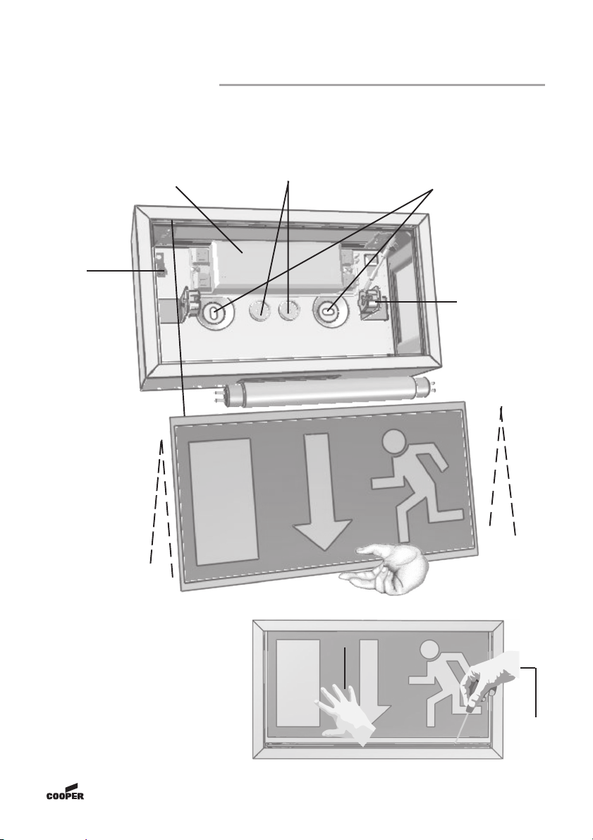
1.1 SL/RZ 70011...79011 ....................................................................................................... 3
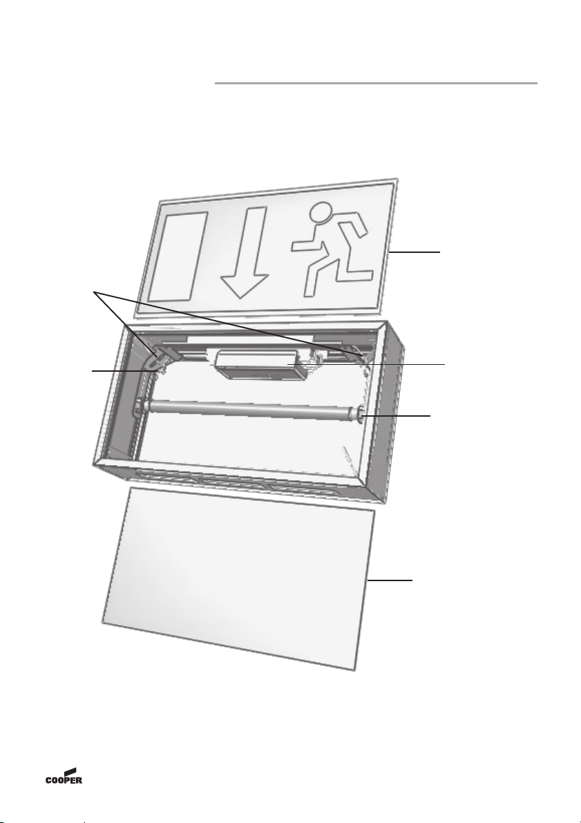
1.2 RZ 70021...79021 (CG-S) ................................................................................................. 4
1.3 SL / RZ 71011 (CG-S) IP 54 ............................................................................................. 5
22
22
2Maßbilder / Dimensional DrawingsMaßbilder / Dimensional Drawings
Maßbilder / Dimensional DrawingsMaßbilder / Dimensional Drawings
Maßbilder / Dimensional Drawings ..........................................................................................
..........................................................................................
............................................. 66
66
6
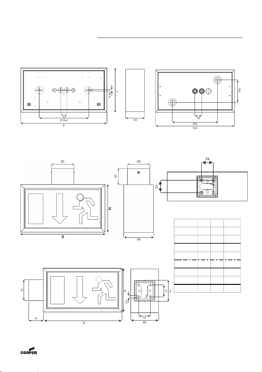
2.1 70011...79011 (CG-S) Decken-, o. Wandmontage / Ceiling or wall mounting ............... 6
2.2 RZ 71011(CG-S) IP54 nur Wandmontage / Only wall mounting ..................................... 6
2.3 70021...72021 (CG-S) Deckenmontage / Ceiling mounting ............................................ 6
2.4 70021...72021 (CG-S) Wandmontage / Wall mounting ................................................... 6
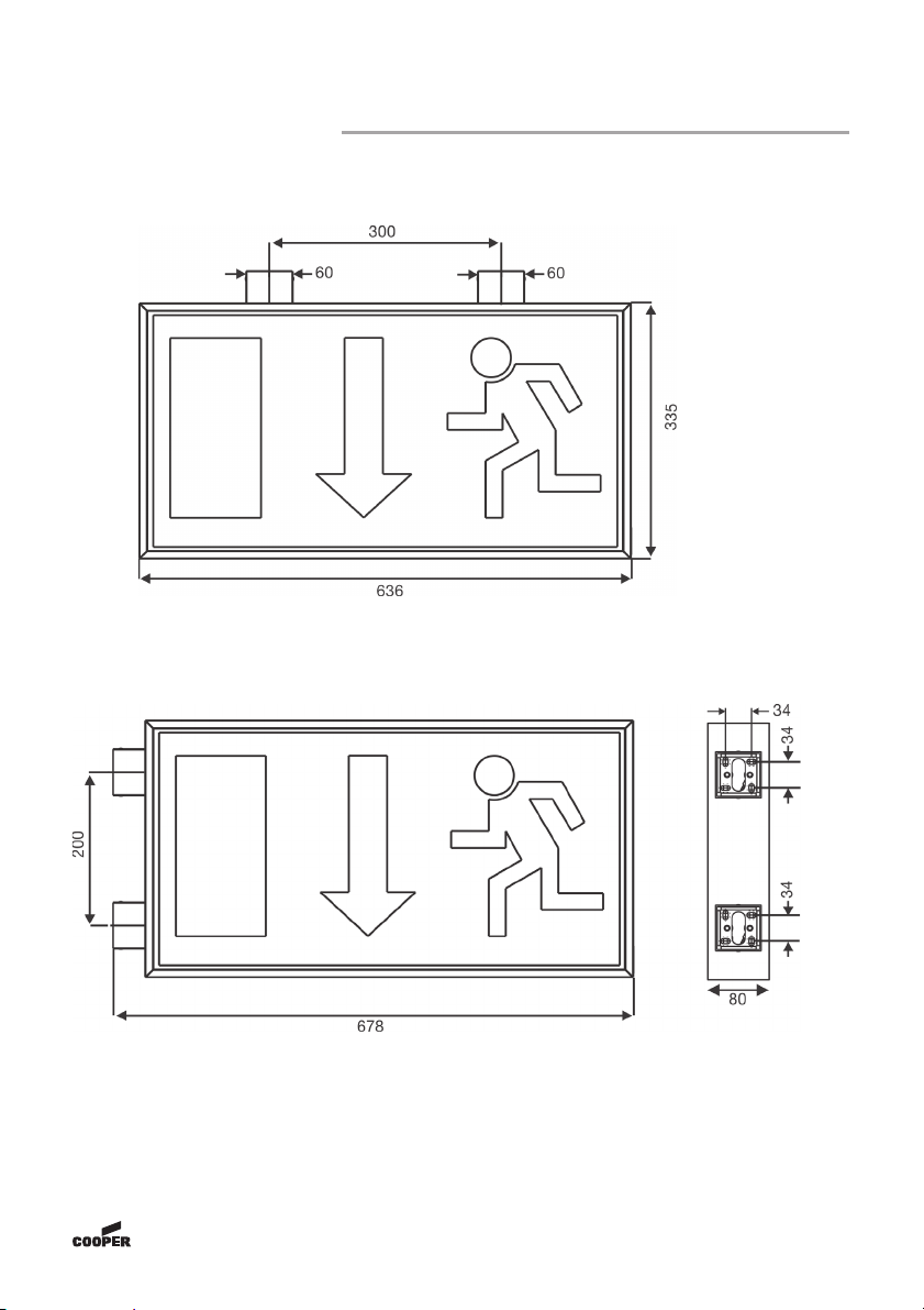
2.5 79021 (CG-S) Deckenmontage / Ceiling mounting .......................................................... 7
2.6 79021 (CG-S) Wandmontage / Wall mounting ................................................................. 7
2.7 Einzelpendel 0,5m / Single Pendulum 0,5m für / for 70021 (CG-S) ............................... 8
2.9 Pendelmontage / Pendulum Mounting Set für / for 72021...79021 (CG-S) .................... 8
2.8 Pendel Set 0,5m / Pendulum Set 0,5m für / for 72021...79021 (CG-S) .......................... 8
33
33
3SicherheitshinweiseSicherheitshinweise
SicherheitshinweiseSicherheitshinweise
Sicherheitshinweise ..............................................................................................................................................
..............................................................................................................................................
....................................................................... 99
99
9
44
44
4NormenkonformitätNormenkonformität
NormenkonformitätNormenkonformität
Normenkonformität ..................................................................................................................................................
..................................................................................................................................................
......................................................................... 99
99
9
55
55
5TT
TT
Technische Datenechnische Daten
echnische Datenechnische Daten
echnische Daten ......................................................................................................................................................
......................................................................................................................................................
........................................................................... 99
99
9
5.1 Verwendungsbereich / Kurzbeschreibung ..................................................................... 9
66
66
6Installation / InbetriebnahmeInstallation / Inbetriebnahme
Installation / InbetriebnahmeInstallation / Inbetriebnahme
Installation / Inbetriebnahme ..........................................................................................................
..........................................................................................................
..................................................... 1010
1010
10
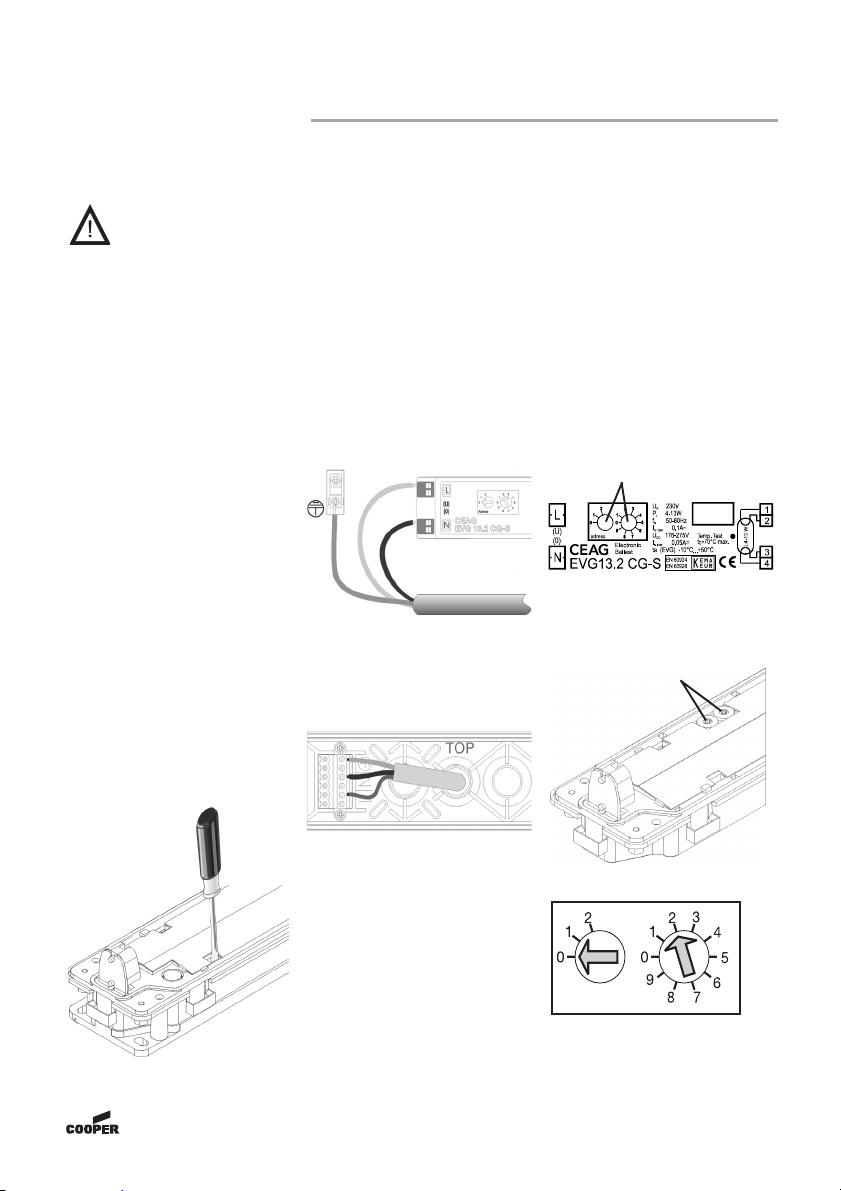
6.1 Montage .......................................................................................................................... 10
6.2 Adressierung .................................................................................................................. 10
6.3 Montagezubehör (s. Abb. 6 - Abb. 12) ......................................................................... 11
77
77
7Wartung / InstandhaltungWartung / Instandhaltung
Wartung / InstandhaltungWartung / Instandhaltung
Wartung / Instandhaltung ........................................................................................................................
........................................................................................................................
............................................................ 1111
1111
11
88
88
8Entsorgung / RecyclingEntsorgung / Recycling
Entsorgung / RecyclingEntsorgung / Recycling
Entsorgung / Recycling ..............................................................................................................................
..............................................................................................................................
............................................................... 1111
1111
11
33
33
3Safety instructionsSafety instructions
Safety instructionsSafety instructions
Safety instructions ..............................................................................................................................................
..............................................................................................................................................
....................................................................... 1212
1212
12
44
44
4Conformity with standardsConformity with standards
Conformity with standardsConformity with standards
Conformity with standards ..................................................................................................................
..................................................................................................................
......................................................... 1212
1212
12
55
55
5TT
TT
Technical dataechnical data
echnical dataechnical data
echnical data ............................................................................................................................................................
............................................................................................................................................................
.............................................................................. 1212
1212
12
5.1 Brief description / Scope of application ........................................................................ 12
66
66
6InstallationInstallation
InstallationInstallation
Installation..........................................................................................................................................................................
..........................................................................................................................................................................
..................................................................................... 1313
1313
13
6.1 Mounting ......................................................................................................................... 13
6.2 Addressing ..................................................................................................................... 13
6.3 Mounting accessories (see fig. 6 - 12) .......................................................................... 14
77
77
7ServicingServicing
ServicingServicing
Servicing ................................................................................................................................................................................
................................................................................................................................................................................
........................................................................................ 1515
1515
15
88
88
8RecyclingRecycling
RecyclingRecycling
Recycling ..............................................................................................................................................................................
..............................................................................................................................................................................
....................................................................................... 1515
1515
15

CEAG Notlichtsysteme GmbH 3
Montage- und Betriebsanleitung
Rettungszeichen- und Sicherheitsleuchten
Alu-Klick 70011...79011 (CG-S)
Öffnen:
Piktogrammscheibe nach
oben schieben (1) und unten
aus dem Rahmen heben, evtl.
mit Hilfe eines breiten
Schraubendrehers (2).
To open:
Push cover upwards and take out of
enclosure (1) - perhaps with the aid of a flat
screwdriver (2)
Befestigungslöcher
fixing holes
W
W
Schließen:
Piktogrammschei-
be nach oben
schieben und
unten einrasten
lassen.
To close:
Push cover upwards and
snap into enclosure
Leitungseinführungen
cable entries
EVG
electronic balast
PE
Anschluss
PE
connection
W
W
Lampenfassung
lamp socket
1
1 Aufbau der Leuchte / Construction of the luminaire
1.1 SL/RZ 70011...79011
Abb. 1
Abb. 2
W
1
2
2
W
W

CEAG Notlichtsysteme GmbH 4
Montage- und Betriebsanleitung
Rettungszeichen- und Sicherheitsleuchten
Alu-Klick 70011...79011 (CG-S)
1.2 RZ 70021...79021 (CG-S)
Piktogramm-
scheibe / cover
EVG /
electronic balast
Lampenfassung /
lamp socket
PE - Anschluss /
PE - connection
Beispiel: Blindscheibe
example: clear cover
Montage der zweiseitigen Leuchte entnehmen Sie bitte dem individuellen Montageset.
For mounting the luminaire, please see the individual mounting accessory - set.
Modulträger lösen,
um Deckenbefesti-
gung zu installie-
ren/
loose module
carrier for ceiling
mounting

CEAG Notlichtsysteme GmbH 5
Montage- und Betriebsanleitung
Rettungszeichen- und Sicherheitsleuchten
Alu-Klick 70011...79011 (CG-S)
1.3 SL / RZ 71011 (CG-S) IP 54
Hinweis:
Bei der Leuchte SL/RZ 71011 (CG-S) IP 54 handelt es sich um ein Leuchtengehäuse
in IP 40, bei der Elektronik und Leuchtmittel in IP 54 geschützt sind.
Note:
Concerning the luminaire SL/RZ 71011 (CG-S) IP 54 it is about an enclosure with IP
40, the electronic and luminaire does fullfill IP 54.
Leuchtenkörper
Body of luminaire
Befestigungslöcher
fixing holes
Klemmblock
terminal block
Leitungseinführungen
cable entries
IP 54 - Abdeckhaube
IP 54 bowl
Abb. 3

CEAG Notlichtsysteme GmbH 6
Montage- und Betriebsanleitung
Rettungszeichen- und Sicherheitsleuchten
Alu-Klick 70011...79011 (CG-S)
2 Maßbilder / Dimensional Drawings
2.3 70021...72021 (CG-S) Deckenmontage / Ceiling mounting
2.4 70021...72021 (CG-S) Wandmontage / wall mounting
Abb. 4
Abb. 5
Abb. 6
Abb. 7
Deckenmontage nur für SL - Ausführung /
Ceiling mounting only for SL version
2.1 70011...79011 (CG-S) Decken-, o. Wand- 2.2 RZ 71011(CG-S) IP54 nur Wand-
montage / Ceiling or wall mounting montage / only wall mounting
(*) = s. Zubehör in Pkt. 6.3 / see 6.3, accessories
(*) (*)
(*)
L. typ B H B Bef.
70011 226 125 100
70021 226 125
71011 349 188 200
71021 349 188
7 10 11 I P 5 4 350 188 200
72011 431 230 200
72021 431 230
79011 636 335 300

CEAG Notlichtsysteme GmbH 7
Montage- und Betriebsanleitung
Rettungszeichen- und Sicherheitsleuchten
Alu-Klick 70011...79011 (CG-S)
2.5 79021 (CG-S) Deckenmontage / Ceiling mounting
2.6 79021 (CG-S) Wandmontage / Wall mounting
Abb. 8
Abb. 9
(*)
(*)
(*)
(*)
(*) = s. Zubehör in Pkt. 6.3 / see 6.3, accessories

CEAG Notlichtsysteme GmbH 8
Montage- und Betriebsanleitung
Rettungszeichen- und Sicherheitsleuchten
Alu-Klick 70011...79011 (CG-S)
2.7 Einzelpendel 0,5m / Single Pendu-
lum 0,5m für / for 70021 (CG-S)
Klemmblock
zum Anschluss
im Baldachin /
terminal block for
connection in the
canopy
W
Leuchte 71021 72021 79021
H690 730 835
2.8 Pendel Set 0,5m / Pendulum Set 0,5m
für / for 72021...79021 (CG-S)
2.9 Pendelmontage / Pendulum Mounting Set für / for
72021...79021 (CG-S)
Abb. 10
Abb. 11
Leitungseinfüh-
rungen / cable entries
Befestigungslöcher / fixing holes
Abb. 12
(*) (*)
(*) = s. Zubehör in Pkt. 6.3 / see 6.3, accessories

CEAG Notlichtsysteme GmbH 9
Montage- und Betriebsanleitung
Rettungszeichen- und Sicherheitsleuchten
Alu-Klick 70011...79011 (CG-S)
3 Sicherheits-
hinweise
Die Leuchte ist bestim-
mungsgemäß in unbeschä-
digtem und einwandfreiem
Zustand zu betreiben!
Als Ersatz dürfen nu
r
Originalteile von CEAG ver-
wendet werden!
Bei Durchführung von Ar-
beiten an der Notleuchte si-
cherstellen, dass die Not-
leuchte spannungsfrei ge-
schaltet ist! Beachten Sie
dabei die unterschiedlichen
Versorgungen der Not-
leuchte bei Normal-, und
Notbetrieb. Bild 13 zeigt das
Hinweisschild auf der Not-
leuchte.
Kennzeichnen Sie die Not-
leuchten: Stromkreis und
Leuchtennummer zuordnen
und eintragen.
Die Protokollführung ist ge-
mäß den nationalen Vor-
schriften durchzuführen
(entfällt bei automatische
r
Protokollierung)!
Vor der ersten Inbetriebnah-
me alle Fremdkörper aus
dem Gerät entfernen!
Beachten Sie bei allen Ar-
beiten an dem Gerät die na-
tionalen Sicherheits-, und
Unfallverhütungsvorschrif-
ten und die nachfolgenden
Sicherheitshinweise in de
r
Betriebsanleitung, die mit
einem versehen sind!
Abb. 13
4 Normen-
konformität
Konform mit: EN 60 598-1,
EN 60 598-2-22, EN1838.
Niederspannungsrichtlinie
93/68/EWG
EMV-Richtlinie
2004/108/EG.
Trotz CE - Konformi-
tät kann eine gegen-
seitige Beeinflus-
sung von Geräten
und Leuchten auf-
treten.
Gemäß DIN EN ISO 9001
entwickelt, gefertigt und ge-
prüft.
5 Technische
Daten
Gehäusemat.: Aluminium
Bei den zweiseitigen Leuch-
ten ist jede Montageart mit
dem jeweiligen Zubehör
möglich, s. Pkt. 6.3.
Gewichte (inkl. Scheiben):
SL/RZ 70011 1,15kg
RZ 70021 1,10kg
SL/RZ 71011 1,65kg
RZ 71011 IP 54 1,95kg
RZ 71021 1,30kg
SL/RZ 72011 2,10kg
RZ 72021 1,60kg
SL/RZ 79011 3,55kg
RZ 79021 3,00kg
Netzanschlussklemmen:
Doppelbelegungsklemmen
3x2,5mm²
Spannungsbereiche:
230V 50/60Hz,
220V DC
+25%/-20%
Stromaufnahme
Batteriebetrieb:
70011...70021 20mA
71011...72021 30mA
79011...79021 70mA
Netzanschlussleistung
70011...70021 10VA
71011...72021 16VA
79011...79021 32,2VA
Zulässiger
Temperaturbereich:
-10°C..+40°C
Leuchtmittel:
70011...70021 4W/T16
140lm
71011...72021 8W/T16,
450lm
79011...79021 18W/T26
18 W nicht im Lieferumfang
enthalten.
Lichtfarbe: „cool-white“ 840
Bemessungs-(DC)
lichtstrom: 75% (AC)
Schutzklasse:
70011...79021 I
71011 IP54 II
Schutzart nach EN 60529:
70011...79021 IP40
71011 IP54 *IP54
(* nur Elektronik u. Leuchtmittel)
5.1 Verwendungsbereich/
Kurzbeschreibung
Rettungszeichen-, und Si-
cherheitsleuchten Alu-Klick
sind für den Betrieb an
CEAG Sicherheitsbeleuch-
tungsanlagen geeignet. Die
besondere Schaltungsart
der CG-S Technologie (Be-
reitschaftslicht, Dauerlicht o.
geschaltetes Dauerlicht) in
einem Stromkreis ist nur an
geeigneten CEAG Sicher-
heitsbeleuchtungsanlagen
einsetzbar.

CEAG Notlichtsysteme GmbH 10
Montage- und Betriebsanleitung
Rettungszeichen- und Sicherheitsleuchten
Alu-Klick 70011...79011 (CG-S)
6 Installation / In-
betriebnahme
Halten Sie die für das
Errichten und Betrei-
ben von elektrischen
Betriebsmitteln gel-
tenden Sicherheits-
vorschriften sowie
die allgemein aner-
kannten Regeln der
Technik ein!
6.1 Montage
- Piktogrammscheibe ent-
fernen (s. hierzu Abb. 2).
Bei Leuchte RZ 71011 (CG-
S) IP 54:
Die IP 54 - Abdeckhaube mit
Hilfe eines Schrauben-
drehers öffnen und entfer-
nen.
Den Leuchtenkörper entfer-
nen (s. Abb. 14 unten).
- Netzleitung einführen.
- Gehäuse an Befestigungs-
löchern mit 2 Schrauben und
2 Dübeln an die Decke /
Wand montieren.
Bei Pendel-, und Ketten-
befestigung werden diese lt.
Zubehörset am Äußeren des
Gehäuses befestigt (ohne
IP54).
- Netzverbindung L(U), N(O),
PE herstellen
(s. Abb. 15, unten).
Bei Leuchte RZ 71011 (CG-
S) IP 54
(Abb. 16, s. unten):
CG-S Leuchte adressieren
(s. Kap. 6.2).
- Leuchtmittel (bei IP 54 vor-
ab zusätzlich Leuchtenkör-
per) einsetzen.
- Scheibe einsetzen (s. Abb.
1).
6.2 Adressierung
Vor Montage der Scheibe
muß die individuelle
Leuchtenadressierung Ihrer
Leuchte mit CG-S - Funkti-
on an den Adressschaltern 1
und 2 eingestellt werden.
Verwenden Sie einen geeig-
neten Schraubendreher
(Pfeil auf Zahl, s. Abb. 17-
19). Soll die Leuchte nicht
überwacht werden, ist immer
die Stellung 0/0 einzustel-
len.
Bei 71011 CG-S IP54
Abb. 19
Abb. 17
Adressschalter
Adressschalter
Abb. 18

CEAG Notlichtsysteme GmbH 11
Montage- und Betriebsanleitung
Rettungszeichen- und Sicherheitsleuchten
Alu-Klick 70011...79011 (CG-S)
7 Wartung /
Instandhaltung
Halten Sie die für Instand-
haltung, Wartung und Prü-
fung von elektrischen Be-
triebsmitteln geltenden nati-
onalen Bestimmungen ein!
Adressschalter 1 Adressschalter 2 Leuchtenadresse
0 0 Überwachung aus
01 1
02 2
... ... ---
1010
1111
... --- ---
... --- ---
2020
2 1 nicht zulässig
--- --- ---
2 9 nicht zulässig
Abb. 20
6.3 Montagezubehör (s. Abb. 6 - Abb. 12)
Zubehör Wand- , Einzelpendel Pendel Pendel Pendel Ket t en- Bal lschut z-
Deckenmont ageset 0,5m 0,5m 1,0m 1,5m bef est i gung kor b
Best. Nr. 400 7135101140071351157 400 71344 599 400 71350 775 400 71350 776 400 71351158 400 71348 370
70011(CG-S)
70021(CG-S) X X
71011(CG-S) (IP54) X
71021(CG-S) X X X X X
72011CG-S
72021CG-S X X X X X
79011CG-S
79021CG-S 2X X X X X
Abb. 21
8 Entsorgung /
Recycling
Beachten Sie bei der Entsor-
gung defekter Geräte die
gültigen nationalen Vor-
schriften hinsichtlich Recyc-
ling und Entsorgung.
Kunststoffmaterialien sind
mit entsprechenden Symbo-
len gekennzeichnet.
Das Einzelpendel ist ebenfalls in einer quadratischen Version in den Größen:
0,1m 400 71 351 497
0,5m 400 71 351 498
für die Deckenmontage erhältlich (ähnlich dem Deckenmontage-Set, Abb. 6)

CEAG Notlichtsysteme GmbH 12
Operating instructions
Alu-Klick exit and escape luminaires
70011...79011 (CG-S)
3 Safety instruc-
tions
The device shall only be used
for its intended purpose and
in undamaged and perfect
condition!
Only genuine CEAG spare
parts may be used for
replacement and repair.
When working on the
emergency luminaire make
sure that it is disconnected
from the voltage! Pay
attention to the different po-
wer supplies in mains or
battery operation. Fig. 22
shows the indication label
on the emergency luminaire.
Carry out the marking of the
emergency luminaire: Assign
the circuit and the luminaire
no. and enter them.
Recording in the minutes
shall be performed in
compliance with the national
regulations (is deleted in
case of automatic recording).
Any foreign matter shall be
removed from the luminaire
prior to its initial operation!
Observe the national safety
rules and regulations for
prevention of accidents as
well as the safety
instructions included in
these operating instruction
marked with !
Fig. 22
4 Conformity with
standards
Conforming to: EN 60 598-
1, EN 60598-2-22, EN 1838.
Low voltage - directive 93/
68/EWG
EMV - directive 2004/108/
EG.
In spite of CE -
conformity an
influence of units and
luminaires to each
other is possible.
Designed, manufactured and
tested according to DIN EN
ISO 9001.
5 Technical data
Enclosure mat.: aluminium
For the two - sided lumi-
naires every mounting is
possible with the particular
accessory (s.chapter 6.3).
Weight (incl. cover):
SL/RZ 70011 1,15kg
RZ 70021 1,10kg
SL/RZ 71011 1,65kg
RZ 71011 IP 54 1,95kg
RZ 71021 1,30kg
SL/RZ 72011 2,10kg
RZ 72021 1,60kg
SL/RZ 79011 3,55kg
RZ 79021 3,00kg
Supply terminals:
loop terminals
3 x 2,5mm²
Input voltage
230 V 50/60Hz,
220V DC
-20%/+25%
Rated current (DC)
70011...70021 20mA
71011...72021 30mA
79011...79021 70mA
Power consumption
70011...70021 10VA
71011...72021 16VA
79011...79021 32,2VA
Perm. ambient temperature
-10°C...+40°C
Lamp
70011...70021 4W/T16
140lm
71011...72021 8W/T16,
450lm
79011...79021 18W/T26
Shipment does not contain
18 W.
Light colour: cool-white 840
Rated luminous flux (DC):
75% (AC)
Insulation class
70011...79021 I
71011 IP54 II
Protection category acc. EN
60529
70011...79021 IP40
71011 IP54 *IP54
(* only for electronics and
lamp)
5.1 Brief description /
Scope of application
Exit and Safety luminaires
are suitable for operation on
CEAG safety lighting
systems. The special
switching mode of the CG-S
- technoloy (maintained /
non-maintained and
switched emergency
luminaires) in one circuit is
only applicable on suitable
CEAG lighting systems.

CEAG Notlichtsysteme GmbH 13
Operating instructions
Alu-Klick exit and escape luminaires
70011...79011 (CG-S)
6 Installation
For the mounting and
operation of electrical
apparatus, the
respective national
safety regulations as
well as the general
rules of engineering
will have to be
observed.
6.1 Mounting
Remove cover (see fig. 2).
For RZ 71011 (CG-S) IP54:
Open and remove IP54 -
bowl with help of a
screwdriver. Then detach the
body of luminare (see below
fig. 23).
Introduce mains cable.
Mount enclosure with 2
screws and 2 dowels
through the fixing holes at
the ceiling or wall.
For pendulum set mounting
and chain suspension see
manual of accessory set!
Connect mains to terminals
L(U), N(O) and PE (see below
fig. 24)
For RZ 71011 (CG-S) IP54
see below fig. 25.
Address CG-S luminaire (s.
chapter 6.2).
Insert lamp (by IP54 first
additionally body of
luminaire).
Insert cover (see fig. 1).
6.2 Addressing
Before fitting the screen or
bowl, the individual
addressing of the luminaire
with CG-S function at the
address switch 1 and 2 will
have to be performed. To do
so, use a suitable screw
driver (Arrowhead to no., see
fig. 26...28). If the luminaire
should not be monitored the
code 0/0 has to be selected.
fig. 26
Address switch
For 71011 CG-S IP 54:
Address switch
fig. 27
fig. 28

CEAG Notlichtsysteme GmbH 14
Operating instructions
Alu-Klick exit and escape luminaires
70011...79011 (CG-S)
address switch 1 address switch 2 luminaire address
0 0 monitoring off
01 1
02 2
... ... ---
1010
1111
... --- ---
... --- ---
2020
2 1 not permissible
--- --- ---
2 9 not permissible
fig. 29
6.3 Mounting accessories (see fig. 6 - 12)
Accessor y wal l br acket and Si ngl e p endul um Pend ul um Set Pendul um Set Pend ul um Set Chai n Wi r e
ceiling mounting set 0,5m 0,5m 1,0m 1,5m suspension guard
order no. 400 7135101140071351157 400 71344 599 400 71350 775 400 71350 776 400 71351158 400 71348 370
70011(CG-S)
70021(CG-S) X X
71011(CG-S) (IP54) X
71021(CG-S) X X X X X
72011CG-S
72021CG-S X X X X X
79011CG-S
79021CG-S 2X X X X X
fig. 30
The single pendulum is also available in a quadratic version with the following dimensions:
0,1m 400 71 351 497
0,5m 400 71 351 498
for ceiling mounting (similar to ceiling mounting set, see fig. 6).

CEAG Notlichtsysteme GmbH 15
Operating instructions
Alu-Klick exit and escape luminaires
70011...79011 (CG-S)
7 Servicing
Observe the relevant natio-
nal regulations which apply
to the maintenance,
servicing and check of
electrical apparatus!
8 Recycling
When a defective apparatus
is disposed of, the respective
national regulations on
waste disposal and recycling
will have to be observed.
Plastic parts have been
provided with respective
symbols.
Im Fall von Rücksendungen benötigen Sie von uns eine RMA - Nummer.
Entnehmen Sie bitte weitere Infos hierzu unserer Internetseite www.ceag.de!
In case of returns you need a RMA - number from us. For further information see
www.ceag.de!

CEAG Notlichtsysteme GmbH
Senator - Schwartz - Ring 26
D-59494 Soest
Phone +49 29 21/69-870
Fax +49 29 21/69-617
Internet http://www.ceag.de
E-Mail [email protected]
400 71 351 470(B)/XXX/07.07/XX
Gültig ab 02.07
This manual suits for next models
7
Table of contents
Other CEAG Lantern manuals
Popular Lantern manuals by other brands

leadsun
leadsun FREEDOM PLUS operation instruction

DOMUS LINE
DOMUS LINE HIDDI installation instructions

kenall
kenall ENVIROPRO EPC Series installation instructions

American Lighting
American Lighting LUC Series installation instructions

HEPER
HEPER TRIAN Installation & maintenance instructions

Ecotec
Ecotec Sunnylight DUO Color Usage instructions