9
Mounting and Operating Instructions
Style Variant 58011 / 58021 CGLine
2. Safety Instructions
The device shall only be used
for its intended purpose and
in undamaged and perfect
condition!
Only genuine CEAG spare
parts may be used for re-
placement and repair!
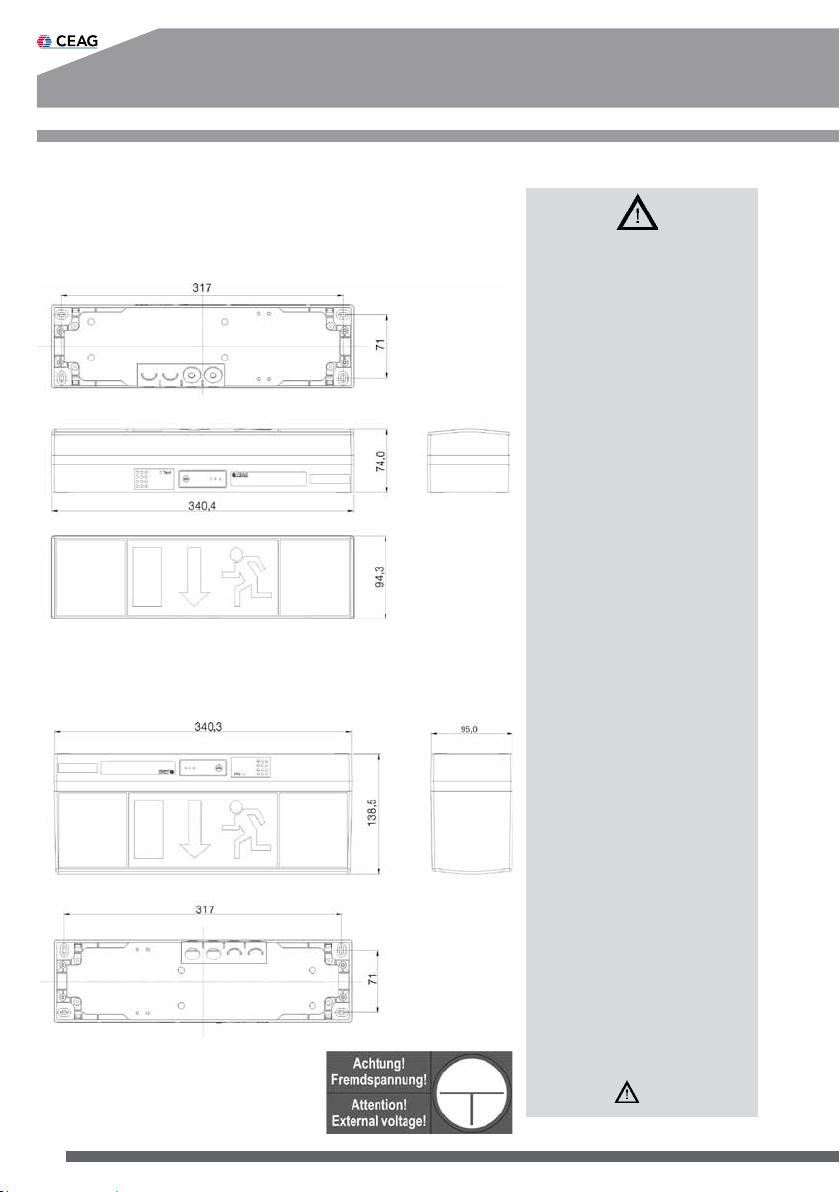
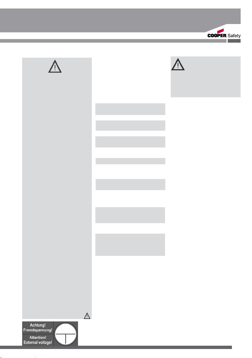
When working on the emer-
gency luminaire first cut off
mains (charging phase and
L’) and interrupt battery ope-
ration. Fig. 13 shows the indi-
cation label on the emergency
luminaire.
Prior to its initial operation,
the luminaire will have to be
checked in accordance with
the instructions as per section
Installation!
Carry out the marking of the
emergency luminaire: Assign
the circuit, the luminaire no.
and ID-No. and enter them.
The manual log book shall be
performed in compliance with
the national regulations. It is
not applicable by automatical
log book with the CG-Con-
troller CGLine!
Any foreign matter shall be
removed from the luminaire
prior to its initial operation!
Observe the national safe-
ty rules and regulations for
prevention of accidents as
well as the safety instructions
included in these operating
instruction marked with
3. Conformity with
Standards
Conforms to: EN 60 598-1,
EN 60 598-2-22, EN 1838, DIN.
Developed, manufactured and
tested in accordance with DIN
EN ISO 9001.
4. Technical data
Input voltage: 230/240 V AC
50 Hz
Rated current (AC): 70 mA
Power con-
sumption (AC): max.16VA (8W)
Lamp: 8 W/T16
Rated luminous flux
of the lamp: 450 lm
Rated luminous flux at the end
operating cycle:40%(phiE/phinom)
Insulation class: II
Protection category acc.
to EN 60529: IP 41
At option: IP 54
Accu: gas-tight,reloadable,
maintenance-free
Rated operating cycle:
1h: NC-accu 3.6V, 1.5Ah
3h: NC-accu 3.6V, 4.0Ah
Admissible ambient temperat.
maintained light: -5°C...+35°C
non maint. light: 0°C...+30°C
Supply terminals: 3 x 2.5 mm²
Bus terminals: 2 x 1.5 mm2
Weight: 58011-1/D 1.2kg
58011-3/D 1.4kg
58021-1/D 1.3kg
58021-3/D 1.6kg
Fig. 13
4.2 Brief Description/Area
of Application
As a self-contained luminaire
the STYLE Variant 58011/58021
CGLine emergency and
safety luminaire is suitable for
installations according to EN
50 172, DIN VDE 0100-718 and
DIN V VDE V 0108-100.
With the CEAG CG-Controller
CGLine 400 or the CGLine
WEB-Interface the selfcontained
luminaires can be monitored
centrally via a bus cable.
5. Installation
For the mounting and
operation of electrical
apparatus, the respec-
tive national safety regulations
as well as the general rules of
engineering will have to be ob-
served.
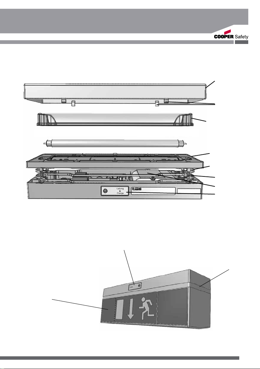
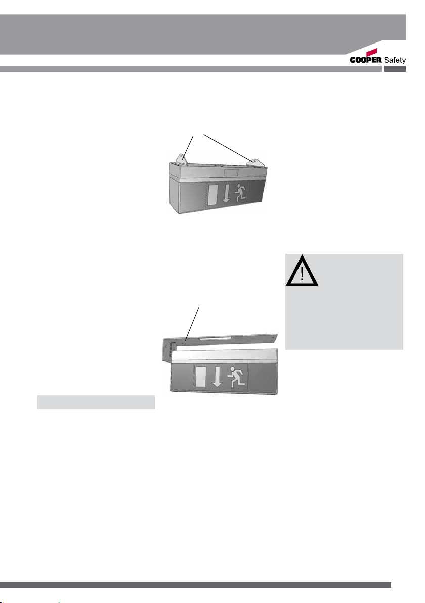
5.1 Assembly
Loosen the cover by pressing the
side panels of the cover (Fig. 1)
and lift it off the enclosure.
Remove the lamp from the lamp
fitting.
Loosen 2 snap-in hooks on the
long side of the top part of the
enclosure with a slotted screw-
driver and lift the top part of the
enclosure off the bottom part.
Depending on the installation
conditions, pierce the pre-drilled
cable entries on the side or the
back. Insert cable entry plugs
where necessary and punch or
cut one hole each for the cable
diameter used.
If the sealing lips are damaged,
the cable entry must be replaced
to preserve the degree of protec-
tion! Unused, but pierced cable
entries must be sealed with the
cable entry plug (IP degree of
protection).
Insert the cables in the luminaire
and attach the luminaire to the
wall or ceiling with appropriate,
adequately sized screws through
the 4 holes at the corners of the
enclosure (Fig. 4).
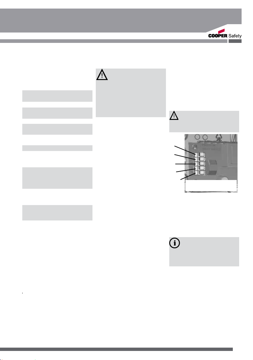
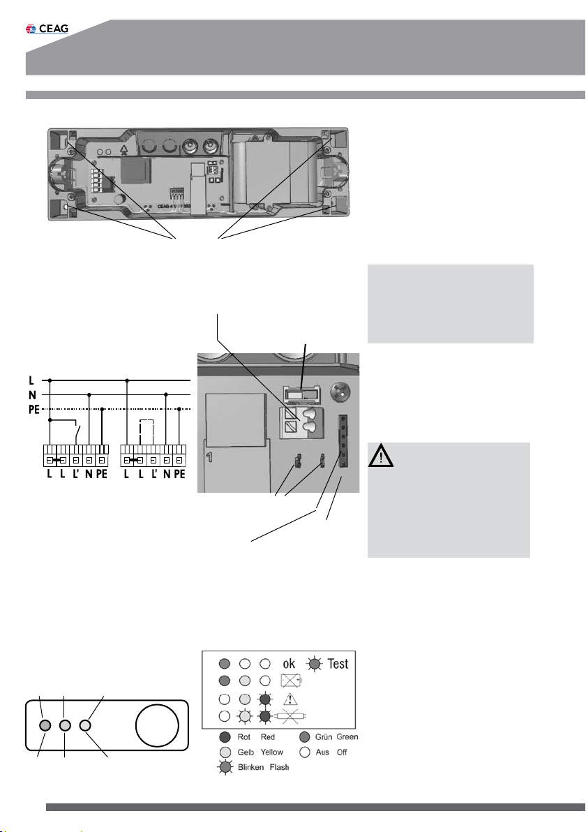
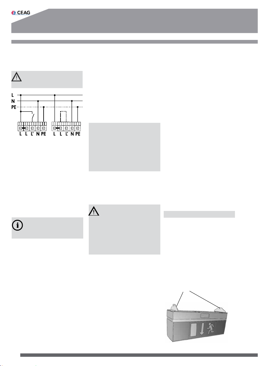
5.2 Mains Connection
Connect the mains cable to the
terminals N, L, L’ and PE, where
L is for unswitched permanent
supply to the electronics and L’
is used to switch the lamp on
and off via a light switch (Fig. 3).
PE must be connected as func-
tional earth by luminaires with
insulation class II (two)!
Optionally, every luminaire can
be operated with light switch-