Cebora CP-161 User manual

MANUALE DI ISTRUZIONI PER TORCE PLASMA CEBORA CP-161
INSTRUCTION MANUAL FOR CEBORA CP-161 PLASMA TORCHES
BEDIENUNGSANLEITUNG FÜR CEBORA CP-161 PLASMA BRENNER
MANUEL D’INSTRUCTIONS POUR TORCHES PLASMA CEBORA CP-161
MANUAL DE INSTRUCCIONES PARA ANTORCHAS PLASMA CEBORA CP-161
26/01/2018
3.300.235/C

2
CEBORA S.p.A - Via Andrea Costa, 24 -
40057 Cadriano di Granarolo - BOLOGNA - Italy
Tel. +39.051.765.000 - Fax. +39.051.765.222
I L'USO DI CONSUMABILI NON ORIGINALI CEBORA FA AUTOMATICAMENTE DECADERE OGNI
GARANZIA E/O RESPONSABILITÀ SU GENERATORI E TORCE PER IL TAGLIO AL PLASMA.
GB THE USE OF NON-GENUINE CEBORA CONSUMABLES AUTOMATICALLY VOIDS ANY
WARRANTY AND/OR RESPONSIBILITY ON PLASMA CUTTING POWER SOURCES AND TORCHES
D DIE GARANTIE UND/ODER HAFTUNG FÜR DIE STROMQUELLEN UND BRENNER ZUM
PLASMASCHNEIDEN VERFÄLLT AUTOMATISCH, WENN ANDERE ALS DIE ORIGINAL-
VERBRAUCHSTEILE VON CEBORA VERWENDET WERDEN.
F L'UTILISATION DE CONSOMMABLES NON ORIGINAUX CEBORA REND AUTOMATIQUEMENT
CADUQUE TOUTE GARANTIE ET/OU RESPONSABILITÉ CONCERNANT LES GÉNÉRATEURS
ET LES TORCHES POUR LE DÉCOUPAGE PLASMA
E EL USO DE CONSUMIBLES NO ORIGINALES CEBORA DETERMINA AUTOMÁTICAMENTE LA
INVALIDACIÓN DE TODA GARANTÍA Y/O RESPONSABILIDAD RESPECTO DE GENERADORES
Y ANTORCHAS PARA EL CORTE POR PLASMA.
P O USO DE CONSUMÍVEIS NÃO ORIGINAIS CEBORA ANULA AUTOMATICAMENTE QUALQUER
GARANTIA E/OU RESPONSABILIDADE DO FABRICANTE NOS GERADORES E MAÇARICOS DE
CORTE COM PLASMA.
SF EI-ALKUPERÄISTEN KULUTUSOSIEN KÄYTÖN SEURAUKSENA CEBORA MITÄTÖI AUTO-
MAATTISESTI KAIKKI TAKUUT JA/TAI VAPAUTUU KAIKESTA VASTUUSTA VIRTALÄHTEIDEN
JA PLASMALEIKKAUSPOLTINTEN OSALTA.
DK BRUG AF FORBRUGSMATERIALER, SOM IKKE ER FREMSTILLET AF CEBORA, MEDFØRER
AUTOMATISK BORTFALD AF ENHVER FORM FOR GARANTI OG/ELLER ANSVAR VEDRØREN-
DE STRØMKILDER OG SVEJSESLANGER TIL PLASMASKÆRING.
NL DOOR HET GEBRUIK VAN CONSUMPTIEMATERIAAL DAT NIET DOOR CEBORA GELEVERD
WORDT, VERVALT AUTOMATISCH ELKE GARANTIE EN/OF AANSPRAKELIJKHEID VOOR
GENERATOREN EN PLASMA SNIJTOORTSEN.
S VID ANVÄNDNING AV FÖRBRUKNINGSDELAR SOM INTE ÄR CEBORA ORIGINALDELAR BORT-
FALLER GARANTIN AUTOMATISKT OCH/ELLER TILLVERKAREN AVSÄGER SIG ALLT ANSVAR
FÖR GENERATORER OCH SLANGPAKET FÖR PLASMASKÄRNING.
PL UŻYCIE CZĘŚCI EKSPLOATACYJNYCH INNYCH NIŻ ORYGINALNE DOSTARCZANE PRZEZ
CEBORA UNIEWAŻNIA GWARANCJĘ ORAZ ZNOSI ODPOWIEDZIALNOŚĆ PRODUCENTA ZA
AGREGATY PLAZMOWE ORAZ PALNIKI DO CIĘCIA PLAZMOWEGO.
GR H ΧΡΗΣΗ ΜΗ ΑΥΘΕΝΤΙΚΩΝ ΑΝΑΛΩΣΙΜΩΝ CEBORA ΑΚΥΡΩΝΕΙ ΑΥΤΟΜΑΤΑ ΤΗΝ ΟΠΟΙΑΔΗΠΟ-
ΤΕ ΠΑΡΕΧΟΜΕΝΗ ΕΓΓΥΗΣΗ Η/ΚΑΙ ΕΥΘΥΝΗ ΕΠΙ ΤΩΝ ΓΕΝΝΗΤΡΙΩΝ ΚΑΙ ΤΩΝ ΦΑΚΩΝ ΚΟΠΗΣ
ΜΕ ΠΛΑΣΜΑ.

3
MANUALE DI ISTRUZIONI PER TORCE PLASMA CEBORA CP-161
Prima di utilizzare questa torcia, leggere attentamente il
presente manuale.
Questa torcia è costruita in stretta osservanza delle
prescrizioni in materia di sicurezza contenute nella
norma IEC 60974-7. In osservanza a quanto prescritto
da tali norme, la CEBORA SPA dichiara che questa
torcia si deve utilizzare solo con generatori CEBORA.
I ricambi ed i particolari di consumo sono parti
integrali della torcia, pertanto la CEBORA considera
manomissione della stessa l'utilizzo di particolari
NON ORIGINALI e declina quindi, in conformità
allo spirito della norma stessa, ogni responsabilità,
comprese quelle previste dal contratto di garanzia.
Qualsiasi uso non descritto, è da considerarsi NON
AMMESSO.
La messa in funzione, l'uso e la manutenzione vanno
esercitati da personale qualicato.
Attenersi inoltre alle norme antinfortunistiche vigenti.
1 - PREMESSA
Questa torcia, progettata per il taglio di materiali
elettroconduttori (metalli e leghe) mediante il
procedimento ad arco plasma, utilizza aria come gas
plasma e di raffreddamento.
Il taglio ad "ARCO PLASMA" avviene per l'alta temperatura
generata da un arco elettrico concentrato, quindi
possono innescarsi situazioni altamente pericolose.
E' indispensabile pertanto tenere nella massima
considerazione il capitolo riguardante le PRECAUZIONI
DI SICUREZZA descritto nel manuale del generatore al
quale è collegata la torcia.
Non è previsto, inoltre, che le torce debbano funzionare
sotto la pioggia o neve o in condizioni equivalenti.
Il presente manuale deve essere conservato con cura,
in un luogo noto all'operatore. Dovrà essere consultato
ogni volta che vi sono dubbi, dovrà seguire tutta la vita
operativa della macchina e dovrà essere impiegato per
l'ordinazione delle parti di ricambio.
2 DATI TECNICI
Corrente di taglio massima I2 = 160A D.C.
Fattore di servizio X = 60% con I2 = 160A.
Fattore di servizio X = 100% con I2 = 120A.
Tensione di lavoro U2 = 140V (distanza ugello-pezzo
4mm).
Tensione di lavoro U2 = 100V (ugello a contatto con il
pezzo).
Pressione di lavoro con cavo 6m = 5,0 bar (0,5 MPa).
Pressione di lavoro con cavo 12m = 5,4 bar (0,54 MPa).
Portata aria totale = 210 litri/minuto.
3 ACCESSORI E PARTI DI CONSUMO (g.1)
4 SICUREZZA
Questa torcia è provvista di una sicurezza elettrica,
posta sul corpo torcia, per evitare che vi siano tensioni
pericolose quando si sostituiscono l'ugello, l'elettrodo,
il diffusore o il portaugello. E’ conforme alla norma IEC
60974-7 la quale prescrive che l'ugello posto verticalmente
su un piano orizzontale, essendo parte in tensione, non
possa essere toccato dal dito di prova convenzionale le
cui caratteristiche sono indicate dalla norma stessa.
5 MANUTENZIONE TORCIA
Togliere sempre l'alimentazione alla macchina prima di
ogni intervento.
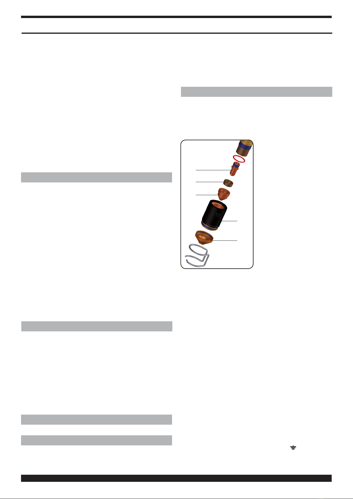
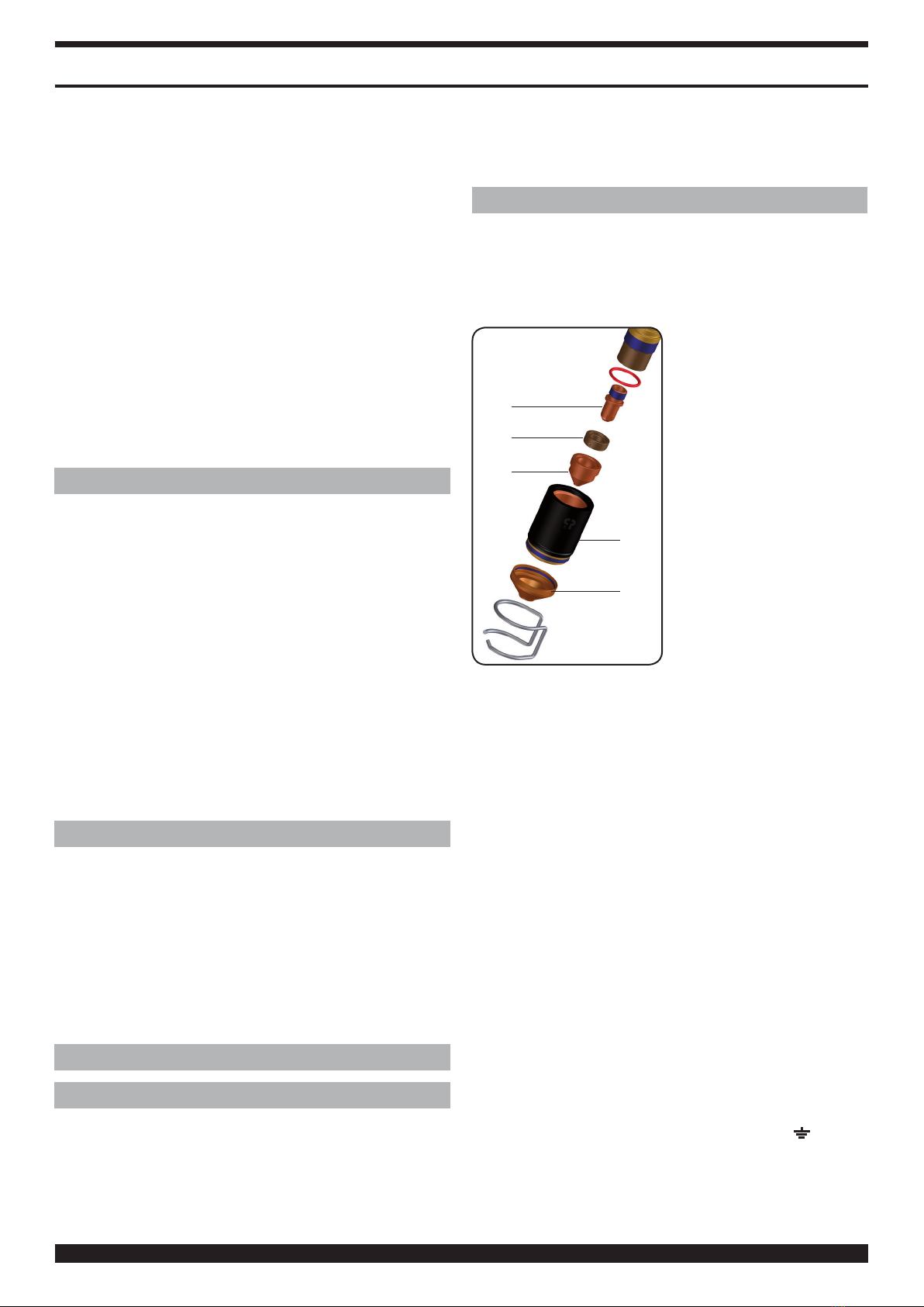
5.1 SOSTITUZIONE DEI CONSUMABILI
C
B
E
D
Fig. 2
F
In riferimento alla Fig.2 , i
particolari soggetti ad usura
sono: l'elettrodo C, il diffusore
B, l'ugello Ee la protezione
ugello F. Questi devono essere
sostituiti dopo aver svitato il
portaugello D. L'elettrodo C
deve essere sostituito quando
presenta un cratere al centro
profondo circa 1,5 mm.
ATTENZIONE: per svitare
l'elettrodo non esercitare
sforziimprovvisimaapplicare
una forza progressiva no
a provocare lo sbloccaggio
del letto. L'elettrodo nuovo
deve essere avvitato nella
sede e bloccato senza
stringere a fondo.
L' u g e l l o Eva sostituito quando presenta il foro centrale
rovinato oppure allargato rispetto a quello del particolare
nuovo. Una ritardata sostituzione dell'elettrodo e
dell'ugello provoca un eccessivo riscaldamento delle
parti che può pregiudicare la durata del diffusore B.
Assicurarsi che, dopo la sostituzione, il portaugello Dsia
stretto a sufcienza.
ATTENZIONE: avvitare il portaugello Dsul corpo
torcia solo con l'elettrodo C, il diffusore Be l'ugello E
montati. La mancanza di tali particolari compromette
il funzionamento dell'apparecchio ed in particolare la
sicurezza dell'operatore.
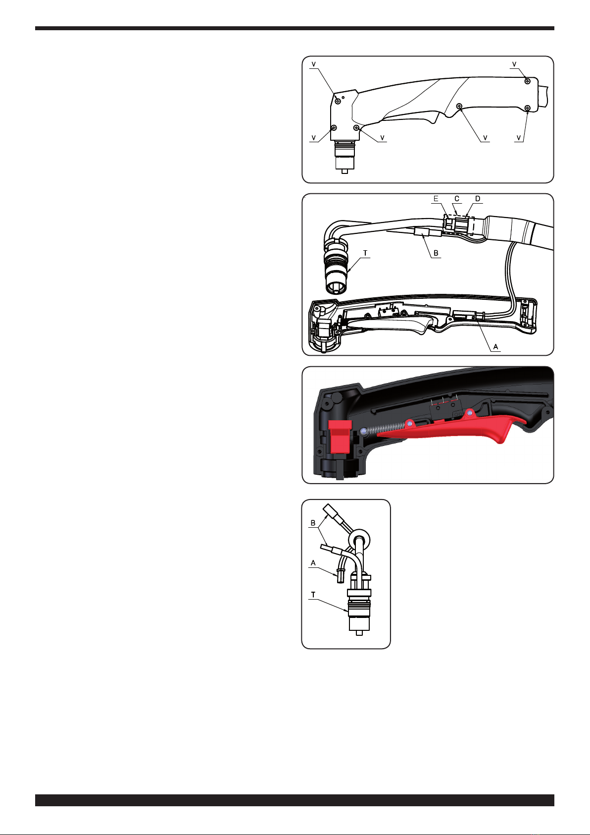
5.2 SOSTITUZIONE DELLA TORCIA
Le macchine con marchio S, progettate per lavorare in
ambienti a rischio accresciuto, sono provviste di una
protezione che obbliga l'uso di un utensile per montare
e smontare la torcia.
Svitare le viti che ssano la protezione alla macchina,
svitare la ghiera dell'attacco centralizzato, slare la
protezione.
Sostituire la torcia ed eseguire a ritroso le operazioni
precedenti.
Collegare il cavo giallo/verde al morsetto ( ) predisposto
sul generatore (solo per CP 161 DAR).

4
Nota 1:
• Non ammaccare il perno portacorrente e non piegare
gli spinotti del raccordo della torcia.
Nota 2:
• Con la torcia CP 161 DAR, utilizzata su macchine
sprovviste di circuito interfaccia, lo start si ottiene
mediante i li del cavetto AB (Fig. 10). In questo caso, a
ne taglio, il contatto di start deve essere portato in
posizione aperto (OFF).
• Con la torcia CP 161 DAR, utilizzata su macchine
provviste di circuito interfaccia, i li del cavetto AB
devono essere mantenuti in corto circuito.
5.3 SOSTITUZIONE DEL CORPO TORCIA
QUESTA PARTE È DESTINATA ESCLUSIVAMENTE AL
PERSONALE QUALIFICATO.
Fig. 1

5
5.3.1 Sostituzione corpo torcia CP161 MAR
• Svitare le 6 viti Vdi Fig.3 e togliere l’impugnatura sinistra.
• Con riferimento alla Fig.4, sollevare il corpo torcia T con
cavo e disconnettere la connessione A(pulsante) e la
connessione B(arco pilota) facendo attenzione che i
componenti del gruppo pulsante (vedi Fig.5) rimangano
nella posizione originale.
• Togliere il tubetto termorestringente Ce svitare il dado
D (chiave 13) tenendo ssato il raccordo E(chiave 11).
• Sostituire il corpo torcia.
• Avvitare i raccordi De Erispettando l’orientamento
indicato in Fig.6.
• Stringere i raccordi, inserire il tubetto termorestringente C
riscaldandolo mediante una piccola sorgente di calore.
• Collegare la connessione B, inserire il corpo torcia
nella sede dell’impugnatura ed inne collegare la
connessione Ainserendola all’interno dell’impugnatura
come indicato in gura 4.
• Riposizionare l’impugnatura sinistra facendo attenzione
a non schiacciare alcun lo tra i bordi di essa.
• Riavvitare le 6 viti V.
5.3.2 Sostituzione corpo torcia CP161 DAR
• Togliere la fascetta F1 di Fig.7 e slare all’indietro la
calza;
• Svitare il grano Ge successivamente il manico Mquindi
tirarlo all’indietro sino a mostrare tutti i cavi (vedi Fig.8).
• Disconnettere la connessione A(pulsante) e la
connessione B(arco pilota).
• Togliere il tubetto termorestringente Ce svitare il dado
D (chiave 13) tenendo ssato il raccordo E (chiave 11).
• Sostituire il corpo torcia.
• Avvitare i raccordi Ded Erispettando l’orientamento
indicato in Fig.9.
• Stringere i raccordi, inserire il tubetto termorestringente
Criscaldandolo mediante una piccola sorgente di
calore, avendo cura di coprire interamente i raccordi.
• Ricollegare le connessioni Ae B, riavvitare il manico M
e, successivamente, il grano G.
• Riportare la calza sull’impugnatura e stringere la
fascetta F1.
5.4 SOSTITUZIONE DELL’IMPUGNATURA CON
PULSANTE CP-161 MAR
• Svitare le 6 viti Vdi Fig.3 e togliere l’impugnatura
sinistra.
• Con riferimento alla Fig.4, sollevare il corpo torcia con
cavo e disconnettere la connessione A(pulsante).
• Sostituire l’impugnatura con pulsante, collegare la
connessione Ainserendola all’interno dell’impugnatura,
come indicato in gura 4, ed inne posizionare il corpo
torcia con cavo nella sede dell’impugnatura destra.
• Fissare la parte sinistra dell’impugnatura, facendo
attenzione a non schiacciare i li tra i bordi di essa, e
riavvitare le 6 viti V.
5.5 SOSTITUZIONE DEL CAVO CON ATTACCO
CENTRALIZZATO.
5.5.1 CP-161 MAR
Fig. 6
• Svitare le 6 viti Vdi Fig.3 e togliere
l’impugnatura sinistra sx. Con
riferimento alla Fig.4, sollevare il
corpotorciaconcavoedisconnettere
la connessione A(pulsante) e la
connessione B(arco pilota).
•Togliereil tubettotermorestringente
Ce svitare il dado D(chiave 13)
tenendo ssato il raccordo E (chiave
11).
• Sostituire il cavo torcia, avvitare
manualmente i raccordi Ded
Eavendo cura di rispettare
l’orientamento indicato in Fig.6.
• Stringere i raccordi, inserire il tubetto termorestringente
Criscaldandolo mediante una piccola sorgente di
calore.
• Collegare la connessione B, inserire il corpo torcia
nella sede dell’impugnatura ed inne collegare la
connessione Ainserendola all’interno dell’impugnatura
come indicato in gura 4.
• Riposizionare l’impugnatura sinistra facendo attenzione
a non schiacciare alcun lo tra i bordi di essa.
• Riavvitare le 6 viti V.
Fig. 3
Fig. 4
Fig. 5

6
5.5.2 CP161 DAR
• Togliere la fascetta F1 di Fig.7 e slare all’indietro la
calza.
• Svitare il grano G e successivamente il manico Mquindi
tirarlo all’indietro sino a mostrare tutti i cavi (vedi Fig.8);
• Disconnettere la connessione A(pulsante) e la
connessione B (arco pilota).
• Togliere il tubetto termorestringente Ce svitare il dado
D(chiave 13) tenendo fermo il raccordo E (chiave 11).
• Sostituire il cavo torcia.
• Avvitare i raccordi Ded Erispettando l’orientamento
indicato in Fig.9.
• Stringere i raccordi, inserire il tubetto termorestringente
Criscaldandolo mediante una piccola sorgente di
calore, avendo cura di coprire interamente i raccordi.
• Ricollegare le connessioni Ae B, riavvitare il manico M
e, successivamente, il grano G.
• Riportare la calza sull’impugnatura e stringere la
fascetta F1.
5.6 SOSTITUZIONE DELL' ATTACCO
CENTRALIZZATO.
Fig. 10
AB
W
T
M
X
I1
Z
Y Y1
N
K2
PJ
AC
Togliere la molla Pe tagliare le fascette che fermano
il cavo J. Aprire la copertura Wsvitando le relative 4
viti di ssaggio e successivamente la vite M. Slare
gli spinotti del cavi di controllo X e Z. Annotarsi il
numero di posizione di ciascun pin quindi slare il
cavallotto T e gli spinotti dei cavi rossi dell'arco pilota
Ye Y1. Tagliare il tubo isolante K2 e svitare il corpo N
Fig. 7
Fig. 8
Fig. 9

7
dal raccordo I1. Montare il nuovo attacco eseguendo
a ritroso le operazioni precedenti. Per il bloccaggio del
letto del corpo N utilizzare adesivo sigillante per letti.
Per non compromettere l'efcienza della sicurezza è
importante che i contatti del corpo N siano collegati
nel modo seguente: gli spinotti Y e Y1 dei cavi rossi
dell'arco pilota ai contatti 5 e 6, lo spinotto X del cavo
J al contatto 1, lo spinotto Z del cavo J al contatto 9.
Ricollegare il cavallotto Tcome annotato precedente-
mente.
5.7 AVVERTENZE
Assicurarsi periodicamente che il cavo della torcia sia
integro e non presenti tagli o segni di usura eccessiva.
Nel caso, procedere alla sua immediata sostituzione.

8
INSTRUCTION MANUAL FOR CEBORA CP-161 PLASMA TORCHES
Before using this welding torch, read carefully this manual.
This welding torch is made in accordance with IEC
60974-7 standard safety requirements. According
to the above standard requirements CEBORA
SPA declares that this welding torch must be used
solely with CEBORA power sources. Spare parts
and consumables are integral part to this welding
torch, therefore CEBORA considers the use of parts
that are not CEBORA genuine parts as a tampering
action and consequently, in accordance with the
spirit of this same standard CEBORA assumes no
responsibility including those provided for in the
guarantee contract.
Any use which is not described has to be considered as
NOT ALLOWED.
Starting up, operation and maintenance must be carried
out by skilled personnel.
Accident prevention regulations in force should be
respected.
1 - GENERAL
This welding torch, designed for plasma arc cutting of
electro-conducting materials (metals and alloys) uses air
as plasma gas and cooling agent.
The “PLASMA ARC” cutting is the result of the high
temperature generated by a concentrated electric arc
and therefore highly hazardous situations may occur. It is
essential to pay especially close attention to the chapter
on SAFETY PRECAUTIONS in the manual of the power
source to which the welding torch is connected.
These welding torches should not be used under rain or
snow or equivalent condition.
This manual must be stored carefully in a place familiar
to the operator using the welding torch. It must be
consulted whenever doubts arise and be kept for the
entire welding torch life-span; it will also be used for
ordering replacement parts.
2 TECHNICAL SPECIFICATIONS
Maximum cutting current I2 = 160A D.C.
Duty cycle X = 60% with I2= 160A.
Duty cycle X = 100% with I2= 120A.
Working voltage U2. = 140V (nozzle-piece distance:
4mm).
Working voltage U2 = 100V (nozzle contacts the piece).
Working pressure with a 6m = 5.0 bar (0.5 MPa) cable.
Working pressure with a 12m = 5.4 bar (0.54 MPa) cable.
Total air capacity = 210 litres/minute.
3 ACCESSORIES AND CONSUMABLES (g .1)
4 SAFETY
This welding torch is equipped with an electric safety
devise located on the welding torch body to avoid any
dangerous voltage when the nozzle, the electrode,
the swirl ring or the nozzle holder are replaced. It is in
accordance with IEC 60974-7 Standard which requires
that when a live nozzle is vertically located on a at
surface it should not be touched with the conventional
test nger whose characteristics are specied in the
standard.
5 WELDING TORCH MAINTENANCE
Always shut off the unit before any maintenance
operation
5.1 REPLACING THE CONSUMABLES
C
B
E
D
Fig. 2
F
Making reference to Fig. 2 ,
parts subject to wear are as
follows: electrode C, swirl
ring B, nozzle E and nozzle
protection F. These should
be replaced after unscrewing
the nozzle holder D.
Electrode Cmust be
replaced when it shows an
approx 1.5 mm deep crater
at the centre.
WARNING: When
unscrewing the electrode
do not force it but apply a
progressive strength until
the thread is disengaged.
The new electrode must
be screwed in its seat and
locked without tightening all
the way down.
Nozzle Eis to be replaced when its central hole is
damaged or enlarged as compared to a new one.
Delayed replacements of electrode and nozzle cause
overheating , which can reduce swirl ring Blife. After
these replacements, check that the nozzle holder Dis
accurately tightened.
WARNING: screw the nozzle holder Donto the welding
torch body only when electrode C, swirl ring Band
nozzle Eare assembled. If these elements are not
assembled the equipment operation is jeopardized as
well as the operator’s safety.
5.2 REPLACEMENT OF THE WELDING TORCH
The units with Smark, designed to operate in highly
hazardous ambient are equipped with a protection
device which requires the use of a tool to assemble and
disassemble the welding torch.
Unscrew the screws that fasten the protection device
to the unit, unscrew the ring nut of the central adapter,
remove the protection device.
Replace the welding torch and follow the previous
instructions in reverse direction.
Connect the yellow/green cable to terminal ( ) on the
power source (CP 161 DAR only).
Note 1:
• Do not dent the contact tip, do not bend the welding
torch tting pins.

9
Note 2:
• With welding torch CP 161 DAR, used on units with no
interface circuit, operation start is obtained with cable
wires AB. In this case when cutting operation is
completed, the start contact must be positioned in
open position (OFF).
• With welding torch CP 161 DAR, used on units with
interface circuit, the cable AB wires must be always
short circuited.
5.3 REPLACING THE WELDING TORCH BODY
THIS SECTION IS RESERVED TO SKILLED PERSONNEL
ONLY.
5.3.1 Replacing the welding torch body CP161 MAR
• Unscrew the 6 screws VFig.3 and remove the LH grip.
• With reference to Fig.4, lift the welding torch body Twith
cable and disconnect connector A(push-button) and
connector B(pilot arc) making sure that the push-button
Fig. 1

10
components (see Fig. 5) remain in the original position.
Fig. 6
• Remove heat-shrinking hose C
and unscrew nut D (wrench #13) by
keeping tting E(wrench #11)
fastened.
• Replacing the welding torch
body.
• Screw in ttings Dand E
according to the arrow direction -
Fig. 6.
• Tighten ttings, introduce the
heat-shrinking hose C and use a
small heat source to warm it up.
• Connect connector B, introduce
the welding torch body into the
grip seat and then connect connector Aby introducing
it inside the grip as shown in gure 4.
• Reposition LH grip making sure not to atten any wire
between the grip rims.
• Screw in the 6 screws V again.
5.3.2 Replacing the welding torch body CP161 MAR
• Remove clamp F1 Fig.7 and extract the sleeve;
• Unscrew the retention dowel Gand then handle M, pull
it back until all cables are shown (see Fig. 8).
• Disconnect connector A(push-button) and connector
B(pilot arc).
• Remove heat shrinking hose Cand unscrew nut D
(wrench #13) by keeping tting E(wrench #11) fastened.
• Replacing the welding torch body.
• Screw in ttings Dand Eaccording to the arrow
direction - Fig .9.
• Tighten ttings, introduce the heat-shrinking hose C
and use a small heat source to warm it up. Make sure
that ttings are completely covered.
• Reconnect connectors Aand B, screw in the handle M
and, then the retention dowel G.
• Reposition the sleeve onto the handle and tighten the
clamp F1.
5.4 REPLACING THE GRIP WITH PUSH-BUTTON CP-
161 MAR
• Unscrew the 6 screws VFig.3 and remove the LH grip.
• With reference to Fig.4, lift the welding torch body with
cable and disconnect connector A(push-button) .
• Replace the grip with push-button, connect connector
A and introduce it inside the grip, as shown in gure 4,
and then position the welding torch body with cable
inside the RH grip seat.
• Fasten the LH side of the grip making sure not to atten
any wire between the grip rims and then screw the 6
screws Vagain.
5.5 REPLACING THE CABLE WITH CENTRAL
ADAPTER.
5.5.1 CP-161 MAR
• Unscrew the 6 screws VFig.3 and remove the LH grip.
With reference to Fig.4, lift the welding torch body with
cable and disconnect connector A(push-button) and
connector B(pilot arc).
• Remove heat shrinking hose Cand unscrew nut D
(wrench #13) by keeping tting E(wrench #11) fastened.
• Replace the welding torch cable, manually screw
ttings Dand Eaccording to the arrow direction - Fig.6.
• Tighten ttings, introduce the heat-shrinking hose C
and use a small heat source to warm it up.
• Connect connector B, introduce the welding torch
body into the grip seat and then connect connector A
by introducing it inside the grip as shown in gure 4.
• Reposition LH grip making sure not to atten any wire
between the grip rims.
• Screw in the 6 screws Vagain.
5.5.2 CP161 DAR
• Remove clamp F1 Fig.7 and extract the sleeve.
• Unscrew the retention dowel Gand then handle M, pull
it back until all cables are shown (see Fig. 8);
• Disconnect connector A(push-button) and connector
B(pilot arc).
• Remove heat shrinking hose Cand unscrew nut D
(wrench #13) by keeping tting E(wrench #11) fastened.
• Replacing the welding torch cable.
• Screw in ttings Dand Eaccording to the arrow
Fig. 3
Fig. 4
Fig. 5

11
direction - Fig.9.
• Tighten ttings, introduce the heat-shrinking hose C
and use a small heat source to warm it up. Make sure
that ttings are completely covered.
• Reconnect connectors Aand B, screw in the handle M
and then the retention dowel G.
• Reposition the sleeve onto the handle and tighten the
clamp F1.
5.6 REPLACING THE CABLE WITH CENTRAL
ADAPTER.
Fig. 10
AB
W
T
M
X
I1
Z
Y Y1
N
K2
PJ
AC
Remove spring Pand cut the clamps that fasten the cable
J. Open the cover Wby unscrewing the 4 set screws and
then screw M. Remove pins of the control cable Xand
Z. Take note of the position of each pin and then remove
the U-bolt Tand the pins of the pilot arc red cables Y
and Y1. Cut the isolating hose K2 and unscrew body N
from tting I1. Assemble the new tting and follow the
previous instructions in reverse direction. Use thread
sealer to lock the Nbody thread. To avoid jeopardizing
the safety efciency, the body contacts N must be
connected as follows: pins Y and Y1 of pilot arc red
cables to contacts 5 and 6, pin X of cable J to contact
1, pin Z of cable J to contact 9.
Reconnect U-bolt Tas described above.
5.7 WARNINGS
Periodically make sure that the welding torch cable is
intact and has no cuts or excessive wear. Replace it
immediately if needed.
Fig. 7
Fig. 8
Fig. 9

12
Vor Gebrauch dieses Brenners die vorliegende
Betriebsanleitung sorgfältig lesen.
Die Konstruktion dieses Brenners entspricht den
Sicherheitsanforderungen der Norm IEC 60974-7.
Nach Maßgabe der Vorschriften dieser Norm erklärt
die Firma CEBORA SPA, dass dieser Brenner nur mit
Stromquellen von CEBORA betrieben werden darf.
Die Ersatz- und Verbrauchsteile sind Bestandteile des
Brenners. CEBORA betrachtet daher den Gebrauch
von ANDEREN ALS ORIGINALTEILEN als unbefugte
Veränderung und lehnt im Sinne dieser Norm jede
Haftung ab, die vom Garantievertrag vorgesehene
Haftung eingeschlossen.
Jeder nicht beschriebene Gebrauch ist als UNZULÄSSIG
anzusehen.
Inbetriebnahme, Betrieb und Wartung müssen durch
Fachpersonal erfolgen.
Außerdem sind die geltenden Unfallverhütungsvorschrif-
ten zu beachten.
1 - VORBEMERKUNG
Dieser Brenner, der zum Schneiden von elektrisch
leitenden Werkstoffen (Metalle und Legierungen) mit
einem Plasmalichtbogen konzipiert wurde, arbeitet mit
Luft als Plasma- und Kühlgas.
Beim PLASMALICHTBOGENSCHNEIDEN entsteht
eine hohe, von einem eingeschnürten Lichtbogen
erzeugte Temperatur; daher kann es zu hochgradig
gefährlichen Situationen kommen. Das die
SICHERHEITSVORSCHRIFTEN betreffende Kapitel in der
Betriebsanleitung der Stromquelle, an die der Brenner
angeschlossen ist, muss daher besonders aufmerksam
gelesen werden.
Der Betrieb des Brenners im Regen, bei Schneefall oder
unter vergleichbaren Bedingungen ist nicht vorgesehen.
Die vorliegende Betriebsanleitung muss sorgfältig an
einem dem Benutzer bekannten Ort aufbewahrt werden.
Sie muss in allen Zweifelsfällen zu Rate gezogen werden
und das Gerät während seiner gesamten Lebensdauer
begleiten; außerdem muss sie zur Ersatzteilbestellung
herangezogen werden.
2 TECHNISCHE DATEN
Maximaler Schneidstrom I2 = 160 ADC
Relative Einschaltdauer X = 60% bei I2 = 160A
Relative Einschaltdauer X = 100% bei I2 = 120A
Arbeitsspannung U2 = 140V (Abstand Düse/Werkstück 4
mm).
Arbeitsspannung U2 = 100V (Düse berührt Werkstück).
Arbeitsdruck mit Schlauchpaket von 6 m = 5,0 bar (0,5
MPa).
Arbeitsdruck mit Schlauchpaket von 12 m = 5,4 bar (0,54
MPa).
Gesamtluftvolumen = 210 Liter/Minute.
3 ZUBEHÖR- UND VERBRAUCHSTEILE (Abb. 1)
4 SICHERHEIT
Dieser Brenner verfügt über eine elektrische
Sicherheitsvorrichtung auf dem Brennerkörper, die
verhindert, dass beim Austauschen der Düse, der
Elektrode, des Diffusors oder der Düsenspannhülse
gefährliche Spannungen am Brenner anliegen. Sie
entspricht der Norm IEC 60974-7, die vorschreibt,
dass es nicht möglich sein darf, die senkrecht auf einer
waagrechten Ebene angeordnete Düse, die ein aktives Teil
ist, mit dem Prüfnger zu berühren, dessen Eigenschaften
von der Norm festgelegt werden.
5 WARTUNG DES BRENNERS
Das Gerät vor jedem Eingriff von der Stromquelle
trennen.
5.1 AUSWECHSELN DER VERBRAUCHSTEILE
C
B
E
D
Abb. 2
F
Die in Abb. 2 gezeigten
Verbrauchsteile sind: die
Elektrode C, der Diffusor B,
die Düse Eund der
Düsenschutz F. Sie können
ausgewechselt werden,
nachdem die Düsen-
spannhülse Dabgeschraubt
wurde. Die Elektrode Cist
auszuwechseln, wenn sie in
der Mitte einen Krater von
rund 1,5 mm Tiefe aufweist.
ACHTUNG: Zum
Ausschrauben der Elektrode
die Kraft nicht ruckweise
aufwenden, sondern
allmählich erhöhen, bis sich
das Gewinde löst. Die neue
Elektrode in ihre Aufnahme
schrauben und blockieren, ohne sie jedoch bis zum
Anschlag anzuziehen.
Die Düse Eist auszuwechseln, wenn die Mittelbohrung
beschädigt ist oder sich im Vergleich zur Bohrung einer
neuen Düse erweitert hat. Werden die Elektrode oder die
Düse nicht rechtzeitig ausgewechselt, führt dies zu einer
Überhitzung der Teile und infolgedessen möglicherweise
zueiner Verkürzungder Lebensdauer desDiffusorsB. Nach
dem Austausch sicherstellen, dass die Düsenspannhülse
Dfest genug angezogen ist.
ACHTUNG: Die Düsenspannhülse Ddarf erst auf den
Brennerkörper geschraubt werden, nachdem die Elektrode
C, der Diffusor Bund die Düse Emontiert wurden.
Wenn diese Teile fehlen, kann es zu Fehlfunktionen
des Geräts und insbesondere zu einer Gefährdung des
Bedienungspersonals kommen.
5.2 AUSWECHSELN DES BRENNERS
Die Geräte mit dem Prüfzeichen S, die für den Betrieb
in Umgebungen mit erhöhter Gefährdung konzipiert
sind, verfügen über eine Schutzeinrichtung, welche die
Verwendung eines Werkzeugs zum Aus- und Einbauen
des Schlauchpakets erforderlich macht.
BEDIENUNGSANLEITUNG FÜR CEBORA CP-161 PLASMA BRENNER

13
Die Schrauben, mit denen die Schutzeinrichtung am
Gerät befestigt ist, ausschrauben, die Überwurfmutter
des Hauptanschlusses lösen und die Schutzeinrichtung
herausziehen.
Den Brenner austauschen und die zuvor beschriebenen
Arbeitsschritte in der umgekehrten Reihenfolge ausführen.
Den gelb-grünen Schutzleiter an die Klemme ( ) auf der
Stromquelle anschließen (nur bei CP 161 DAR).
Anmerkung 1:
• Darauf achten, den Stromkontaktzapfen nicht
zu beschädigen und die Kontaktstifte des
Brenneranschlusses nicht zu verbiegen.
Anmerkung 2:
• Wird der Brenner CP 161 DAR mit Geräten ohne
Schnittstellenschaltung verwendet, erfolgt der Start mit
Hilfe der Drähte des Kabels AB. In diesem Fall muss
Abb. 1

14
der Start-Kontakt am Ende des Schneidvorgangs in
die geöffnete Stellung gebracht werden (OFF).
• Wird der Brenner CP 161 DAR mit Geräten mit
Schnittstellenschaltung verwendet, müssen die Drähte
des Kabels AB kurzgeschlossen sein.
5.3 AUSWECHSELN DES BRENNERKÖRPERS
DIESER ABSCHNITT RICHTET SICH AUSSCHLIESSLICH
AN DEN FACHMANN.
5.3.1 Auswechseln des Brennerkörpers CP161 MAR
• Die 6 Schrauben V(siehe Abb. 3) ausschrauben und die
linke Griffhälfte entfernen.
• Wie in Abb 4 gezeigt den Brennerkörper Tmit dem
Kabel anheben und die Verbindungen A(Taster) und B
(Pilotlichtbogen) lösen. Hierbei darauf achten, dass die
Komponenten der Taster-Baugruppe (siehe Abb. 5) in
ihrer ursprünglichen Position bleiben.
• Den Wärmeschrumpfschlauch Centfernen und die
Mutter D(13er Schlüssel) ausschrauben; hierbei das
Anschlussstück Emit einem 11er Schlüssel blockieren.
• Den Brennerkörper auswechseln.
Abb. 6
• Die Anschlussstücke Dund E
verschrauben; hierbei die in Abb. 6
angegebene Ausrichtung beachten.
• Die Anschlussstücke festziehen,
den Wärmeschrumpf- schlauch
Caufziehen und mit einer kleinen
Wärmequelle erwärmen.
• Die Verbindung Bwieder
herstellen, den Brennerkörper in den
Griff einsetzen und schließlich die
Verbindung Awie in der Abbildung 4
gezeigt einsetzen und anschließen.
• Die linke Griffhälfte wieder
anbringen. Hierbei darauf achten, keinen Draht zwischen
den Kanten der zwei Griffhälften einzuquetschen.
• Die 6 Schrauben Vwieder einschrauben.
5.3.2 Auswechseln des Brennerkörpers CP161 DAR
• Den Kabelbinder F1 entfernen und das Drahtgeecht
zurückziehen.
• Den Gewindestift Gausschrauben und dann den Griff
Mabschrauben und nach hinten ziehen, so dass alle
Kabel freiliegen (siehe Abb. 8).
• Die Verbindungen A(Taster) und B(Pilotlichtbogen)
lösen.
• Den Wärmeschrumpfschlauch Centfernen und die
Mutter D(13er Schlüssel) ausschrauben; hierbei das
Anschlussstück Emit einem 11er Schlüssel blockieren.
• Den Brennerkörper auswechseln.
• Die Anschlussstücke Dund Everschrauben; hierbei die
in Abb. 9 angegebene Ausrichtung beachten.
• Die Anschlussstücke festziehen, den Wärmeschrumpf-
schlauch Caufziehen und mit einer kleinen Wärmequelle
erwärmen. Darauf achten, dass die Anschlussstücke
vollständig bedeckt werden.
• Die Verbindungen Aund Bwieder herstellen, den
Griff Manschrauben und dann den Gewindestift G
einschrauben.
• Das Drahtgeecht wieder über den Griff ziehen und den
Kabelbinder festziehen.
5.4 AUSWECHSELN DES GRIFFS MIT TASTER CP-
161 MAR
• Die 6 Schrauben V(siehe Abb. 3) ausschrauben und die
linke Griffhälfte entfernen.
• Wie in Abb. 4 gezeigt den Brennerkörper mit dem Kabel
anheben und die Verbindung A(Taster) lösen.
• Den Griff mit Taster auswechseln. Dann die Verbindung
Awie in Abb. 4 gezeigt in den Griff einsetzen und
anschließen und schließlich den Brennerkörper mit
Kabel wieder in die rechte Griffhälfte einsetzen.
• Die linke Griffhälfte befestigen. Hierbei darauf achten,
keinen Draht zwischen den Kanten der zwei Griffhälften
einzuquetschen. Dann die 6 Schrauben Vwieder
einschrauben.
5.5 AUSWECHSELN DES KABELS MIT
ZENTRALANSCHLUSS
5.5.1 CP-161 MAR
Abb. 3
Abb. 4
Abb. 5

15
• Die 6 Schrauben V(siehe Abb. 3) ausschrauben und
die linke Griffhälfte entfernen. Wie in Abb. 4 gezeigt
den Brennerkörper mit dem Kabel anheben und die
Verbindungen A(Taster) und B(Pilotlichtbogen) lösen.
• Den Wärmeschrumpfschlauch Centfernen und die
Mutter D(13er Schlüssel) ausschrauben; hierbei das
Anschlussstück Emit einem 11er Schlüssel blockieren.
• Das Brennerkabel austauschen. Die Anschlussstücke D
und Evon Hand verschrauben; hierbei auf die in Abb. 6
gezeigte Ausrichtung achten.
• Die Anschlussstücke festziehen, den Wärmeschrumpf-
schlauch Caufziehen und mit einer kleinen Wärmequelle
erwärmen.
• Die Verbindung Bwieder herstellen, den Brennerkörper
in den Griff einsetzen und schließlich die Verbindung
Awie in der Abbildung 4 gezeigt einsetzen und
anschließen.
• Die linke Griffhälfte wieder anbringen. Hierbei darauf
achten, keinen Draht zwischen den Kanten der zwei
Griffhälften einzuquetschen.
• Die 6 Schrauben Vwieder einschrauben.
5.5.2 CP161 DAR
• Den Kabelbinder F1 entfernen und das Drahtgeecht
zurückziehen.
• Den Gewindestift Gausschrauben und dann den Griff
M abschrauben und nach hinten ziehen, so dass alle
Kabel freiliegen (siehe Abb. 8).
• Die Verbindungen A(Taster) und B(Pilotlichtbogen)
lösen.
• Den Wärmeschrumpfschlauch Centfernen und die
Mutter D (13er Schlüssel) ausschrauben; hierbei das
Anschlussstück Emit einem 11er Schlüssel blockieren.
• Das Brennerkabel auswechseln.
• Die Anschlussstücke Dund Everschrauben; hierbei die
in Abb. 9 angegebene Ausrichtung beachten.
• Die Anschlussstücke festziehen, den Wärmeschrump-
fschlauch Caufziehenundmit einerkleinen Wärmequelle
erwärmen. Darauf achten, dass die Anschlussstücke
vollständig bedeckt werden.
• Die Verbindungen Aund Bwieder herstellen, den
Griff Manschrauben und dann den Gewindestift G
einschrauben.
Abb. 7
Abb. 8
Abb. 9

16
• Das Drahtgeecht wieder über den Griff ziehen und den
Kabelbinder F1 festziehen.
5.6 AUSWECHSELN DES ZENTRALANSCHLUSSES
Abb. 10
AB
W
T
M
X
I1
Z
Y Y1
N
K2
PJ
AC
Die Feder Pentfernen und die Kabelbinder durchtrennen,
mit denen das Kabel Jbefestigt ist. Die Abdeckung
W öffnen. Hierzu die 4 Befestigungsschrauben und
dann die Schraube Mausschrauben. Die Kontaktstifte
der Steuerkabel Xund Zherausziehen. Die Nummer
der Position der einzelnen Stifte notieren. Dann die
Drahtbrücke Tund die Kontaktstifte der roten Kabel
des Pilotlichtbogens Yund Y1 herausziehen. Den
Isolierschlauch K2 durchtrennen und den Körper Naus
dem Anschlussstück I1 ziehen. Für die Montage des
neuen Anschlusses in der umgekehrten Reihenfolge
verfahren. Zum Blockieren des Gewindes des Körpers N
eine Gewindesicherung verwenden. Zur Gewährleistung
der Sicherheit müssen die Kontakte des Körpers Nwie
folgt angeschlossen werden: die Kontaktstifte Yund Y1
der roten Kabel des Pilotlichtbogens an die Kontakte 5
und 6; der Kontaktstift Xdes Kabels Jan den Kontakt 1;
der Kontaktstift Zdes Kabels J an den Kontakt 9.
Die Drahtbrücke T wieder wie zuvor vermerkt anschließen.
5.7 SICHERHEITSHINWEISE
In regelmäßigen Zeitabständen sicherstellen, dass das
Kabel des Brenners intakt ist und keine Einschnitte
und Anzeichen von übermäßiger Abnutzung aufweist.
Andernfalls muss es unverzüglich ausgewechselt werden.

17
MANUEL D’INSTRUCTIONS POUR TORCHES PLASMA CEBORA CP-161
Lire attentivement cet manuel d’instructions avant
d’utiliser la torche.
Cette torche est fabriquée conformément aux
spécications en matière de sécurité contenues
dans la Norme IEC 60974-7. Dans le respect des
spécications de cette norme CEBORA SPA déclare
que cette torche ne doit être utilisée qu’avec des
générateurs CEBORA. Les pièces de rechange et
les pièces soumises à usure font partie intégrante
de la torche et par conséquent CEBORA considère
manipulation frauduleuse de la torche l’utilisation
de pièces qui ne SONT PAS ORIGINALES et, en
conformité à l’esprit de la même norme, décline toute
responsabilité y compris les responsabilités prévues
dans le contrat de garantie.
Toute utilisation non décrite doit être considérée PON
ADMISE.
La mise en fonction, l’utilisation et l’ entretien doivent être
effectuées par du personnel qualié.
Il faut respecter, en outre, les normes contre les accidents
en vigueur.
1 - GÉNÉRALITÉS
Cette torche, conçue pour découper des matériaux
électroconducteurs (métaux et alliages) avec le procédé
arc plasma utilise l’air comme gaz plasma et de
refroidissement.
La découpe “ARCO PLASMA” est obtenue par la
température élevée générée par un arc électrique
concentré et par conséquent des situations hautement
dangereuses peuvent s’avérer. Il est par conséquent
impératif de lire avec une attention particulière le chapitre
relatif aux CONSIGNES DE SÉCURITÉ contenues dans le
manuel du générateur relatif à la torche utilisée.
En outre l’utilisation de la torche sous la pluie ou
conditions similaires n’est pas prévue.
Ce manuel doit être conservé avec soin et dans un
endroit connu de l’opérateur. Ce manuel doit être consulté
chaque fois qu’on a des doutes. Il doit accompagner la
machine pendant toute sa durée de vie et il doit être
utilisé pour la commande des pièces de rechange.
2 DONNÉES TECHNIQUES
Courant de découpe maximum I2 = 160A D.C.
Facteur de service : X = 60% avec I2 = 160A.
Facteur de service : X = 100% avec I2 = 120A.
Tension d’exercice U2 = 140V (distance buse-pièce
4mm).
Tension d’exercice U2 = 100V (buse à contact avec la
pièce 4mm).
Pression de travail avec câble 6m = 5,0 bar (0,5 MPa).
Pression de travail avec câble 12m = 5,4 bar (0,54 MPa).
Portée air totale = 210 litres/minute.
3 ACCESSOIRES ET CONSOMMABLES (FIG.1)
4 SÉCURITÉ
Cette torche est munie d’un dispositif de sécurité
électrique monté sur le corps de la torche, pour éviter
toutes tensions dangereuses pendant les opérations de
remplacent de la buse, de l’électrode, oiu diffuseur ou
du porte-buse. Est conforme à la norme IEC 60974-7 qui
prévoit que la buse sous tension installée verticalement
sur une surface horizontale ne peut pas être touchée du
doigt d’essai conventionnel dont les caractéristiques
sont indiquées dans la même norme.
5 ENTRETIEN DE LA TORCHE
Couper toujours l’alimentation à la machine avant
chaque intervention.
5.1 REMPLACEMENT DES CONSOMMABLES
C
B
E
D
Fig. 2
F
Avec référence à la Fig. 2, les
pièces soumises à usure
sont: l’électrode C, le
diffuseur B, la buse Eet la
protection de la buse F. Ces
pièces peuvent être
remplacées après avoir
dévissé le porte-buse D.
L’électrode Cdoit être
remplacé quand il présente
un cratère d’environ 1,5 mm
de profondeur au centre.
ATTENTION: Pour dévisser
l’électrode, ne pas exerce
des efforts brusques, mais
une force progressive
jusqu’au déblocage du let.
La nouvelle électrode doit
être vissée dans son siège et
bloquée sans serrer à fond.
La buse E doit être remplacée lorsque l’orice central est
abîmé ou bien très élargi par rapport à celui de la pièce
neuve. Un remplacement retardé de l’électrode et de la
buse provoque un chauffage excessif des pièces pouvant
compromettre la durée du diffuseur B. S’assurer, après le
remplacement, que le porte-buse D soit sufsamment
serré.
ATTENTION: visser le porte-buse Dsur le corps de la
torche uniquement si l’électrode C, le diffuseur B et
la buse Esont montés. Le manque de ces pièces
compromet le fonctionnement de la machine et surtout
la sécurité de l’opérateur.
5.2 REMPLACEMENT DE LA TORCHE
Les machines avec marque S, conçues pour un usage
à haut risque milieu, sont munies d’un dispositif de
protection qui oblige à utiliser un outil pour monter et
démonter la torche.
Dévisser les vis qui bloquent la protection à la machine,
dévisser le collier du raccord centralisé, retirer la
protection.

18
Remplacer la torche et suivre les opérations précédentes
dans le sens inverse.
Connecter le câble jaune/vert à la borne ( ) prévue sur
le générateur (seulement pour CP 161 DAR).
Note 1:
• Il ne faut pas bosseler le pivot porte-courant ni plier les
ches du raccord de la torche.
Note 2:
• Avec la torche CP 161 DAR, utilisée sur les machines
sans circuit interface, l’allumage est obtenu avec les
ls du câble AB. Dans ce cas, la découpe étant
terminée, le contact de start doit être positionné
en position ouverte (OFF).
• Avec la torche CP 161 DAR, utilisée sur les machines
avec circuit interface, les ls du câble AB doivent être
maintenus en court-circuit. .
Fig. 1

19
5.3 REMPLACEMENT DU CORPS DE LA TORCHE
CETTE SECTION EST RÉSERVÉE EXCLUSIVEMENT AU
PERSONNEL QUALIFIÉ .
Fig. 3
Fig. 4
Fig. 5
5.3.1 Remplacement du corps de la torche CP161 MAR
• Dévisser les 6 vis VFig. 3 et démonter la poignée gauche.
• Avec référence à la Fig. 4 soulever le corps de la
torche T avec câble et couper la connexion A(bouton
poussoir) et la connexion B (arc pilote) et vérier avec
attention que les pièces du groupe bouton poussoir
(voir Fig. 5) restent dans leur position originale.
Fig. 6
• Démonter le tube termorétractile
Cet dévisser l’écrou D(clé #13) le
raccord E (clé #11) restant xé.
• Remplacer le corps de la torche.
• Visser les raccords Det Een
suivant la direction de la èche - Fig.
6.
• Serrer les raccords, introduire le
tube termorétractile C après l’avoir
chauffé sous une petite source de
chaleur.
• Relier la connexion B, introduire
le corps de la torche dans le siège
de la poignée et ensuite relier la connexion Aen la
introduisant dans la poignée - voir Fig. 4.
• Monter la poignée gauche en faisant attention à ne pas
écraser les ls entre les bords de la poignée.
• Visser les 6 vis V.
5.3.2 Remplacement du corps de la torche CP161
DAR
• Démonter le collier F1 - Fig.7 et retirer la manche vers
l’arrière ;
• Dévisser la vis de blocage Get ensuite la poignée M,
tirez-la en arrière jusqu’à montrer tous les câble s Fig.
8).
• Détacher la connexion A(bouton-poussoir) et la
connexion B(arc pilote).
• Démonter le tube termorétractile Cet dévisser l’écrou
D(clé #13) tout en gardant le raccord E xé (clé #11).
• Remplacer le corps de la torche.
• Visser les raccords Det Een suivant la direction de la
èche - Fig. 9.
• Serrer les raccords, introduire le tube termorétractile C
après l’avoir chauffé sous une petite source de chaleur
et faire attention à couvrir complètement les raccords.
• Relier de nouveau les connexions Aet B, visser de
nouveau la poignée M et, ensuite la vis de blocage G.
• Repositionner la machine sur la poignée et serrer le
collier F1.
5.4 REMPLACEMENT DE LA POIGNÉE AVEC
BOUTON POUSSOIR CP-161 MAR
• Dévisser les 6 vis VFig. 3 et démonter la poignée
gauche.
• Avec référence à la Fig. 4. soulever les corps de la
torche avec câble et détacher la connexion A(boutons
poussoir).
• Remplacer la poignée avec bouton poussoir, relier la
connexion Aen l’introduisant dans la poignée, comme
indiqué sur la gure 4, et ensuite positionner le corps
de la torche avec câble dans le siège de la poignée.
• Repositionner la poignée gauche en faisant attention à
ne pas écraser les ls entre les bords de la poignée V.
5.5 REMPLACEMENT DU CÂBLE AVEC RACCORD
CENTRALISÉ.
5.5.1 CP-161 MAR
• Dévisser les 6 vis VFig. 3 et démonter la poignée
gauche. Avec référence à la Fig. 4. soulever les corps
de la torche avec câble et détacher la connexion Aet la
connexion B(arc pilote ).
• Démonter le tube termorétractile Cet dévisser l’écrou
D(clé #13) et le raccord E (clé #11) restant xé.
• Remplacer le câble de la torche, visser manuellement
les raccords Det E en suivant la direction de la èche
- Fig.6.
• Serrer les raccords, introduire le tube termorétractile C
après l’avoir chauffé sous une petite source de chaleur.
• Relier la connexion B, introduire le corps de la torche
dans le siège de la poignée et ensuite relier la connexion
Aen la introduisant dans la poignée - voir Fig. 4.

20
• Monter la poignée gauche en faisant attention à ne pas
écraser les ls entre les bords de la poignée.
• Visser les 6 vis V.
5.5.2 CP161 DAR
• Démonter le collier F1 - Fig.7 et retirer la manche vers
l’arrière.
• Dévisser la vis de blocage Get ensuite la poignée M,
tirez-la en arrière jusqu’à montrer tous les câbles (voir
Fig.8);
• Détacher la connexion A(bouton-poussoir) et la
connexion B(arc pilote).
• Démonter le tube termorétractile Cet dévisser l’écrou
D(clé #13) le raccord E (clé #11) restant xé.
• Remplacer le câble de la torche.
• Visser les raccords Det Een suivant la direction de la
èche - Fig.9.
• Serrer les raccords, introduire le tube termorétractile C
après l’avoir chauffé sous une petite source de chaleur
et faire attention à couvrir complètement les raccords.
• Relier de nouveau les connexions Aet B, visser de
Fig. 7
Fig. 8
Fig. 9
nouveau la poignée Met, ensuite, la vis de blocage G.
• Repositionner la manche sur la poignée et serrer le
collier F1.
5.6 REMPLACEMENT DU RACCORD CENTRALISÉ.
Fig. 10
AB
W
T
M
X
I1
Z
Y Y1
N
K2
PJ
AC
Retirer le ressort Pet couper les colliers qui bloquent le
câble J. Ouvrir la couverture Wen dévissant les 4 vis de
blocage et ensuite le vis M. Retirer les pivots des câbles
de contrôle Xet Z. Prendre note du numéro de position
de chaque pivot et retirer l’étrier Tet les pivots des câbles
Table of contents
Languages:
Other Cebora Flashlight manuals