Surewerx STRONGARM BRK-20SHD User manual

M20-SA030256-FA
PROD. NO. 030256
MOD. NO. BRK-20SHD
OPERATOR’S MANUAL
Hydraulic Body/Frame Repair Kit
WARNING:
FOR YOUR SAFETY, PLEASE READ THESE INSTRUCTIONS CAREFULLY.
THE OWNER AND OPERATOR SHALL HAVE AN UNDERSTANDING OF THIS
PRODUCT AND SAFE OPERATING PROCEEDURES PRIOR TO INITIAL USE.
USE THE PRODUCT CORRECTLY AND WITH CARE FOR THE PURPOSE
FOR WHICH IT IS INTENDED. FAILURE TO DO SO MAY CAUSE DAMAGE
TO PROPERTY AND/OR SERIOUS PERSONAL INJURY. PLEASE KEEP THIS
INSTRUCTION MANUAL SAFE FOR FUTURE USE.
!
!

surewerx.com
2
1. SAFETY INSTRUCTIONS AND WARNINGS
1.1 Inspect before each use. Do not use if broken, bent, cracked, or otherwise
damaged parts are noted. If any component of this product has been subject to a
shock load (a load dropped suddenly or unexpectedly), discontinue use until it has
been checked by a factory authorized service center.
1.2 The maximum ram capacity is 20 ton. DO NOT exceed this rated capacity.
1.3 When extension tubes are used, the rated capacity is always reduced by 50% for
each tube connected.
1.4 DO NOT use this equipment as a vehicle lifting device or as a vehicle support.
1.5 Keep children and other unauthorized persons away from work area.
1.6 Remove loose clothing. Remove ties, watches, rings, and other jewelry, and
contain long hair.
1.7 Always wear ANSI approved safety goggles when operating the repair kit.
1.8 Keep proper balance and footing. DO NOT overreach and wear nonslip footwear.
1.9 Only use this equipment on a surface that is stable, level, dry and not slippery.
Ensure the surface can sustain the load. Keep the surface clean, tidy, and free
from unrelated materials and ensure that there is adequate lighting.
1.10 DO NOT allow the piston rod of ram to extend so far as to exceed the maximum
ram stroke.
1.11 When coupler valves are disconnected, always use dust cap to keep the hydraulic
system clean.
1.12 DO NOT drop any heavy objects onto the hose and DO NOT twist the hose.
Always keep the hose clean to avoid damage to the hose and couplers.
1.13 Keep the equipment away from heat or fire, as this may cause damage or weaken
the seals.
1.14 DO NOT operate this equipment when you are tired or under the influence of
alcohol, drugs, or any intoxicating medication.
1.15 DO NOT allow any untrained persons to operate the equipment and DO NOT
make any modifications to it.
1.16 DO NOT expose the equipment to rain or any other kind of bad weather.
1.17 Use a qualified person to maintain the equipment in good condition. Keep it clean
for best and safest performance.
1.18 If the equipment needs repairing and/or there are any parts that need to be
replaced, have it repaired by authorized technicians and only use the replacement
parts supplied by the manufacturer.
1.19 WARNING: The warnings, cautions, instructions discussed in the instruction
manual cannot cover all possible conditions and situation may occur. It must be
understood by the operator that common sense and caution are factors which
can’t be built in this product but must be supplied by the operator.

surewerx.com 3
Product
No.
Ram
Capacity
(tons)
Pump
Capacity
(PSI)
Ram Closed
Height
(inch)
Extended Height Effective Area Net
Weight
(Lb)
Ram
extended
Height
(inch)
Extension Tubes Length
(inch)
Dia. Of
Inner Ram
Cyl. (inch)
Effective
Area
(sq. in)
030256 20 10,000 11.1 16 28.34 / 50 / 100.39 /
200 / 275.59 2.56 5.14 88.59
3. OPERATING INSTRUCTIONS
NOTE: Inspect before each use for evidence of fluid leaks, damaged hydraulic
fittings, bent or broken attachments and missing parts.
3.1 Connect the hydraulic ram, hose, and pump unit together, ensure that you have
securely fastened the couplers before pumping.
3.2 Firmly close the release valve by turning it clockwise.
3.3 Adjust the ram slowly to ensure the load is centered with the ram.
NOTE: The pump can be used in any position from horizontal to vertical. Always
keep the hose end of the pump downward when it is not horizontal.
3.4 Pump the handle up and down to supply pressure. This will send fluid from the
pump reservoir into the high-pressure hose assembly and into the ram assembly.
3.5 Continue pumping until the ram reaches desired position
3.6 To release pressure, SLOWLY and CAREFULLY turn the release valve
counterclockwise (never more than one full turn) to release the pressure
until ram retracts to desired position.
2. SPECIFICATIONS

surewerx.com
4
Symptom Possible Causes Corrective Action
Ram will not lift load 1. Release valve not tightly closed
2. Overload condition
3. Air trapped in system
1. Firmly close release valve
2. Remove the overload condition
3. Purge away air from system
(see 4.6 for instructions)
Ram will not maintain
load
1. Release valve not tightly closed
2. Hydraulic unit malfunction
1. Firmly close release valve
2. Replace ram and/or pump
Ram will not lower after
unloading
1. Reservoir overfilled
2. Linkages binding
1. Drain oil to proper level
2. Clean and lubricate moving parts
Ram will not extend
to full stroke
1. Oil level low 1. Add hydraulic oil
Poor performance 1. Oil level low
2. Air trapped in system
1. Add hydraulic oil to the system
2. Purge air from system
(see 4.6 for instructions)
4. MAINTENANCE
4.1 When not in use, store the equipment in a dry location with the pump piston and
the ram fully retracted.
4.2 Periodically check the ram and pump piston for signs of rust or corrosion.
Clean exposed areas with a clean oiled cloth.
Warning: Never use sandpaper or abrasive material on any surfaces of the unit.
4.3 A coating of light lubricating oil to pivot points, axles and hinges will help to prevent
rust and assure that pump assemblies move freely. Periodically lubricate the pivot
points, axles and hinges with a light lubricating oil as needed.
4.4 With ram fully lowered, set pump unit in its normal, level position. Remove the oil
filler screw to check the hydraulic oil level. If it is not adequate, add high quality
hydraulic jack oil, as necessary.
Warning: DO NOT use brake fluid or any other improper fluid and avoid mixing
different types of oil when adding hydraulic oil.
4.5 To ensure best performance and longer equipment life, replace the complete
hydraulic oil at least once a year. With ram fully lowered, remove the oil filler screw.
Note: Dispose of hydraulic oil in accordance with local regulations.
4.6 When equipment efficiency drops, purge away air from hydraulic system: Turn the
release valve counterclockwise by 1-1/2 turns, with ram fully retracted and release
valve open, pump the handle rapidly for 10-20 times.
4.7 It is recommended that an annual inspection be done by qualified technicians.
5. TROUBLESHOOTING

surewerx.com 5
20T BODY REPAIR KIT SHD
PROD. NO. 030256
MOD. NO. BRK-20SHD
REF PART NUMBER DESCRIPTION REQ REF PART NUMBER DESCRIPTION REQ
1PCN-BRK20SHD-01 PUMP ASSY 1 9 PCN-BRK20SHD-09 EXTENSION TUBE 1 1
2PCN-BRK20SHD-02 RAM ASSY 1 10 PCN-BRK20SHD-10 CONNECTION TUBE 1
3PCN-BRK20SHD-03 PIN 111 PCN-BRK-20SHD-11 EXTENSION TUBE 2 1
4PCN-BRK20SHD-04 BASE 112 PCN-BRK20SHD-12 EXTENSION TUBE 3 1
5PCN-BRK20SHD-05 RAM TOE 1 13 PCN-BRK20SHD-13 EXTENSION TUBE 4 1
6PCN-BRK20SHD-06 V-BASE 114 PCN-BRK20SHD-14 EXTENSION TUBE 5 1
7PCN-BRK20SHD-07 WEDGE TOE 115 PCN-BRK20SHD-15 STEEL BOX 2 1
8PCN-BRK20SHD-08 PLUNGER TOE 116 PCN-BRK20SHD-16 STEEL BOX 1 1

surewerx.com
6
REF PART NUMBER DESCRIPTION REQ REF PART NUMBER DESCRIPTION REQ
P1 PCN-BRK20SHD-P1 SCREW 1P22 PCN-BRK20SHD-P22 SMALL PISTON 1
P2 PCN-BRK20SHD-P2 O-RING 1P23 PCN-BRK20SHD-P23 RETAINER RING 1
P3 PCN-BRK20SHD-P3 CAP 1P24 PCN-BRK20SHD-P24 BIG PISTON 1
P4 PCN-BRK20SHD-P4 O-RING 3P25 PCN-BRK20SHD-P25 CAP 1
P5 PCN-BRK20SHD-P5 SCREW 1P26 PCN-BRK20SHD-P26 SCREW 2
P6 PCN-BRK20SHD-P6 O-RING 2P27 PCN-BRK20SHD-P27 SCREW 1
P7 PCN-BRK20SHD-P7 PULLING ROD 1P28 PCN-BRK20SHD-P28 SPRING 1
P8 PCN-BRK-20SHD-P8 OIL TANK 1P29 PCN-BRK20SHD-P29 STEEL BALL SEAT 1
P9 PCN-BRK-20SHD-P9 SCREW 1P30 PCN-BRK20SHD-P30 STEEL BALL 1
P10 PCN-BRK20SHD-P10 SPRING 1P31 PCN-BRK20SHD-P31 O-RING 1
P11 PCN-BRK20SHD-P11 SPRING SEAT 1P32 PCN-BRK20SHD-P32 REL VALVE KNOB 1
P12 PCN-BRK20SHD-P12 STEEL BALL 3P33 PCN-BRK20SHD-P33 SCREW 1
P13 PCN-BRK20SHD-P13 FILTER 1P34 PCN-BRK20SHD-P34 HOSE 1
P14 PCN-BRK20SHD-P14 STEEL 1P35 PCN-BRK20SHD-P35 MALE FITTING 1
P15 PCN-BRK20SHD-P15 SCREW 2P36 PCN-BRK20SHD-P36 DUST CAP 1
P16 PCN-BRK20SHD-P16 COPPER WASHER 2P37 PCN-BRK20SHD-P37 PIN 1
P17 PCN-BRK20SHD-P17 SPRING 2P38 PCN-BRK20SHD-P38 RETAINER RING 2
P18 PCN-BRK20SHD-P18 STEEL BALL 5P39 PCN-BRK20SHD-P39 PIN 1
P19 PCN-BRK20SHD-P19 O-RING 1P40 PCN-BRK20SHD-P40 HANDLE SOCKET 1
P20 PCN-BRK20SHD-P20 WASHER 1P41 PCN-BRK20SHD-P41 HANDLE TUBE 1
P21 PCN-BRK20SHD-P21 U-RING 1P42 PCN-BRK20SHD-P42 HANDLE COVER 1
P43 PCN-BRK20SHD-P43 PUMP HOUSING 1
PUMP REPAIR KIT
PCN-BRK20SHD-PRK
P2,P4,P6,P9,P10,P12,P13,P14,P15
P16,P17,P18,P19,P20,P21,P23,P25
P26,P27,P28,P29,P30,P31
20T BODY REPAIR KIT SHD
PROD. NO. 030256
MOD. NO. BRK-20SHD
P36
surewerx.com 7
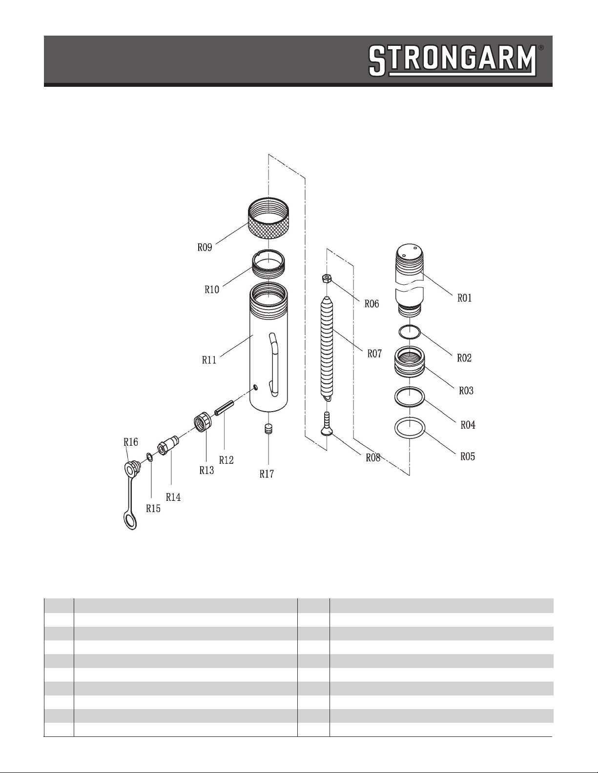
REF PART NUMBER DESCRIPTION REQ REF PART NUMBER DESCRIPTION REQ
RO1 PCN-BRK20SHD-R01 PISTON ROD 1R10 PCN-BRK20SHD-R10 LIMITED RING 1
R02 PCN-BRK20SHD-R02 O-RING 1R11 PCN-BRK20SHD-R11 RAM 1
R03 PCN-BRK20SHD-R03 PISTON 1R12 PCN-BRK20SHD-R12 PIN 1
R04 PCN-BRK20SHD-R04 WASHER 1R13 PCN-BRK20SHD-R14A CONNECTOR ASSY 1
R05 PCN-BRK20SHD-R05 O-RING 1R14 PCN-BRK20SHD-R14A CONNECTOR ASSY 1
R06 PCN-BRK20SHD-R06 NUT 1R15 PCN-BRK20SHD-R14A CONNECTOR ASSY 1
R07 PCN-BRK20SHD-R07 SPRING 1R16 PCN-BRK20SHD-R14A CONNECTOR ASSY 1
R08 PCN-BRK20SHD-R08 SCREW 1R17 PCN-BRK-20SHD-R17 SCREW 1
R09 PCN-BRK20SHD-R09 RAM COVER 1
20T BODY REPAIR KIT SHD
PROD. NO. 030256
MOD. NO. BRK-20SHD

surewerx.com
8
This manual suits for next models
1
Table of contents
Other Surewerx Protection Device manuals


Popular Protection Device manuals by other brands


DELTA PLUS
DELTA PLUS SIERRA2 quick start guide

i4Technology
i4Technology Dog STOP Flash + user manual

Blue Giant
Blue Giant MDC6620M Installation & owner's manual

SK
SK MEGAPOD SA17-SK User instruction manual

MAGNA LENS
MAGNA LENS Eye/Ear Safety System quick start guide

Euroflex
Euroflex SPRINGLIGHT HCXS49 operating instructions