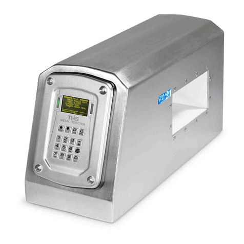
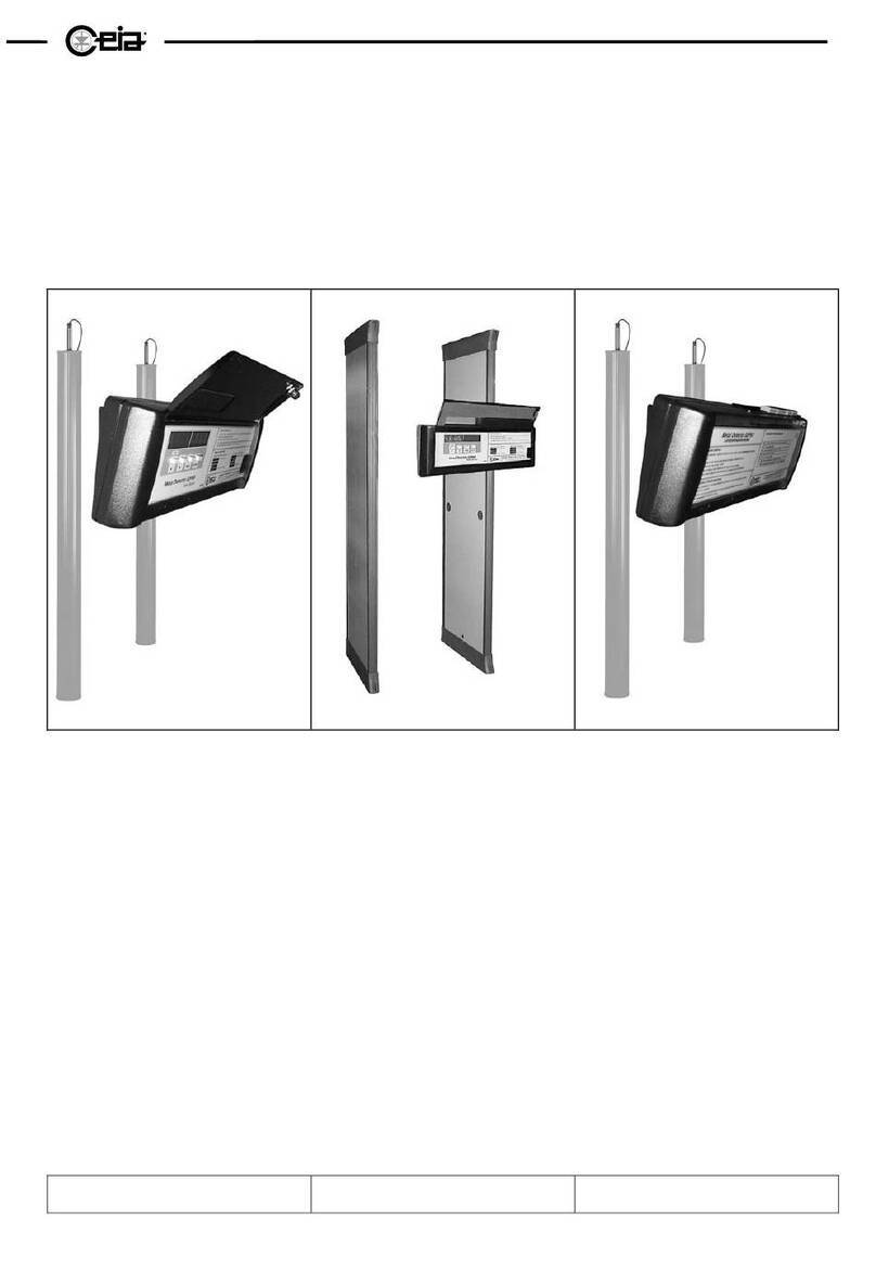
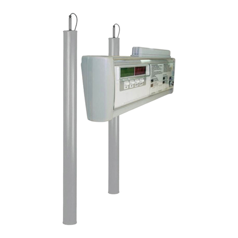
Ceia THS/21E Reference manual

FI002K0018v1530hUK – THS/21 Instruction manual for installation, use and maintenance UK
ORIGINAL INSTRUCTION 1
Industrial Metal Detectors
and Integrated Systems with Conveyor Belt
THS/21E - THS/21
Instruction manual
for installation, use
and maintenance
Document Date Hardware Software
FI002K0018v1530hUK 29/07/2020 HV5.xx THSV5744
ALMV5430 / ALMV5730
Read this manual carefully before installing, operating or carrying out maintenance on the device. Keep the manual in a
safe place for future reference and in perfect condition. This manual must accompany the device described herein in the
case of change of ownership and until the device is decommissioned.

FI002K0018v1530hUK – THS/21 Instruction manual for installation, use and maintenance
2 ORIGINAL INSTRUCTION
SYMBOLS
The equipment is marked with this symbol wherever the user should refer to this manual in order to avoid possible
damage. The same symbol appears in the manual at points where warnings or particularly important instructions,
essential for safe, correct operation of the device, are given.
The equipment is marked with this symbol in the areas where there is dangerous voltage. Only trained maintenance
personnel should carry out work in these areas. The same symbol appears in the manual at points where essential
safety warnings are given.
The equipment is marked with this symbol in the areas where the user must be careful to avoid crushing of hands. Only
trained maintenance personnel should carry out work in these areas. The same symbol appears in the manual at points
where essential safety warnings are given.
The equipment is marked with this symbol in the areas where the user must be careful to avoid coming into contact with
moving components. Only trained maintenance personnel should carry out work in these areas. The same symbol
appears in the manual at points where essential safety warnings are given.
The equipment is marked with this symbol in the areas where the user must be careful to avoid crushing of feet. Only
trained maintenance personnel should carry out work in these areas. The same symbol appears in the manual at points
where essential safety warnings are given.
The equipment is marked with this symbol in the areas where there is the danger of unexpected bursts of compressed
air. Only trained maintenance personnel should carry out work in these areas. The same symbol appears in the manual
at points where essential safety warnings are given.
LASER LIGHT: This symbol appears in this manual at those points where warnings or information relating to laser
pointing devices are given. Such devices may be dangerous. Do not look into the laser beam!
The equipment is marked with this symbol in those areas where insertion of hands, other body parts or objects, is not
permitted, in order to avoid system malfunctions or dangerous situations.
The equipment is marked with this symbol in the areas where it is forbidden to extinguish a fire with water.
CEIA Metal Detectors employ low intensity electromagnetic fields in compliance with current legislation.
MAGNETIC FIELDS can affect pacemakers. Persons wearing pacemakers, cardiac defibrillators and other life support
devices must not operate less than 50 cm from the opening of the Metal Detector tunnel. Wearers of pacemakers must
not operate less than 1 meter from the Metal Detectors of the THS/MN21 series which use static electromagnetic fields.
Persons wearing pacemakers who may need to approach this equipment should consult their medical practitioner
beforehand.
The equipment is marked with this symbol in those areas where it is possible to perform a ground connection.
The equipment is marked with this pictogram in those places where the user is advised to refer to this instruction manual
before any operation.
This symbol appears in the manual at points where suggestions, additional information or other relevant notes are given.

FI002K0018v1530hUK – THS/21 Instruction manual for installation, use and maintenance UK
ORIGINAL INSTRUCTION 3
CONTENTS
1SAFETY INSTRUCTIONS – WARNINGS ....... 9
2DESCRIPTION ............................................... 10
2.1General description................................. 10
2.1.1Metal Detector .......................................... 10
2.1.2Integrated System on conveyor belt ......... 11
2.1.3Products that can be inspected ................ 11
2.2Metal detector ......................................... 12
2.2.1THS/21E and THS/21E-3F ....................... 12
2.2.2THS/21 and THS/MS21............................ 12
2.2.3THS/MN21................................................ 13
2.2.4THS/G21E ................................................ 13
2.2.5THS/G21 and THS/GMS21 ...................... 13
2.2.6Applicable power supply boxes ................ 14
2.2.6.1Control Power Box .................... 14
2.2.6.2Conveyor Control System ......... 15
2.2.6.3Small Size Power Supply Unit ... 15
2.2.6.4Field Generator.......................... 15
2.2.7Other options............................................ 15
2.2.7.1Remote Control Unit .................. 15
2.2.7.2Network card ............................. 15
2.3Integrated system with conveyor belt ..... 16
2.3.1Inverting component positions.................. 17
2.3.1.1Inverting the transit direction............... 17
2.3.1.2Inverting the ejection system position . 17
2.3.2Models...................................................... 18
2.3.2.1THS-FBB (flat belt).............................. 18
2.3.2.2THS-FBBV (flat belt) ........................... 20
2.3.2.3THS-MBB (modular belt)..................... 22
2.3.2.4THS-MBR (modular belt) .................... 24
2.3.2.5THS-FBV (flat belt).............................. 26
2.3.2.6THS-RB and THS-RBK....................... 28
2.4Device identification................................ 29
2.4.1Detection Probe........................................ 29
2.4.2Control Power Box .......................... 29
2.4.3Conveyor Control System ............... 29
2.4.4CEIA conveyor structure........................... 30
2.5Functional diagrams ............................... 30
2.5.1THS with Control Power Box .................... 30
2.5.2THS with Conveyor Control System ......... 31
2.5.3Integrated systems with Conveyor Belt .... 31
2.5.4THS-RB and THS-RBK ............................ 32
2.6Dimensions ............................................. 33
2.6.1Detection Probes ...................................... 33
2.6.1.1THS/21, THS/MS21, THS/21E,
THS/21E-3F........................................ 33
2.6.1.2THS/SL21, THSSL21E ....................... 34
2.6.1.3THS/MN21 .......................................... 34
2.6.1.4THS/G21, THS/GMS21, THS/G21E ... 35
2.6.1.5THS/G21-F, THS/GMS21-F,
THS/G21E-F ....................................... 36
2.6.2Power supply units ................................... 37
2.6.2.1Control Power Box and Field
Generator .................................. 37
2.6.2.2Control Power Box with
Remote Control Unit (THS/21E) ......... 37
2.6.2.3Control Power Box with
Remote Control Unit (THS/21) ........... 38
2.6.2.4Conveyor Control System ......... 38
2.6.2.5Small size power supply unit ..... 38
2.6.3Remote Control Unit ...................... 39
2.6.3.121E series .......................................... 39
2.6.3.221 series............................................. 39
2.6.4Integrated systems................................... 40
2.6.4.1THS-FBB ............................................ 40
2.6.4.2THS-FBBV.......................................... 42
2.6.4.3THS-FBV ............................................ 42
2.6.4.4THS-MBB ........................................... 43
2.6.4.5THS-MBR ........................................... 46
2.6.4.6THS-RB and THS-RBK ...................... 47
2.7Options and Accessories........................ 47
2.8Technical characteristics ........................ 48
2.8.1Metal Detector.......................................... 48
2.8.2Integrated systems................................... 50
3INSTALLATION ............................................. 52
3.1Minimum requirements ........................... 52
3.1.1Minimum installation clearance ................ 52
3.1.1.1Detection Probes................................ 52
3.1.1.2Integrated systems ............................. 52
3.1.2General guidelines for mechanical
installation ................................................ 53
3.1.2.1Controls and Power Supply box ......... 53
3.1.2.2Metal structures in proximity to the
Probe.................................................. 54
3.1.2.3Load-bearing structure ....................... 56
3.1.2.4Conveyor belt and position inside the
Probe.................................................. 57
3.1.2.5Synchronization photocell................... 59
3.1.2.6Metallic flanges................................... 59
3.1.2.8Ejection area ...................................... 60
3.1.3Electrical installation general rules for a
correct compatibility ................................. 61
3.1.3.1Power supply of other devices............ 61
3.1.3.2Signal cables ...................................... 62
3.1.3.3Pulsed-type noise sources ................. 62
3.1.3.4Ground loops prevention .................... 63
3.1.3.5Conveyor belt motors ......................... 64
3.1.3.6Selecting and installing connecting
cables................................................. 65
3.1.3.7Multiple Metal Detectors close
together .............................................. 65
3.2Unpacking............................................... 66
3.2.1Metal Detector.......................................... 66
3.2.1.1Handling and moving the packaged
device................................................. 66
3.2.1.2Unpacking procedure ......................... 66
3.2.1.3Packing list ......................................... 67
3.2.1.4Moving the Metal Detector.................. 67
3.2.2CEIA Integrated Systems......................... 68

FI002K0018v1530hUK – THS/21 Instruction manual for installation, use and maintenance
4 ORIGINAL INSTRUCTION
3.2.2.1Handling and moving the package
device ................................................. 68
3.2.2.2Unpacking procedure ......................... 68
3.2.2.3Packing list ......................................... 69
3.2.2.4Moving the Metal Detector.................. 69
3.2.3THS-RB.................................................... 69
3.2.3.1Handling and moving the package
device ................................................. 69
3.2.3.2Unpacking procedure ......................... 70
3.2.3.3Packing list ......................................... 70
3.2.3.4Moving the Metal Detector.................. 70
3.3Mechanical installation............................ 71
3.3.1Probe ....................................................... 71
3.3.1.1THS Models........................................ 71
3.3.1.2THS/G models.................................... 71
3.3.2Power supply unit..................................... 72
3.3.3Integrated systems................................... 73
3.3.3.1External signalling unit (beacon)......... 73
3.4Pneumatic installation ............................. 73
3.4.1Minimum requirements............................. 73
3.4.2Pneumatic circuit diagrams ...................... 74
3.4.2.1Ejector cylinder................................... 74
3.4.2.2Air jet ejection system......................... 74
3.4.2.3Ejector cylinder................................... 74
3.4.3Connecting up to the compressed air
supply....................................................... 75
3.4.3.1Ejector cylinder................................... 75
3.4.3.2Air jet ejector ...................................... 75
3.4.3.3Retracting belt .................................... 75
3.4.4Pressure adjustment ................................ 76
3.4.5Flow adjustment ....................................... 77
3.4.5.1Ejector cylinder................................... 77
3.4.5.2Air jet ejector ...................................... 78
3.4.5.3Retracting belt .................................... 78
3.4.6Padlocking the compressed air ................ 79
3.5Electrical Installation ............................... 79
3.5.1Installing connecting cables ..................... 79
3.5.2Description of inputs................................. 80
3.5.3Description of outputs .............................. 81
3.5.4Description of I/O interfaces..................... 82
3.5.5Connection of the CEIA Conveyor belt
Emergency circuit..................................... 83
3.5.6Connecting to the mains power supply .... 85
3.5.6.1Connection to earth ............................ 86
3.5.6.2Power Switch...................................... 86
3.6Electrical diagrams.................................. 87
3.6.1Functional diagrams................................. 87
3.6.1.1Control Power Box .................... 87
3.6.1.2Conveyor Control System ......... 88
3.6.2Power Supply units .................................. 89
3.6.2.1Control Power Box .................... 89
3.6.2.2Small Size Power Supply ................... 91
3.6.2.3Field Generator for THS/MN21 . 92
3.6.2.4Conveyor Control System –
ALM card ............................................ 94
3.6.3SCD card ................................................. 98
3.6.3.1THS/xx21E ......................................... 98
3.6.3.2THS/xx21E-3F ....................................99
3.6.3.3THS/xx21 ..........................................100
3.6.3.4THS/xxMS21.....................................101
3.6.3.5THS/MN21 ........................................102
3.6.3.6Input for speed control through a 0-
10V analogic signal........................... 102
3.6.4IXC card (available on request) .............. 103
3.6.5Integrated Systems.................................104
3.6.5.1THS-FBB, THS-MBB, THS-FBV,
THS-FBBV without SCN board ......... 104
3.6.5.2THS-FBB, THS-MBB, THS-FBV,
THS-FBBV with SCN board .............. 106
3.6.5.3THS-MBR..........................................108
3.7Description of electrical connections .... 110
3.7.100211ALM card ......................................110
3.7.2Settings of SW1 minidip..........................114
3.7.300211AL_ card .......................................114
3.7.4Connection of push-buttons or sensors ..115
3.7.4.1Sensor positioning ............................116
3.7.5Connection of an ejection system...........117
3.7.6Synchronization photocell.......................117
3.7.7Ejection check photocell ......................... 117
3.7.8Connection to other in-line devices or
machines ................................................118
3.8Communication connections ................ 119
3.8.1RS232 Serial port connections ...............119
3.8.2BT Wireless Communication ..................119
3.8.3Ethernet / WiFi connections (on request,
with IXC card) .........................................119
3.9Configuration ........................................ 120
3.9.1System start-up ......................................120
3.9.2Preliminary settings ................................120
3.9.3Checking the input and output
connections ............................................121
3.9.4Motor (only with Conveyor Control
System) ..................................................121
3.9.5Transit speed.......................................... 122
3.9.5.2Application with Conveyor Control
System ..............................................122
3.9.6Encoder ..................................................123
3.9.7Synchronization photocell.......................123
3.9.8Ejection check photocell ......................... 124
3.9.9Ejection mode......................................... 124
3.9.9.1Ejection with manual reset (EM=B) ...125
3.9.9.2Photocell synchronized ejection, with
manual reset (EM=SB)......................126
3.9.9.3Reversing belt (EM=R)...................... 127
3.9.9.4Automatic ejection (EM=F)................128
3.9.9.5Automatic ejection with photocell
synchronization (EM=S).................... 129
3.9.9.6Automatic ejection for high-speed
applications (EM=FS)........................ 131
3.9.10Barcode reader....................................... 133
3.9.10.1With change of Detection Mode or
Band between two products..............133
3.9.10.2Without change of Detection Mode or
Band between two products..............134

FI002K0018v1530hUK – THS/21 Instruction manual for installation, use and maintenance UK
ORIGINAL INSTRUCTION 5
3.10Timing ................................................... 134
3.10.1EM = B ................................................... 135
3.10.2EM = SB ................................................. 136
3.10.3EM = R ................................................... 137
3.10.4EM = F.................................................... 137
3.10.5EM = S ................................................... 138
3.10.6EM = FS ................................................. 139
3.11Enabling from and to external machines140
3.11.1Metal Detector inhibition ......................... 140
3.11.2Forcing of the ejection cycle ................... 140
3.11.3Enabling from an in-line device (i.e.
downstream belt).................................... 141
3.11.4Enabling an in-line device (i.e. upstream
belt) ........................................................ 142
3.12Checking the correct installation and
configuration ......................................... 143
3.13Settings for CFR21 Standards.............. 144
3.13.1General information ................................ 144
3.13.2Metal Detector settings requirements ..... 144
3.13.3Digital Signature verification ................... 145
3.13.3.1Through the web site ........................ 145
3.13.3.2Through CEIA THS Production......... 145
4USE OF THE DEVICE.................................. 146
4.1Indicators .............................................. 146
4.1.1Optical indicators .................................... 146
4.1.1.1Control panel .................................... 146
4.1.1.2Conveyor Control System ................. 146
4.1.1.3External beacon................................ 147
4.1.2Acoustic indicators.................................. 147
4.1.3Operator positions .................................. 147
4.2Controls................................................. 148
4.2.1Control Panel.......................................... 148
4.2.2Conveyor Control System power supply
unit control panel .................................... 149
4.3Switching on the Metal Detector ........... 150
4.3.1Checking the safety features .................. 150
4.3.1.1Checking emergency devices ........... 151
4.3.2Switching on ........................................... 151
4.3.3Signals at power-up................................ 152
4.3.4Signals given during normal operation ... 153
4.3.4.1Indication of the received signal........ 153
4.3.4.2Display messages............................. 154
4.3.5Signals given during self-diagnosis ........ 155
4.3.6Other signalizations ................................ 155
4.4Use of the device .................................. 156
4.4.1Loading the product to be inspected....... 156
4.4.2Starting/stopping the conveyor
belt.......................................................... 156
4.4.3Adjustment of the belt speed ........ 157
4.4.4Automatic stop.............................. 157
4.4.5Emergency stop............................ 158
4.4.6Alarm reset..............................................158
4.4.7Fault reset ...............................................158
4.4.8Removing and emptying the reject bin ....159
4.4.8.1THS-FBB, THS-MBB, THS-FBV and
THS-FBBV.........................................159
4.4.8.2THS-MBR ..........................................159
4.5Programming access............................ 160
4.5.1Password modification ............................160
4.6Product selection .................................. 161
4.7Programming the Metal Detector
according to the product type ............... 161
4.8Sensitivity check with reference sample162
4.8.1Performing tests......................................162
4.8.1.1Performing a Test in standard mode .163
4.8.2Performing a Quick test...........................165
4.8.3Performing an automatic test ..................166
4.8.3.1Automatic test sequence ...................166
5MAINTENANCE........................................... 168
5.1Periodic Maintenance ........................... 168
5.2Periodic Maintenance procedures........ 169
5.2.1External cleaning instructions .................169
5.2.2Cleaning instructions for the parts in
contact with the product ..........................169
5.2.3Disassembly of the Conveyor belt...........170
5.2.3.1THS-FBB ...........................................171
5.2.3.2THS-FBV ...........................................172
5.2.3.3THS-MBB and THS-MBR ..................175
5.2.3.4THS-RB .............................................176
5.2.4Conveyor belt tension and centering
adjustment ..............................................177
5.2.4.1THS-FBB ...........................................177
5.2.4.2THS-FBV ...........................................177
5.3Troubleshooting.................................... 178
5.4Extraordinary maintenance procedures 181
5.4.1Changing fuses .......................................181
5.4.2Replacing the SCD card..........................182
5.5Electromagnetic compatibility
verification of the installation
environment.......................................... 185
5.5.1General compatibility check ....................186
5.5.2Electrical Compatibility check..................186
5.5.3Compatibility checks result......................187
5.5.3.1Corrective actions..............................187
5.5.4Checking belt contamination ...................188
5.6Self-diagnosis ....................................... 189
5.6.1Metal Detector and integrated transport
system diagnosis ....................................190
5.6.2Connected sensors and additional
controls diagnosis ...................................193
5.6.3Warning messages .................................198
5.7Uninstallation procedure....................... 199
5.7.1Disassembly............................................199
5.7.2Packing ...................................................199

FI002K0018v1530hUK – THS/21 Instruction manual for installation, use and maintenance
6 ORIGINAL INSTRUCTION
5.7.2.1Probes .............................................. 199
5.7.2.2Integrated systems ........................... 200
5.8Disposal of the device........................... 201
5.8.1Disposal of the device and of
consumables with environmental impact 201
6APPENDICES .............................................. 203
6.1CE Declaration of Conformity ............... 203
6.1.1THS/21E ................................................ 203
6.1.2THS/21 ................................................... 204
6.1.3THS/G21................................................. 205
6.1.4THS/G21E ..............................................206
6.1.5THS/GMS21 ...........................................207
6.1.6THS/MS21 .............................................. 208
6.1.7THS/MN21..............................................209
6.1.8THS-FBB, THS-MBB, THS-MBR, THS-
FBV and THS-RB ...................................210
6.2Spare Parts........................................... 210

FI002K0018v1530hUK – THS/21 Instruction manual for installation, use and maintenance UK
ORIGINAL INSTRUCTION 7
Warranty terms
The warranty period on all CEIA products is 12 months from the date of delivery. The warranty
applies to all products supplied by us. The warranty covers defects of all components excluding
batteries. The warranty does not cover damage caused by improper or inappropriate use or use
for purposes other than those described in this manual. Do not tamper with the device. Do not
open the housing. Tampering with or opening the device will void the warranty.
Customer Satisfaction feedback form
CEIA operates a policy of continuous improvement to guarantee the maximum quality of its
products and services. Your suggestions and comments about our products and services are
an important part of the improvement process and we would be grateful if you could
complete the Customer Satisfaction form on the CEIA website at:
http://www.ceia.net/industrial/satisfaction
CEIA reserves the right to make changes to the content and systems described in this manual, at any time and
without prior notice. Indications of sizes and designs of Systems, therefore, have no binding character, but are given
for information purposes only.
REVISION HISTORY
Rev.
Date
Author
Reference
Description
1000 2010-09-16 TP2 – SP - First issue for all THS/21E and THS/21 models
1100 2012-03-29 TP2 – SP
- Small corrections
- Management of external emergency buttons and
other protections
2.8.2, 3.1.3, 4.5.6, 5.1
A
dditional indications on bins and respect for the
environment
1110 2012-06-26 TP2
–
SP 6.1 CE Certificates updated
1200 2013-09-26 TP2
–
SP - Software updated to THSV5412
1210 2014-03-03 TP2 – SP
- Added MN21 on THS-FBB
- Removed THS-FB, THS/M65, THS/M69K models
3.3.2
A
dded installation warning for Integrated Systems
2.6.4.2 Modified available dimensions for THS-MBB
1220 2015-01-13 TP2
–
SP - Software updated to THSV5432
–
A
LMV5420
1300 2015-12-16 TP2
–
SP - Software updated to THSV5436
–
A
dded THS-RB
1310 2016-01-21 TP2
–
SP 3.8.3
A
dded diagram
1400 2016-05-16 TP2 – SP 3.5.7.1, 3.6 Electrical diagrams updated
2.6.1.5, 3.3.1
A
dditional indications
1410 2016-12-21 TP2 – SP
3.5.3 Small correction
3.6
A
dded electrical diagrams
6.1 CE Certificates updated
1411 2017-06-27 TP2
–
SP - Small corrections
1490 2019-03-28 TP2 – SP - Software updated to THSV5441
–
A
LMV5430 and
THSV5741 – ALMV5730
1500 2019-04-02 TP2
–
SP -
A
dditional corrections
1510 2019-07-20 DTP
–
SP - Small corrections
1520 2020-05-26 DTP
–
SF 6.1 CE Certificates updated
1530 2020-07-29 DTP
–
SF 4.8.3
A
utomatic test procedure

FI002K0018v1530hUK – THS/21 Instruction manual for installation, use and maintenance
8 ORIGINAL INSTRUCTION
Preface
This document is the property of CEIA S.p.A. which reserves all rights. Total or partial copying,
modification and translation is forbidden.
CEIA reserves the right to make changes, at any time and without notice, to the models (including
programming), their accessories and options, and to the prices and conditions of sale.
The Metal Detector or the CEIA integrated system must be used only for the prescribed purpose and
in the ways described in this Manual. CEIA may not be held responsible for the consequences
resulting from a use other than that indicated in this Manual.
Purpose of the documentation
The complete documentation for a CEIA Metal Detector is made up of a series of Manuals, whose
purposes are listed in the following paragraphs:
Warnings manual
The safety instructions specify the safety precautions to be implemented when installing and
operating CEIA products. These instructions must be implemented throughout the life cycle of the
product.
Installation, Use and Maintenance Manual
The purpose of the Installation, Use and Maintenance Manual is to provide the information needed
for:
- installing the Metal Detector or CEIA integrated system, according to the electrical and
mechanical requirements specified by CEIA;
- configuring the Metal Detector in accordance with the type of installation and use;
- correct use of the conveyor belt system;
- correct maintenance, both ordinary and extraordinary.
Programming Manual
The purpose of the Programming Manual is to provide a description of all the items of the System
Programming Menu to:
- define the users authorized to operate the System;
- program the Metal Detector in accordance with the type of product to be inspected;
- make remote connections with the Metal Detector, using the available communication
interfaces.
Operator Manual
The purpose of the Operator Manual is to provide all the information needed by the operator for daily
use of the system.
Options, Accessories and Spare Parts List
The purpose of this document is to provide a quick consultation table for ordering any spare parts,
options and accessories.

FI002K0018v1530hUK – THS/21 Instruction manual for installation, use and maintenance 1
SAFETY INSTRUCTIONS -
W
ARNINGS
ORIGINAL INSTRUCTION 9
1SAFETY INSTRUCTIONS – WARNINGS
All Safety Instructions and Warnings are reported on the proper Warnings Manual that shall be
carefully read before any installation, use or maintenance operation on the device.

2 FI002K0018v1530hUK – THS/21 Instruction manual for installation, use and maintenance
DESCRIPTION
10 ORIGINAL INSTRUCTION
2DESCRIPTION
2.1 General description
CEIA THS inspection systems detect metals with high detection sensitivity, for industrial use in
inspecting food or other compatible products (see paragraph 2.1.3). They are available in two
versions:
- Metal Detector: Detection Probe with power supply unit
- Integrated system: Metal Detector integrated on a conveyor belt system
2.1.1 Metal Detector
This system is designed for installation on a production line suitably set up by the customer or the
installer. It consists of a Detection Probe and a Power Supply Unit only.
The Detection Probe generates an electromagnetic field and receive, at the same time, a signal
produced by the variation of the field itself, upon interaction with metal fragments, contained in the
product to be inspected, in transit through the tunnel.
Some products, according to their own chemical-phisical characteristics, may presents magnetic and
/ or electrical properties such as to also interact with the generated field, determining a signal called
“product effect”: in this case, the Metal Detector allow to perform an automatic procedure to record
the product characteristics, in order to minimize the effect and, at the same time, to set the optimal
threshold for the discrimination of the signal due to metal, with the consequential signals to all devices
connected to the Metal Detector.
The level of a signal produced by a metallic fragment depends on the metal kind, on its dimensions
and volume, and may vary according to its orientation during the transit through the tunnel: therefore
CEIA, according to the model and to the product type, supply proper metallic samples which the
spherical geometry and type are certified to guarantee the maximum repeatibility on Metal Detector
performance evaluation.
All models are available in two different subclasses, the 21E Series and the 21 Series, with different
features and characteristics, as stated below:
Features 21E Series 21 Series
Display type Alphanumeric OLED
4x20 characters
Graphic OLED
128x64 pixels
Local Programming: for commands selection, parameters modification
and alphanumeric data entry
4 keys
3 with double
function
16 keys
3 with double
function
Quick Access function:
for quick selection of most frequently used functions No Yes
Autotest function: for the continuous monitoring and optimization of the
Metal Detector detection features No Yes
Automatic detection performance evaluation: for the evaluation of
detectable CEIA test samples, according to the Metal Detector current
setup
No Yes
Sensitivity High Very High
Product memories: to save all detection parameters for different
products to be inspected 250 500
Event log: recording of all Metal Detector alarms, diagnostic messages
and programming actions 1000 10000
Detection technology 3F Technology Multi Spectrum
Technology
Protection degree IP65 IP66 and IP69K

FI002K0018v1530hUK – THS/21 Instruction manual for installation, use and maintenance 2
DESCRIPTION
ORIGINAL INSTRUCTION 11
2.1.2 Integrated System on conveyor belt
With this version the CEIA THS Metal Detector is fully housed in a high-hygiene, stainless steel
structure fitted with a digital controller for controlling speed and the ejection stages for non-
conforming product.
CEIA inspections systems are available in a wide range of sizes suitable for a wide variety of
applications. The casing structure, the Metal Detector and the belt control panel are all made from
stainless steel.
The conveyor belt, the fully moulded cover for the ejection area and the reject product container are
all fully certified for food-safe applications.
2.1.3 Products that can be inspected
Parts of the Metal Detector and CEIA integrated systems which come in contact with product are
made from FDA certified materials, for full compatibility with food products.
The characteristics of the materials used can be provided by CEIA on request.
Products that can be inspected
- with dimensions and weight compatible with the useful opening of the Detection Probe and
the characteristics of the transport system;
- with chemical-physical characteristics compatible with the parts of the System that come in
contact with the product;
- with chemical-physical characteristics compatible with the metal detection performances
achievable by the System.
Products that can NOT be inspected
- all those which do not comply with even one of the points listed above.

2 FI002K0018v1530hUK – THS/21 Instruction manual for installation, use and maintenance
DESCRIPTION
12 ORIGINAL INSTRUCTION
2.2 Metal detector
2.2.1 THS/21E and THS/21E-3F
The THS/21E is a high-sensitivity Metal Detector controlled by a microprocessor and designed for
industrial use. It is also available in an extremely compact version, the THS/SL21E (SLIM LINE
version), for mounting on a conveyor belt and is ideal for weighing machines.
The THS/21E-3F is a multi-frequency technology model, for use with a variety of products with
significant chemical-physical differences (dry, wet, frozen product, packed in metallized film). A slim
line version is also available: THS/SL21E-3F.
THS/21E
A The Metal Detector Probe, complete with electronic control
unit (SCD)
B The power supply box, for connecting the device to mains
power and to the external units (photocell, ejector, etc.).
C Connecting cable
D Tunnel
E Stainless steel control panel fitted with alphanumeric display
and a 4-key programming keyboard
2.2.2 THS/21 and THS/MS21
The THS/21 is a very high-sensitivity Metal Detector controlled by a microprocessor and designed
for industrial applications processing dry products. It is also available in an extremely compact
version, the THS/SL21 (SLIM LINE version), for mounting on a conveyor belt and is ideal for weighing
machines.
The THS/MS21 is a multi-spectrum technology model, for use with a variety of products with
significant chemical-physical differences (dry, wet, frozen product, packed in metallized film). A slim
line version is also available: THS/SLMS21.
THS/21
A The Metal Detector Probe, complete with electronic control
unit (SCD)
B The power supply box, for connecting the device to mains
power and to the external units (photocell, ejector, etc.).
C Connecting cable
D Tunnel
E Stainless steel control panel fitted with graphic display and a
16-key programming keyboard

FI002K0018v1530hUK – THS/21 Instruction manual for installation, use and maintenance 2
DESCRIPTION
ORIGINAL INSTRUCTION 13
2.2.3 THS/MN21
The THS/MN21 is a very-high sensitivity Metal Detector for detecting ferromagnetic metal
contaminants in products inside containers made from non-magnetic metal foil (e.g. aluminium foil)
or inside aluminium trays.
It is also used to detect needles in clothes with non-magnetic accessories (buttons, zips, etc. …).
THS/MN21
A The Metal Detector Probe complete with electronic control unit
(SCD)
B
The Control Power Box, for connecting the device to mains power
and to the external units (photocell, ejector, etc.).
See section 2.3 for all possible configurations.
C Connecting cable
D Tunnel
E Stainless steel control panel, fitted with graphic display and 16-key
programming keyboard
F Field generator
2.2.4 THS/G21E
The THS/G21E is a high-sensitivity model with circular tunnel for products transported in tubing.
The Probe is designed to be fixed in an inaccessible position. The detector controls are therefore
incorporated in the power supply unit.
Its typical use is between multi-head weighing machines and packaging machines, or in gravitational
and pneumatic product transport systems in general (powders, granular material, liquids etc.).
THS/G21E
A The Metal Detector Probe complete with electronic control unit
(SCD)
B
The power supply box, for connecting the device to mains power
and to the external units (photocell, ejector, etc.), with a remote
control unit (RCU).
See section 2.3 for possible configurations.
C Connecting cable
D Tunnel
E Stainless steel control panel, fitted with alphanumeric display and
4-key programming keyboard
2.2.5 THS/G21 and THS/GMS21
The THS/G21 is a very high-sensitivity model with circular tunnel for products transported in tubing.
The Probe is designed to be fixed in an inaccessible position. The detector controls are therefore
incorporated in the power supply unit.
The typical use of THS/G21 is between multi-head weighing machines and packaging machines, or
in gravitational and pneumatic product transport systems for dry products (e.g. powders or granular
material).
The THS/GMS21 is a multi-spectrum model, for use with a variety of products with significant
chemical-physical differences (powders, granular material, liquids etc.).
THS/G21
A The Metal Detector Probe complete with electronic control unit
(SCD)
B
The power supply box, for connecting the device to mains power
and to the external units (photocell, ejector, etc.), with a remote
control unit (RCU).
See section 2.3 for possible configurations.
C Connecting cable
D Tunnel
E Stainless steel control panel, fitted with graphic display and 16-key
programming keyboard

2 FI002K0018v1530hUK – THS/21 Instruction manual for installation, use and maintenance
DESCRIPTION
14 ORIGINAL INSTRUCTION
2.2.6 Applicable power supply boxes
2.2.6.1 Control Power Box
The Control Power Box contains the Metal Detector power supply unit. It has connections for external
sensors and slave devices and can also house the remote control unit (RCU).
Control Power Box Control Power Box with Remote
Control Unit (RCU), with 4-key
keyboard and alphanumeric display
(21E series)
Control Power Box with Remote
Control Unit (RCU), with 16-key
keyboard and graphic display (21
Series)
The basic version and the complete version of the Control Power Box are fitted with an card.
The difference between the two versions is in the type and number of connections for external
devices as detailed in the table below, where all data related to the small-size power supply unit
( card) are also reported:
IN / OUT
card
card
Basic version Complete version
Auxiliary relay (AUX RELAY) OUT
Test request relay (TEST REQUEST RELAY) OUT
Upstream conveyor relay (PREC CONV RELAY) OUT
Ready relay (READY RELAY) OUT
Ejection relay (EJECT RELAY) OUT
Alarm relay (ALARM RELAY) OUT
RS-232 IN / OUT
Barcode Reader IN
Auxiliary RS-232 IN / OUT
RCU connection IN / OUT
Ejector OUT
Following Conveyor IN
Inhibition IN
Bin absent IN
Auxiliary input IN
Ejector position check IN
Ejection check IN
Ejection confirmation IN
Ejection synchronization IN
Reset IN
Low pressure IN
Encoder IN
Bin full IN
External beacon OUT
Emergency circuit IN
BT Wireless Communication IN / OUT
Predisposition for Ethernet/WIFI card IN / OUT

FI002K0018v1530hUK – THS/21 Instruction manual for installation, use and maintenance
2
DESCRIPTION
ORIGINAL INSTRUCTION 15
2.2.6.2 Conveyor Control System
This unit has the same functions as the full version of the control power box
(CPB) and in addition has a conveyor belt motor driver/control section.
This module is available on the following versions:
- CE-mark version 230 V
- USA version 115 V
- USA version 230 V
See section 2.8 for the Technical Characteristics.
The Conveyor Control System also incorporates the main switch, the controls for activating the belt
and the LED indicators needed for operation.
2.2.6.3 Small Size Power Supply Unit
The 00211AL_ card is used in OEM applications, for integration in the
customer's systems.
The card requires a power supply voltage of 24 V (20-30 VDC).
2.2.6.4 Field Generator
This unit is part of the THS/MN21 model and is an additional power supply unit.
It is not available for other models.
2.2.7 Other options
2.2.7.1 Remote Control Unit
The THS/21x Metal Detector can be fitted with an
optional remote control unit (RCU). The RCU is
designed for all those applications where the
Detection Probe and the power supply unit are fitted
in positions which are difficult for the operator to
reach.
2.2.7.2 Network card
This card integrates the network interfaces (Ethernet, WiFi), USB (with the option
of the socket outside the power supply) and the Metal Detector Web Server. It is
connected directly to the power supply card present on or on .

2 FI002K0018v1530hUK – THS/21 Instruction manual for installation, use and maintenance
DESCRIPTION
16 ORIGINAL INSTRUCTION
2.3 Integrated system with conveyor belt
CEIA integrated systems incorporate the THS Metal Detector, a conveyor belt and all the related
accessories (e.g. ejection system, reject collection system, barcode reader) in a single system where
all the components are ready installed and configured.
The integrated systems are available with various types of belt, Metal Detector and accessory and
can therefore be customized to individual requirements and applications.
Model THS-FBB THS-FBBV THS-MBB THS-MBR THS-FBV THS-RB
THS-RBK
Typical product
that can be inspected
In horizontal
packaging,
single row;
or loose
In vertical
packaging,
single row
In horizontal
packaging,
single row;
or loose
In horizontal
packaging,
single or
multiple row;
or loose
In vertical
packaging,
single row
In horizontal
packaging,
single row
Belt type Flat Flat Modular Modular Flat Round belt
Available
ejection
mode
Signalization
relay
Belt stop
Reversing
belt
Reject pusher
cylinder
Reject air jet
Bridge ejector
Retracting
belt
Detection
Probe type
THS/21x
THS/MS21
THS/21E-3F
THS/MN21
Transito
direction
from left
to right
from right
to left
Ejection
direction
Towards
the front
Towards
the back
Speed
(m/min)
8 ÷ 40
10 ÷ 35
10 ÷ 55
14 ÷ 60
20 ÷ 80
: Standard - : Available on request - : Available on request, only on some configurations
: Not available - : Only SL version - : Only with belt length of 2000 mm
For details of customized versions with different dimensions and configurations, contact our Sales
Department.

FI002K0018v1530hUK – THS/21 Instruction manual for installation, use and maintenance 2
DESCRIPTION
ORIGINAL INSTRUCTION 17
2.3.1 Inverting component positions
2.3.1.1 Inverting the transit direction
It is possible, as an option at the order stage, to invert the transit direction, with respect to the
Detection Probe Control Panel.
From left to right
From right to left
Example with a THS-FBB
2.3.1.2 Inverting the ejection system position
It is also possible, as an option at the order stage, to invert the position of the ejection system as
shown in the figure below.
Ejection toward the front
Ejection toward the back
Example with a THS-FBB

2 FI002K0018v1530hUK – THS/21 Instruction manual for installation, use and maintenance
DESCRIPTION
18 ORIGINAL INSTRUCTION
2.3.2 Models
2.3.2.1 THS-FBB (flat belt)
THS-FBB with ejection system
A Metal Detector Probe
B Programming and control panel
C Main switch
D Conveyor belt control panel
E Synchronization photocell
F External beacon
G Emergency button
H Reject bin
K Rejected product bin lock (or, upon
request, solenoid lock)
L Ejection system
M
Support feet (to be fixed to the floor)
or
lockable castors
N Ejection Verification photocell
(optional)
O Ejection Confirmation photocell
P Ejection area protection cover
S Bin full sensor (optional)
W Door with magnetic safety sensor
(optional)

FI002K0018v1530hUK – THS/21 Instruction manual for installation, use and maintenance 2
DESCRIPTION
ORIGINAL INSTRUCTION 19
Available features and options
THS-FBB Belt length (BL) 1000 1300 1500 1800 2000*
F Signalling lamp
- Belt type polyurethane (PU) white
high contrast blue
M Stand type adjustable feet (±75mm)
lockable castors (±50mm)
M Belt height extension (only with feet) 75 mm
125 mm
- Side panels for product containment
L Ejection system type
belt stop
reversing belt
reject pusher cylinder
reject air jet
bridge ejector (bidirectional upon request)
H Reject bin
standard size (400mm product input width)
large size (650mm product input width)
double bin (standard or large)
rollers with cover
double rollers with cover
P Output cover
standard (only ejection area)
Extended (until belt end)
with inspection door and Emergency sensor
E Synchronization photocell retro-reflection
retro-reflection, laser
- Ejection confirmation photocell retro-reflection
retro-reflection, barrier
- Additional Sensors kit
Bin full, Low air pressure
Electrick lock for Bin open/absent
Electrick lock with Emergency Stop function
- Encoder
- Ejection verification photocell retro-reflection
retro-reflection, laser
- Shutters for sensors functional verification
Available only on some models of standard systems, without height extensions
Optional, only with bridge ejector
Only with Probe height DH
275
Only on models with ejection system
Only on models with additional sensors kit
Only on belt width BW
400
Standard
Optional accessory
Not available
* Only with THS/MN21 Probe

2 FI002K0018v1530hUK – THS/21 Instruction manual for installation, use and maintenance
DESCRIPTION
20 ORIGINAL INSTRUCTION
2.3.2.2 THS-FBBV (flat belt)
THS-FBBV with ejection system
A Metal Detector Probe
B Programming and control panel
C Main switch
D Conveyor belt control panel
E Synchronization photocell
F External beacon
G Emergency button
H Reject bin
K Rejected product bin lock (or, upon
request, solenoid lock)
L Ejection system
M
Support feet (to be fixed to the floor)
or
lockable castors
N Ejection Verification photocell
(optional)
O Ejection Confirmation photocell
P Ejection area protection cover
R Product containment banks
S Bin full sensor (optional)
Other manuals for THS/21E
2
This manual suits for next models
1
Table of contents
Other Ceia Metal Detector manuals