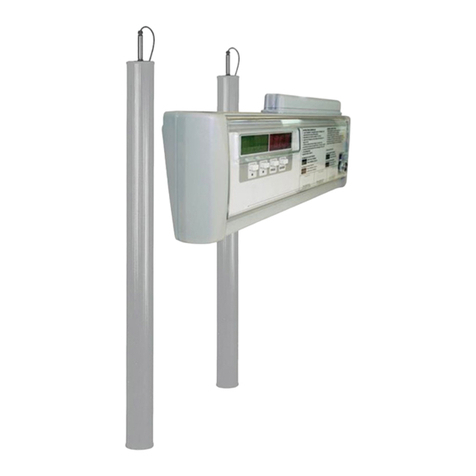
Ceia 02PN8 HI-PE/CN-AS-140 Instruction Manual

02PN8 HI-PE - 02PN7 --- Rev. FI 002 GB 60K10/16 v2_01
1
02PN8 HI-PE/CN-AS 02PN8 HI-PE/PN-AS-600 02PN7
METAL DETECTORS
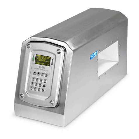
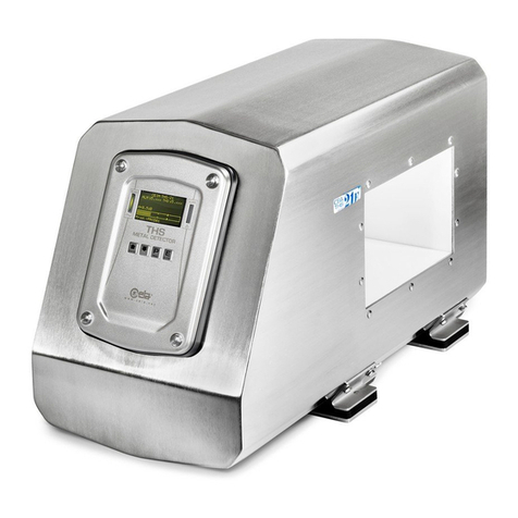
02PN8 HI-PE/CN-AS-140
02PN8 HI-PE/CN-AS-140L
02PN8 HI-PE/PN-AS-600
02PN7
Installation and Maintenance
ATTENTION!
Keep the transducer matched with the electronics unit and the Technical Booklet having the same
serial number.
Program Version:
HI-PE v8_11 , 02PN7 V1_10 Rev.: FI 002 GB 60K10/16 v2_01
Date 2006-11-14

02PN8 HI-PE - 02PN7 --- Rev. FI 002 GB 60K10/16 v2_01
2
ATTENTION!
READ THESE INSTRUCTIONS BEFORE WORKING WITH THE DEVICE
•Read this manual carefully before installing, operating or carrying
out maintenance on the device.Keep this booklet in a safe place
for future reference.
•Follow the instructions contained in this manual for all operations
relating to installation, use and maintenance of the device. CEIA
cannot be held responsible for any damage resulting from
procedures which are not expressly indicated in this manual.
•The final user is responsible for selecting the appropriate
security level/sensitivity for their application. After this
selection has been made, and programming has been
adjusted accordingly, it is also the final user's responsibility
to verify calibration using the test object(s) appropriate to the
level of security selected. Additionally, this test should be
carried out periodically to insure no changes have occurred
in the equipment.
•CEIA can not be held responsible for direct and/or indirect
damage to persons and/or property arising from failure to
observe these instructions
•Whenever there is any suggestion that the level of protection has
been reduced, the device should be taken out of service and
secured against any possibility of unintentional use, and
authorised service technicians should be called.
The level of protection is considered to have been reduced when:
- the device shows visible signs of deterioration;
- the device does not operate correctly;
- the device has been stored for a long period in sub-optimal
conditions;
- the device has suffered severe stress during transport;
- the device has come into contact with liquids.
•Choose the installation site carefully. Avoid placing the device in
locations where it may be directly exposed to sunlight or in places
that are close to sources of heat. In addition, avoid places that are
subject to vibrations, dust, humidity, rain and excessively high or
low temperatures.
•Installation must be carried out by qualified personnel. Given the
dimensions of the device, it is requested that the installation site
be kept clear while work is carried out to facilitate setting it up and
to avoid any harm to third parties.
•When installation is completed the device must be firmly
anchored to the ground, to prevent an accidental blow causing it
to fall with a consequent risk of harm to people in transit or in the
vicinity thereof.
•Handle the device with care and without excessive force during
installation, use and maintenance
•For optimum performance the device should not be subject to
vibrations or accidental movement. All the connecting cables must
be properly fastened down so as to avoid knocks or accidental
damage and to obtain the best results from the device.
•Position the device as far away as possible from sources of
electromagnetic interference such as transformers or motors.
•Before powering up the device, check that the mains power
supply voltage corresponds to the voltage shown on the device's
electrical specifications plaque.
The device should be connected to the mains voltage only after
all the connections required for full installation have been carried
out.
•The device must be connected to a power supply circuit fitted with
a switch or other device which allows the power to be cut off.
•If the device is to be powered via an external autotransformer to
regulate the voltage, ensure that the common terminal of the
autotransformer is connected to the neutral of the power-supply
circuit.
•The power-supply plug must only be inserted into a socket fitted
with an earth/ground connection.
Any break in the safety conductor, either inside or outside the
device, or disconnection of the earth/ground safety terminal, will
render the device dangerous. Intentional cutting or disconnection
is strictly forbidden.
•The device must be disconnected from all power sources before
undergoing any maintenance or cleaning, and before being
moved.
•Always remove the plug by hand when disconnecting the power
supply cable, never by pulling on the cable..
•To prevent damage by lightning, disconnect the power supply
cable during thunderstorms.
•This device contains electrical and electronic components, and
may therefore be susceptible to fire. Do not install in explosive
atmosphere or in contact with inflammable material. Do not use
water or foam in the case of fire when the device is powered up
•Do not wash the device with water, liquid detergents or chemical
substances. Use a slightly moist, non-abrasive cloth for cleaning.
•Important advice regarding any batteries incorporated in the
device. Replacement: use CEIA spare parts or batteries with
equivalent electrical/mechanical characteristics. Do not dispose of
used batteries in general rubbish bins; use public battery
collection facilities as per local regulations, or return them to a
CEIA office. If the equipment is to be disposed of, remove the
batteries and dispose of them separately.
•Read the chapter on “Maintenance” carefully before calling the
service centre.
Whatever the problem, only specialised service personnel
authorised to work with CEIA equipment should be called.
•Any damaged parts of the device should be replaced by original
components only.
•Any maintenance or repair involving the device being opened
while powered should be avoided as far as possible: if this
becomes inevitable, the operation must be carried out only by
qualified personnel who are fully aware of the risks involved.
Symbols
The device is marked with this symbol whenever the operator or the maintenance personnel, in order to
avoid possible damage, have to refer to the present manual. The same symbol appears in the booklet at
points where warnings or particularly important instructions are given - instructions that are vital to a safe
and correct use of the device.
The device is marked with this symbol in those areas where a dangerous amount of voltage is present.
Only specialised maintenance personnel should make adjustments in these areas.
This sign in the manual indicates tips for optimising the device’s performance.
Warranty conditions
The warranty on all CEIA products, extended to the period agreed with the Sales Department, is applicable to goods
supplied from our factory, and for every constituent part thereof, with the exception of the batteries and the card
reader. Any form of tampering with the device, and in particular opening its container, is strictly forbidden and will
invalidate the warranty.

02PN8 HI-PE - 02PN7 --- Rev. FI 002 GB 60K10/16 v2_01
3
Customer Satisfaction Report
Your suggestions and comments on the products and services offered by CEIA and its distribution network
are extremely important for improving our procedures. We would ask you to send them to us by compiling
and returning the form available:
http://www.ceia.net/security/satisfaction.asp.
Thank you for your kind interest and co-operation.
CEIA reserves the right to make changes, at any moment and without notice, to the models (including programming),
their accessories and optionals, to the prices and conditions of sale.
Contents
ATTENTION! READ THESE INSTRUCTIONS BEFORE WORKING WITH THE DEVICE ............................2
SYMBOLS ..........................................................................................................................................................2
WARRANTY CONDITIONS ...............................................................................................................................2
CONTENTS ........................................................................................................................................................3
DESCRIPTION ...................................................................................................................................................5
OPERATING PRINCIPLE.......................................................................................................................................5
Construction of the Metal Detector ..............................................................................................................6
METAL DETECTOR MODELS................................................................................................................................6
02PN7 ..........................................................................................................................................................6
Electronics Unit.........................................................................................................................................6
Table I-A: Antenna 02PN7........................................................................................................................7
02PN7: Accessories .................................................................................................................................7
02PN8 02PN8 HI-PE...................................................................................................................................8
Electronics Unit.........................................................................................................................................8
Antenna.....................................................................................................................................................9
02PN8 HI-PE: Accessories.....................................................................................................................10
INSTALLATION ...............................................................................................................................................11
GENERAL INSTALLATION NOTES ........................................................................................................................11
ELECTROMAGNETIC COMPATIBILITY...................................................................................................................12
Interference of a mechanical nature ..........................................................................................................12
Table II-A . Distances to be maintained between antennae and cabin structure...................................13
Table II-B . Insulating a metal door.........................................................................................................14
Electrical interference.................................................................................................................................15
Inhibition of the Metal Detector...............................................................................................................15
Orientation of the columns......................................................................................................................15
Installation of coupled metal detectors - synchronisation ..........................................................................16
02PN7.....................................................................................................................................................16
02PN8 HI-PE ..........................................................................................................................................16
ASSEMBLY.......................................................................................................................................................17
Mechanical assembly.................................................................................................................................17
Fixing the electronics unit.......................................................................................................................17
Fixing the antenna ..................................................................................................................................17
Table II- 2. Ways of fixing the various types of antenna: some examples.............................................17
Electrical assembly ....................................................................................................................................18
Connecting the electronics unit to the antennae. ...................................................................................18
Power supply connection........................................................................................................................18
02PN8 HI-PE..............................................................................................................................................19
III - 02PN7 METAL DETECTOR – INSTRUCTIONS FOR USE.....................................................................20
SWITCHING ON THE METAL DETECTOR..............................................................................................................20

02PN8 HI-PE - 02PN7 --- Rev. FI 002 GB 60K10/16 v2_01
4
IV - 02PN7 METAL DETECTOR - PROGRAMMING .....................................................................................20
CONNECTION TO CONTROL TERMINAL................................................................................................................20
CONNECTION TO A CONTROL TERMINAL OR PERSONAL COMPUTER......................................................................20
Connection .................................................................................................................................................20
Free access to programming phase (without password)...........................................................................21
Access to the programming phase by means of the password .................................................................21
Execution of commands in remote programming ......................................................................................21
PROGRAMMING OF THE 02PN7 METAL DETECTOR WITH RCU ............................................................................22
Connection .................................................................................................................................................22
RCU commands.........................................................................................................................................22
Free access to programming phase (without password)...........................................................................23
Access to the programming phase by means of the password .................................................................23
Execution of commands from the RCU......................................................................................................23
DESCRIPTION OF THE 02PN7 METAL DETECTOR COMMANDS ..............................................................................24
02PN7 METAL DETECTOR INSTALLATION CHECKS ..............................................................................................25
V - 02PN8 HI-PE METAL DETECTOR – INSTRUCTIONS FOR USE............................................................26
SWITCHING ON THE METAL DETECTOR..............................................................................................................26
02PN8 HI-PE METAL DETECTOR DISPLAY MESSAGES ........................................................................................26
02PN8 HI-PE METAL DETECTOR STAND-BY ......................................................................................................27
VI - 02PN8 HI-PE METAL DETECTOR - PROGRAMMING ...........................................................................28
LOCAL PROGRAMMING......................................................................................................................................28
COMMAND EXECUTION -LOCAL PROGRAMMING .................................................................................................28
Time out..................................................................................................................................................29
DESCRIPTION OF THE 02PN8 HI-PE METAL DETECTOR COMMANDS ...................................................................29
02PN8 HI-PE metal detector reception parameters ..................................................................................29
02PN8 HI-PE metal detector transmission parameters.............................................................................30
02PN8 HI-PE metal detector alarm signal parameters..............................................................................30
02PN8 HI-PE metal detector management ...............................................................................................31
ANALYSIS PROGRAMS AVAILABLE WITH THE COMMAND "IS"......................................................33
02PN8 HI-PE METAL DETECTOR INSTALLATION CHECKS....................................................................................33
MEASUREMENT OF THE QUALITY FACTOR (02PN8 HI-PE metal detector) .......................................35
Measurement of the Quality Factor- Procedure .....................................................................................35
ADVANCED PROGRAMMING-REMOTE PROGRAMMING.........................................................................................36
Serial communication.................................................................................................................................36
Communication system configuration.....................................................................................................37
Free access to programming phase (without password)...........................................................................37
Execution of commands in remote programming ......................................................................................37
Simultaneous access request by remote and local programming.............................................................37
ADVANCED PROGRAMMING: use of the password................................................................................38
Programming levels................................................................................................................................38
Password definition.................................................................................................................................38
Access to the programming phase using the password.........................................................................39
Programming without password .............................................................................................................39
Parameters accessible from remote programming only (02PN8 HI-PE)...................................................40
TECHNICAL CHARACTERISTICS .................................................................................................................41
02PN7............................................................................................................................................................41
02PN8 HI-PE .................................................................................................................................................42
MAINTENANCE ...............................................................................................................................................43
DIAGNOSIS ......................................................................................................................................................43
AUTOTEST PROGRAM .......................................................................................................................................44
TROUBLESHOOTING .........................................................................................................................................45
COMPATIBILITY ASPECTS ..................................................................................................................................46
Column antenna orientation procedure to minimise electrical interference...............................................48
APPENDICES ..................................................................................................................................................49
DECLARATION OF CE CONFORMITY ........................................................................................................49
SPARE PARTS ..................................................................................................................................................50

02PN8 HI-PE - 02PN7 --- Rev. FI 002 GB 60K10/16 v2_01
5
DESCRIPTION
Operating Principle
In general, a modern Metal Detector for checking people in transit comprises:
• An electronics unit, made up of:
• a variable magnetic field
generator
• a receiver
• a processing and control unit,
which determines if the variation
of the received signal is due to
metal masses in transit of a
certain shape, volume or
composition
• a transceiver antenna
comprising a pair of columns or
panels
Field
Generator Receiver
Processing and Control Unit
Transmitter
Antenna Receiver
Antenna
Antenna
Electronics unit
Fig. 1: general block diagram of a metal detector
SOME HELPFUL GUIDELINES FOR METAL DETECTORS
The parameters which best characterise a Metal Detector are
as follows :
• Discrimination:This parameter reflects the variation in
sensitivity between potentially dangerous metal objects
(due to their particular shape compared with their volume)
and personal effects (such as coins, keys, watches,
buckles, etc...). When a detector with low discrimination is
used, personal effects can cause a large number of false
alarms, rendering the system ineffective in practical terms.
• Uniformity in detection efficiency: This parameter is
closely connected with the linearity of the magnetic field
generated inside the Metal Detector. Generally speaking,
the greater the uniformity, the better the discrimination.
• Sensitivity: alarm activation threshold: the greater the
sensitivity, the smaller the metal mass which will cause an
alarm.
• Interception speed: the transit speed of a person through
the metal detector archway usually depends on situational
factors, and can vary considerably. The sensitivity of a
good Metal Detector should be independent of the speed
of transit.
• Programming: C.E.I.A. have designed their Metal
Detectors to include the possibility of selecting the
settings of the operational parameters: this predisposition
facilitates both the installation of the device (rejection of
external sources of interference) and adaptation to the
user’s requirements (orientation towards ferromagnetic
and/or non-magnetic metals). This feature is particularly
important in the detection of weapons made of light metal.
• Immunity to interference: environmental electromagnetic
interference of mechanical or electrical origin is the
principal cause of false alarms, because it augments the
effective signal of the mass to be detected. Particular
attention must therefore be paid to the Metal Detector’s
immunity to this type of interference.
• Harmlessness to life support systems and storage media:
the field emitted by the Metal Detector should be below the
values set by international standards which guarantee
harmlessness to life support systems such as pace-makers,
adrenaline pumps etc. Observance of these limits also
means that there is no effect whatsoever on computer-type
storage media.
• Synchronisation: multiple installations of Metal Detectors are
very common (just think of an airport departure terminal). To
allow several Metal Detectors to operate in a restricted area
without influencing each other, it must be possible to
synchronise them without the help of cable connections.
• Power supply flexibility: wide tolerance range for the input
voltage and emergency batteries which cut in automatically
ensure that the Metal Detector continues operating in the
case of variations or cuts in the mains supply.
•Set-up and calibration with respect to the reference sample:
a modern Metal Detector must allow its installation in
whatever environment, without any interference caused by
other external devices. The security level may usually be
adjusted acting on sensitivity: CEIA’s Metal Detectors are
also provided with a special command (IS) allowing the
direct selection of the functioning parameters which
determine a security level conforming to the International
Standards.
• Maintenance: a modern Metal Detector generally
incorporates a self-diagnosis system which identifies any
sabotage and which also signals accidental faults. Modular
construction furthermore allows the faulty parts to be
replaced quickly and easily, thereby minimising the time the
device is out of operation.

02PN8 HI-PE - 02PN7 --- Rev. FI 002 GB 60K10/16 v2_01
6
Construction of the Metal Detector
The CEIA Metal Detectors described in this manual are most commonly used in airlock-type access cabins.
They are made up of an electronics unit and an archway antenna;
The antenna is constructed in exceptionally strong synthetic material, and in the shapes described in the
following pages. The standard colour is light grey.
Each antenna unit comprises a transmitter and receiver antenna with identification marks (Cin the figures
below), both on the side which faces into the transit passageway and on the electronics unit connecting
cable. The labels are green on the transmitter antenna and red on the receiver. Connection between the
electronics unit and the antennae is via two cables (one for the transmitter and one for the receiver).
Fig. I-2a: identification mark on
panel model Fig. I-2b identification mark on
column model Fig. I-2c: identification mark on
column model with extension
cables
Metal Detector Models
The models described in this manual are as follows:
02PN7
Electronics Unit
The electronics unit, which is extremely compact, is
available in an shock-resistant plastic casing (1) with
protection grade IP20 , designed for wall-mounting.
The 02PN7 model can only accept remote
programming, and its electronics unit does not
therefore have either a display or a keypad. The
connectors/terminal board (2) are freely accessible.
The antenna comprises two cylindrical columns. (see
table I-A).
Fig. I-3: electronics unit 02PN7 in IP 20 container
82
J1 J2 J4J3
32
275
380
135
92
32
144
M6x12
Fig. I-4: dimensions of the 02PN7 electronics unit
c
c
c
1
2

02PN8 HI-PE - 02PN7 --- Rev. FI 002 GB 60K10/16 v2_01
7
Table I-A: Antenna 02PN7
1970
UW
ø25
ø140
PL
Rmin 40
15
15
ø144
ø144
UW |
640 - 760
PL | 40
| 130
| 250
| 280
Fig. I-5a: dimensions of the
antenna: example of model with
options 3 and 4 (see below)
02PN7: Options
Type of cable Anchoring
1
11 max
35 32
168
8000
800
Fig. I-5b: 0.8m cable with connector, with
8m extension
2
11 max
3000
Fig. I-5c: Simple 3m cable
3
ø144
ø22
ø20
11
Fig. I-5d Anchoring without flange: Fixing
via insertion of central conical support
fixed to floor
Top fixing and cable exits
4
25
30
PL
40mm
130mm
250mm
280mm
PL
Fig. I-5e: Fixing via locking of the metal
tube. The cable leads out of the middle of
the tube
5
3
27
Fig. I-5f: Fixing via direct locking of the
column body. Axial cable exit.
6
15
M10
3
Fig. I-5g: Fixing via central screw M10x12.
Off-centre cable exit
02PN7: Accessories
RCU
Fig. I-5h
The RCU, connected to the detector via serial line, allows remote programming. It also
provides audible and light-based alarm signalling with a bar-graph indication
proportional to the metal mass detected.
Dimensions: 217x140x75 mm.
Material included:
Cable C60146, for connecting the RCU to the Metal Detector; sub-D 9 pole connectors
Optional accessories:
C60300 extension, for direct connection to the 02PN7 electronics unit and parallel lines for control button unit.

02PN8 HI-PE - 02PN7 --- Rev. FI 002 GB 60K10/16 v2_01
8
Mains transformer
Fig. I-5k
Mains power-supply transformer, connectable directly to the electronics unit.
Input voltage: 230 V~ or 115V~
Dimensions: 121 x 80 x 71 (LxWxH)
Cable length plug side:: 2m
Cable length electronics unit side: 2m
Protection degree: IP30 (IEC529)
Weight: 1.5 kg.
02PN8 02PN8 HI-PE
Electronics Unit
The electronics unit, which is extremely compact, is available in an shock-resistant plastic casing, with
protection grade IP20, designed for mounting on walls or in other locations proposed by the installer.
The alphanumeric display (3) and the programming keypad (4) are situated at the front, protected by a
transparent panel (1) fitted with a security lock (2). A cover (5) on the top of the unit protects the terminal
board and connectors to which the antenna, power supply, serial and slave connections are made
Fig. 2: 02PN8 HI-PE electronics unit in IP 20 casin
82
M6x12
AA AA A
Fig. I-7: dimensions of the 02PN8 HI-PE electronics unit. A: connecting cable outputs
1
4
2
3 5

02PN8 HI-PE - 02PN7 --- Rev. FI 002 GB 60K10/16 v2_01
9
Antenna
The 02PN8 HI-PE antenna is available in various configurations as described below::
•02PN8 HI-PE/PN-AS-600, panel model
•02PN8 HI-PE/CN-AS-140 , column model
•02PN8 HI-PE/CN-AS-140L , column model with extra-wide passageway
Table I-B: 02PN8 HI-PE/PN-AS-600
UW+110
ø10 L=3000
Rmin 40
50
UW
TH
600
60
629
657
ø6.5
60
UW+ 50
UW | 680-900
TH | 2040
| 2160
| 2172
| 2220
Fig. I-8: dimensions of the
antenna
Options
TX
Fig. I-9a Photocells
RX
Fig. I-9b Reflectors
Transit counter
Two photocells fitted into the
antennae allow counting of transits,
alarms and percentage of alarms.

02PN8 HI-PE - 02PN7 --- Rev. FI 002 GB 60K10/16 v2_01
10
Table I-C: 02PN8 HI-PE/CN-AS-140 e 02PN8 HI-PE/CN-AS-140L
1970
UW
ø25
ø140
PL
Rmin 40
15
15
ø144
ø144
| |
Model | 02PN8 HI-PE/CN-AS-140 | 02PN8 HI-PE/CN-AS-140L
| |
UW | 640 - 740 | 740 - 900
PL | 40 | 40
| 130 | 130
| 250 | 250
| 280 | 280
Fig. I-10a: antenna dimensions: example of model with options 2, 3, and 5
(see below)
Options
Type of cable Anchoring
1
11 max
35 32
168
8000
800
Fig. I-10b: 0.8m cable with
connector, with 8m extension
2
11 max
300
0
Fig. I-10c: Simple 3m cable
3
ø144
ø22
ø20
11
Fig. I-10d Anchoring
without flange: Fixing via
insertion of central
conical support fixed to
floor
4
60°
ø9
105
ø188
20.5
ø147
ø210
15.5
Fig. I-9e: anchoring with pre-
drilled flange
Top fixing and cable exits
5
25
30
PL
40mm
130mm
250mm
280mm
PL
Fig. I-10f: Fixing via locking of the metal tube.
The cable leads out of the middle of the tube
6
3
27
Fig. I-10g: Fixing via direct locking
of the column body. Axial cable exit.
7
1
5
M10
3
Fig. I-10h:F ixing via central screw M10x12.
Off-centre cable exit
02PN8 HI-PE: Accessories
Mains transformer
Fig. I-11
Mains power-supply transformer, connectable directly to the electronics unit.
Input voltage: 230 V~ or 115V~
Dimensions: 121 x 80 x 71 (LxWxH)
Cable length plug side:: 2m
Cable length electronics unit side: 2m
Protection degree: IP30 (IEC529)
Weight: 1.5 kg.

02PN8 HI-PE - 02PN7 --- Rev. FI 002 GB 60K10/16 v2_01
11
INSTALLATION
Before proceeding to install the device read the warnings and instructions in this section carefully. Please
note that CEIA is not responsible for any damage that may result from installations that do not follow these
guidelines.
General installation notes
Unpacking the Metal Detector
Handle the material with care during unpacking operations.
All accessories needed for installation of the Metal Detector (screws, wrenches etc.) are supplied with the
device.
Transit requirements
The probe will be positioned, according to the requirements dictated by the transit, in such a way as to allow
the maximum flow of people and observance of the rules for installation.
Stability
To operate properly the antenna should not be subject to shocks or movement. Follow the installation
instructions and ensure that the Metal Detector probe is stable and anchored firmly to the ground.
Perpendicularity and alignment
During assembly of the panel antenna, carefully check the perpendicularity and alignment of the transmitter
and receiver sections, ensuring that they are anchored at the right distance.
Holes
It is strictly forbidden to make holes in the Metal Detector antenna or to insert screws in positions, or of
lengths, not expressly indicated by CEIA. Damage due to such actions is not covered by the product
warranty.
Mains power supply
Check that the voltage supplied by the mains corresponds to the detector’s supply voltage: this latter is
indicated near the device’s power supply socket and on the test card.
A protection switch should be connected up between the mains supply and the detector.
The use of a different mains voltage may damage the equipment. The protective ground conductor must not
be fused.
Models with electronics unit separate from the probe
During set-up, the connecting cables between the electronics unit and the antennae should be suitably
distanced from other electrical cables and mains supply lines. If this is not possible, enclose the cables in
iron pipe shielding of suitable diameter.

02PN8 HI-PE - 02PN7 --- Rev. FI 002 GB 60K10/16 v2_01
12
Electromagnetic compatibility
C.E.I.A Metal Detector is an apparatus which adapts well to the widest possible range of working
conditions, and is especially immune to parasitic electromagnetic interference; however, to obtain best
results, particularly at high sensitivity, a few precautions relating to the structure in which the detector is
going to be placed should be taken. Sources of interference can be of two types:
a) of a mechanical nature
b) of an electrical nature
Interference of a mechanical nature
As you know, a Metal Detector generates an electromagnetic field able to induce in its receiving section an
electromotive force which, when modified by metal objects in transit, makes the appliance operate. The flux
of the magnetic field, however, also invests the space surrounding the probe.
The first rule is to ensure maximum rigidity in neighbouring metal structures and stable anchoring of
the metal detector probe.
Neighbouring metal structures can introduce field absorption, which can be caused by:
1) the movement of metal masses, either large or particularly near the antenna (doors, ceilings,
etc.);
• Fixed metallic structures located in the immediate vicinity of the Metal Detector can be more
suitably replaced with panels in Formica, Bakelite, polycarbonate or other insulating materials. If such
structures make up the supporting structure of a cabin, they must be extremely solid so as to avoid any
possible shifting during the movement of the doors. It is however advisable to distance the metal
detector from lateral metal panels by at least 6cm (the actual distance will, however, depend on the
mass of the structure).
• Ceilings of sealed cabins:allow breathing spaces so as to avoid movement of the ceilings due to
compression of air during movement of the doors.
• Doors:if the doors are made of metallic material, they must be located at a distance of at least 50cm
in the panel models, and 60 cm in the column models (such distances are approximate and may vary
depending on the structure of the doors); the loop formed by the metallic profiles of the door must be
insulated (see fig. II-2a/b/c).
If the doors are of insulating material the precautions described above are not necessary. It is
however advisable, especially if the doors open towards the Metal Detector, that the lock be placed on
the door-post and that the opening into which the door-bolt enters be made of a non-metallic material
(for example, Teflon). The hinges should be limited in size and in peripheral movement. Any swing-
back brackets should have their body attached to the door-post and not to the door. Any decorations,
movement mechanisms, screws, etc., should preferably be made from insulating material: if this is not
possible, it is advisable to limit the size of such fixtures and to use non-magnetic material (brass,
aluminium, stainless steel, etc.).
• Weighing devices: should have the minimum possible number of moving metal parts adjacent to the
Metal Detector antennae.
2) presence of electromagnetic loops made up of structural components (metal frames, glass doors,
metallic ceiling strips, etc.) that because of movements or vibrations are not stable. If the loops
are subject to movement, they must be distanced from the antennae or eliminated by means of insulating
(see fig II-2a/b/c). Should the loops be fixed, originating from structures and sections that surround the
Metal Detector, they must be insulated by means of an appropriate split or made electrically stable by
welding .
• Metal door-frames, metallic ceiling strips or unstable supporting floors: place at a distance,
replace with non-metallic materials or insulate with appropriate cuts the loops formed by such fixtures.
• Doors:insulate any possible structural loops (see fig. II-2a/b/c); if there are spring levers for swing
doors they should be insulated so as to avoid forming a loop.
• Thresholds:if made of metal they should not touch the base of the cabin thereby forming an unstable
loop.

02PN8 HI-PE - 02PN7 --- Rev. FI 002 GB 60K10/16 v2_01
13
Table II-A . Distances to be maintained between antennae and cabin structure
1
1
23
4
Fig. II-1a
1: metal detector probe
2: external door
3: internal door
4: metal cabin structure
Metal Detector inside an airlock-
type cabin with doors in
insulating material.
23
> 50cm
4
1
1
> 50cm
Fig. II-1b
1: metal detector probe
2: external door
3: internal door
4: metal cabin structure
Metal Detector inside an airlock-
type cabin with metal doors.
The framework of the doors
should be interrupted, as shown
in the figure on the next page.
13
> 6cm
4
1
1
2
> 6cm
23
4
1
1
columns without cross-bar columns with cross-bar
Fig. II-1c
1: metal detector probe
2: external door
3: internal door
4: metal cabin structure
Metal Detector inside an
monobloc cabin with doors in
insulating material.
For the column model the distance
between the metal structure and
antennae must be at least 6 cm.
23
> 50cm
4
> 50cm
1
1
Fig. II-1d
1: metal detector probe
2: external door
3: internal door
4: metal cabin structure
Column Metal Detector with
cross-bar inside an airlock-type
cabin with metal doors. The
Metal Detector is fixed to the floor
and has no need of fixing at the
top, thanks to the cross-bar.
N.B.: the examples shown illustrate the arrangement of doors and probe so as to achieve a good level of
compatibility from the electromagnetic point of view.

02PN8 HI-PE - 02PN7 --- Rev. FI 002 GB 60K10/16 v2_01
14
Table II-B . Insulating a metal door
3
2
6
4
5
7
1
3
Fig. II-2a: Insulating the lower section and cutting a gap in the crossbar of the frame
1) Fastening screw
2) Aluminium block
3) Fastening screws
4) Bakelite insulating plate
thickness 3 mm.
5) Teflon-nylon insulating
washer
6) Opening to fit the
fastening screw 1
7) Aluminium upright
section
10
1
2
3
4
7
40
1
4
2
3
4
25
Fig. II-2b: Insulating the handle
1. M6 Fastening screw
2. Aluminium handle
3. Upright section
4. Insulating bush
4) Insulating bush
1
5
5100
100
1
2
Fig. II-2c: Insulating the lower section by means of a packing piece
1) Cutting
2) Insulating material
packing piece

02PN8 HI-PE - 02PN7 --- Rev. FI 002 GB 60K10/16 v2_01
15
Electrical interference
Such interference is caused by the proximity to the antennae of power supply cables (electromagnetic field
generated by alternating currents) or impulsive sources of electromagnetic interference (electric motors
with a high ignition absorption and related power supply cables, fluorescent lights, emergency generators, air
conditioning units, remote-control switches, etc.).
1) Power supply cables: these should be at a distance of at least 20cm from the sensitive probe,
particularly from the receiving part (the distance depends on the circulating current) and twisted with a
pitch not greater than 2,5cm (should this not be possible, they should be inserted into a screening tube
made of ferrous material at least 2mm thick). The cables serving lights or other equipment should not
under any condition create loops in the vicinity of the probe.
2) Impulsive sources: these should either be placed at a distance, eliminated or screened.
•Fluorescent lights:place the lamps and related reactors at a distance from the Metal Detector,
particularly from the receiving part marked with a red stamp; where possible substitute fluorescent
lights with filament lights.
•Electric motors: Equip electric motors with adequate mains screening and filters. Use of a.c.
rather than d.c. motors is recommended. Motors in the immediate vicinity of the Metal Detector's
probe should be screened by means of cylindrical iron casings with diameters big enough to
enclose the motors and with a minimum thickness of 2 mm; these cylinders must be drawn, of the
type without lengthways welding.
• Electrical locks:if these are positioned near the probe of the Metal Detector, it is advisable to use
a type provided with screening. The use of motorised locks is preferable, since they absorb a lower
level of current on ignition.
•Electromagnets, remote-control switches and continuous current motors:twist the related
power supply cables with a pitch not greater than 2.5 cm.
•Loudspeakers, transformers, intercoms:screen or place at a distance from the receiving part of
the Metal Detector (recognisable by its red mark); to this end it is also possible to swap the
positions of the receiving and transmitting antennae. In the case of a sealed cabin intercom it is
advisable to arrange that it be fastened to both sides of the door, and to place it next to the
transmitting antenna.
• Detector mats:it is advisable to use resistance-varying or pneumatic models: electrical-contact
types should only be used with the insertion of a resistance of at least 10Ωin series at each
segment.
Inhibition of the Metal Detector
As a further resource, there is always the possibility of inhibiting the Metal Detector in correspondence
with the interfering phenomenon, but only in cases where such action does not undermine the overall
security of the apparatus..
Orientation of the columns
If there is a localised source of electrical interference, the effects can be minimised by rotating the columns
on their axes: see the procedure described in the Maintenance section.

02PN8 HI-PE - 02PN7 --- Rev. FI 002 GB 60K10/16 v2_01
16
Installation of coupled metal detectors - synchronisation
When two or more Metal Detectors are to operate near each other (generally within 10 metres), they must be
synchronised by choosing an appropriate transmission channel for each one (CH function).
1. Follow precisely the arrangement of the TX and RX antennas and the minimum distances indicated.
The TX antenna can be recognised by the power supply connector.
2. Select the 0 setting for the NL function (only on model 02PN8 HI-PE).
02PN7
50Hz power supply 60Hz power supply
MD1 MD2 MD1 MD2
TX
RX
MD1 TX
RX
MD2
D
CH=1 CH=2
CH=6 CH=7
Fig. II-3a - Installation of 2 Metal Detectors (d ≥5cm).
TX
RX
MD1 TX
RX
MD2
TX
RX
MD3
DD
TX
RX
MD2
D
50Hz power supply 60Hz power supply
MD1 MD2 MD3 MD4 MD1 MD2 MD3 MD4
CH=1 CH=2 CH=3 CH=4 CH=6 CH=7 CH=8 CH=9
Fig. II-3b : Installation of 3 or 4 Metal Detectors (d≥20cm).
02PN8 HI-PE
50Hz power supply 60Hz power supply
MD1 MD2 MD1 MD2
TX
RX
MD1 TX
RX
MD2
DNL = 0 !
CH=1 CH=2
or
CH=2 CH=3
or
CH=3 CH=4
CH=51 CH=52
or
CH=52 CH=53
or
CH=53 CH=54
Fig. II-3c : Installation of 2 Metal Detectors (d ≥5cm).
TX
RX
MD1 TX
RX
MD2
TX
RX
MD3
DD
TX
RX
MD2
D
NL = 0 !
50Hz power supply 60Hz power supply
MD1 MD2 MD3 MD4 MD5 MD1 MD2 MD3 MD4 MD5
CH=1 CH=2 CH=3 CH=4 CH=5
CH=51 CH=52 CH=53 CH=54 CH=55
Fig. II-3d : Installation of 3, 4 or 5 Metal Detectors (d≥15cm).

02PN8 HI-PE - 02PN7 --- Rev. FI 002 GB 60K10/16 v2_01
17
Assembly
Mechanical assembly
Fixing the electronics unit
Fix the electronics unit to the supporting structure.
Fixing the antenna
Fix the antenna to the supporting
structure as illustrated in the
following figures.
Generally speaking, the two
coloured identification marks C
should be facing each other.
CC
Fig II-4 – Set-up of column antennae, with identification marks C facing each other
Table II- 2. Ways of fixing the various types of antenna: some examples
Columns
C
C
F
ø25
Fig II-5a column with central cable
with tube: example of tube fixing
C
11
ø140
Fig II-5b column with central cable
without tube: example of direct fixing of
the column
C
M10x25
ø30
Fig II-5c column with off-centre cable:
example of fixing with central screw
ø144
ø22
ø20
11
Fig II-5d column without bottom
flange: anchoring via conical insert
10
ø22.5
ø20.5
Fig II-5e Example of conical insert,
fixed by expansion screw
60°
ø9
105
ø188
20.5
ø147
ø210
15.5
Fig II-5fg column with bottom flange:
detail of holes for fixing screws
N.B.: The mechanical details shown in the figures (indicated by their grey colour) are not included by CEIA.

02PN8 HI-PE - 02PN7 --- Rev. FI 002 GB 60K10/16 v2_01
18
Panels
Anchoring via floor and ceiling screws
Fig II-5h
1
2
4
3
1panel
2upper supporting structure
3fixing screws
4insert
;
;
;
;
;
;
;
;
;
;
;
;
;
;
;
;
;
;
;
;
;
;
;
;
;;
;;
;
;
;
;
;
;
;
;
;
;
;
;
use inserts of adequate thickness at the top
to avoid the panel being lifted up!
Electrical assembly
Connecting the electronics unit to the antennae.
•Connect the electronics unit to the antenna using the cables supplied. Every conductor is marked with an
identification letter: connect each conductor to the terminal with the same identification letter.
Fig. II-6
•Fix the cables to the supporting structure, so as to avoid vibrations or oscillations when the system in which the
Metal Detector is inserted is in use.
Power supply connection
Inputs for the power supply are on connector J2.
Fig. II-7a – DC supply Fig. II-7b – AC supply
!

02PN8 HI-PE - 02PN7 --- Rev. FI 002 GB 60K10/16 v2_01
19
02PN8 HI-PE
Fig. 33 Electronics unit with connectors in view (the connector cover is only on model 02PN8
HI-PE)
A
B
C
H
K
F
D
E
Y
13 NC
12 NA
11 C
10 GND
9 GND/-B
8 ˜
7 +B/˜
6 SER.GND
5 PP1
4 INIB
3 BUSY
2 SER OUT
1 SER IN
J4
J3
J2
J1
Function
Connector Terminals Description
Serial communication J1 6 - SER GND
3 - BUSY
2 - SER OUT
1 - SER IN
ground
busy line
data output
data input
The BUSY line is used to monitor the
communication network between several Metal
Detectors; it is normally at "high" level (+5V); when
a Metal Detector effects a data transfer, the line
goes down to "low" level ( 0V ) and indicates to the
other devices that the network is busy.*
Photocells - monitoring
of the transits through
the gate (optional on
panel models)
J1 6 - SER GND (ground)
5 - PP1 Contacts PP1-SER.GND on the J1 terminal board are connected to
two photocells p1, p2 (located on the antenna) .
N.B. manual reset is not available
Manual reset – alarm
memorisation J1 6 - SER GND (ground)
5 - PP1 Connect a normally open push-button: when an alarm occurs this
button keeps the output relay in alarm condition until it is
pressed
Inhibition J1 6 - SER GND (ground)
4 - INIB Connect an optional exclusion switch (normally open ) for the Metal
Detector. Warning: This switch, when closed, causes the
inhibition of the device.
Relay J2 11 - C (common)
12 - NA (norm. open)
13 - NC (norm. closed)
A switch contact NC-C-NA, where position NC coincides with the
normally closed contact and position NA with the normally open one
(closed when there is an alarm)..
Power supply J2 10 GND
9 GND/-B
8 ˜
7 +B/˜
Reserved
Antenna connection
J4 - J3 A B C H K
F D E Y Reserved

02PN8 HI-PE - 02PN7 --- Rev. FI 002 GB 60K10/16 v2_01
20
III - 02PN7 METAL DETECTOR – INSTRUCTIONS FOR USE
Switching on the Metal Detector
After turning ON the equipment, an audible signal will sound for a few seconds.
During this period the output relay is activated. The Metal Detector will then be ready to operate.
Any modification to the operating mode should be made by remote programming (See “Programming”
section).
IV - 02PN7 METAL DETECTOR - PROGRAMMING
Connection to control terminal
Remote programming can be carried out:
• via an external computer fitted with an RS232C serial interface
• via an RCU
Connection to a control terminal or personal computer
Connection
To make data transfer possible the following operating mode must be selected on the terminal or personal
computer:
- type: ANSI/BBS, VT100
- baud rate identical to that of the Metal Detector (fixed setting 9600 baud)
- 8 data bits
- 1 stop bits
- no transmission protocol
- automatic line feed
- tabulation every 8 characters
- full duplex (fdx)
The connecting cable must link connector J1 on the electronics unit and the computer serial port.
EU
J1
C60181
C60169 C
CE
SER OUT
SER IN
GND
2
3
5
7
8
6
4
CT
DB 9pin
RXD
TXD
GND
RTS
CTS
DSR
DTR
J1 Cable code C60169
Metal
Detector
Personal
Computer
(COM1, COM2,..)
3
2
5
3
2
5
Cable code
C60181
CE
Fig. IV-1: connection layout. EU: central electronics unit of the metal detector; C: connecting cable; CT: connector of the personal
computer
If inputs INIB and PP1 are used, use a special adapter (cable code C60300).
Cable
C60181
This manual suits for next models
3
Table of contents
Other Ceia Metal Detector manuals
Popular Metal Detector manuals by other brands

Gold Century
Gold Century GC-1012 operation instruction

Bounty Hunter
Bounty Hunter Land Star owner's manual

Bounty Hunter
Bounty Hunter Time Ranger owner's manual

Bounty Hunter
Bounty Hunter DISC11 owner's manual

Ryobi
Ryobi StudTech Pro ESTP004 Operator's manual

Fisher Labs
Fisher Labs CZ-21 QuickSilver operating manual