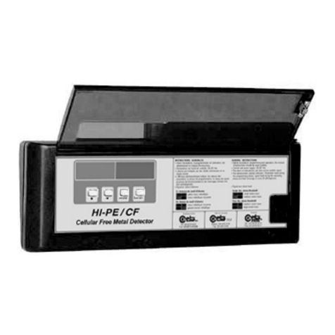
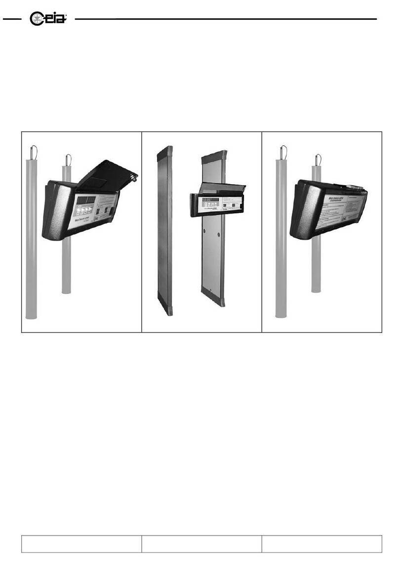
Ceia HI-PE multi-zone Series Quick start guide

HI-PE multi-zone --- Rev. FI 050 GB 60K10 v2_1
1
ATTENTION!
This manual contains the necessary instructions for the CEIA equipment described in the test report attached to the end of the
manual itself (Factory Acceptance Test Report). These instructions are not, generally, applicable to equipment different from
that described in the test report.
Rev.:
FI 050 GB 60K10 v2_1 Program Version:
8.11 Date:
2005-04-18
METAL DETECTOR
HI-PE multi-zone
Installation Use and Maintenance

HI-PE multi-zone --- Rev. FI 050 GB 60K10 v2_1
2
Installation, use and safety information
READ THESE INSTRUCTIONS BEFORE WORKING WITH THE DEVICE
CEIA can not be held responsible for direct and/or indirect damage to persons and/or property arising
from failure to observe these instructions.
•Read this manual carefully before installing, operating or
carrying out maintenance on the device. Keep this booklet in
a safe place for future reference.
•Follow the instructions contained in this manual for all
operations relating to installation, use and maintenance of the
device. CEIA cannot be held responsible for any damage
resulting from procedures which are not expressly indicated in
this manual.
•The final user is responsible for selecting the appropriate
security level/sensitivity for their application. After this
selection has been made, and programming has been
adjusted accordingly, it is also the final user's
responsibility to verify calibration using the test object(s)
appropriate to the level of security selected. Additionally,
this test should be carried out periodically to insure no
changes have occurred in the equipment.
•Whenever there is any suggestion that the level of protection
has been reduced, the device should be taken out of service
and secured against any possibility of unintentional use, and
authorised service technicians should be called.
The level of protection is considered to have been reduced
when:
- the device shows visible signs of deterioration;
- the device does not operate correctly;
- the device has been stored for a long period in sub-optimal
conditions;
- the device has suffered severe stress during transport;
- the inside of the device has come into contact with liquids.
•Choose the installation site carefully. Avoid placing the device
in locations where it may be directly exposed to sunlight, in
unventilated areas or in places that are close to sources of
heat. In addition, avoid places that are subject to vibrations,
dust, humidity, rain and excessively high or low
temperatures.
•Installation must be carried out by qualified personnel. Given
the dimensions of the device, it is requested that the
installation site be kept clear while work is carried out to
facilitate setting it up and to avoid any harm to third parties.
•Position the device as far away as possible from sources of
electromagnetic interference such as transformers or motors.
•When installation is completed, the detector must be
anchored to the ground in a stable manner and not subject to
vibrations (use expansion screws inserted through the
anchoring holes in the base of the panels). All connecting
cables between the gateway and the power supply or other
external devices must be properly fixed and protected so as to
achieve the best performance from the detector and avoid
accidental injury to people who might trip over them.
•Handle the device with care and without excessive force
during installation, use and maintenance
•Before powering up the device, check that the mains power
supply voltage corresponds to the voltage shown on the
device's electrical specifications plaque. The use of a
different mains voltage may damage the equipment!
The device should be connected to the mains voltage only
after all the connections required for full installation have been
carried out.
•The device must be connected to a power supply circuit fitted
with a switch or other device which allows the power to be cut
off.
•If the device is to be powered via an external autotransformer
to regulate the voltage, ensure that the common terminal of
the autotransformer is connected to the neutral of the power-
supply circuit.
•The power-supply plug must only be inserted into a socket
fitted with an earth/ground connection.
Any break in the safety conductor, either inside or outside the
device, or disconnection of the earth/ground safety terminal,
will render the device dangerous. Intentional cutting or
disconnection is strictly forbidden.
•Always remove the plug by hand when disconnecting the
power supply cable, never by pulling on the cable.
•The standard power-supply adapter is not waterproof: place it
in a ventilated position where it is protected from water (rain,
condensation, liquid detergents)! There is a risk of electric
shocks for people and damage to the equipment!
•This device contains electrical and electronic components,
and may therefore be susceptible to fire. Do not install in
explosive atmosphere or in contact with inflammable material.
Do not use water or foam in the case of fire when the device
is powered up.
•To prevent damage by lightning, disconnect the power supply
cable during thunderstorms.
•Do not use in an explosive atmosphere. Avoid contact with
inflammable or explosive material.
•Carry out the periodic maintenance regularly (see section on
Maintenance). Do not wash the device with water, liquid
detergents or chemical substances. Use a slightly moist, non-
abrasive cloth for cleaning.
•The device must be disconnected from all power sources
before undergoing any maintenance or cleaning, and before
being moved.
•Read the chapter on “Maintenance” carefully before calling
the service centre.
Whatever the problem, only specialised service personnel
authorised to work with CEIA equipment should be called.
•Any damaged parts of the device should be replaced by
original components only.
•Any maintenance or repair involving the device being opened
while powered should be avoided as far as possible: if this
becomes inevitable, the operation must be carried out only by
qualified personnel who are fully aware of the risks involved.
•Important advice regarding any batteries incorporated in
the device. When replacing: use CEIA spare parts or
batteries with equivalent electrical/mechanical characteristics.
Do not dispose of used batteries in general rubbish bins; use
public battery collection facilities as per local regulations, or
return them to a CEIA office. If the equipment is to be
disposed of, remove the batteries and dispose of them
separately. CEIA will not hold itself responsible for the
improper use of the batteries incorporated into its equipment:
consult the battery manufacturer for more detailed
information.
•Human exposure to electromagnetic fields. The equipment is
pre-set in the factory according to the regulations applicable
in the destination country. Any modification to this pre-setting
is the responsibility of the installer. For further information
contact the competent bodies. CEIA’s technical/sales
department can provide further clarification.

HI-PE multi-zone --- Rev. FI 050 GB 60K10 v2_1
3
Symbols
The device is marked with this symbol whenever the operator or the maintenance personnel,
in order to avoid possible damage, have to refer to the present manual. The same symbol
appears in the booklet at points where warnings or particularly important instructions are given -
instructions that are vital to a safe and correct use of the device.
The device is marked with this symbol in those areas where a dangerous amount of voltage is
present.
Only specialised maintenance personnel should make adjustments in these areas.
This sign in the manual indicates tips for optimising the device’s performance.
Warranty conditions
The warranty on all CEIA products, extended to the period agreed with the Sales Department, is applicable to goods
supplied from our factory, and for every constituent part thereof, with the exception of the batteries and the card reader.
Any form of tampering with the device, and in particular opening its container, is strictly forbidden and will invalidate the
warranty.
Customer Satisfaction Report
Your suggestions and comments on the products and services offered by CEIA and its distribution network
are extremely important for improving our procedures. We would ask you to send them to us by compiling and
returning the form available:
http://www.ceia.net/security/satisfaction.asp.
Thank you for your kind interest and co-operation.
CEIA reserves the right to make changes, at any moment and without notice, to the models (including programming), their
accessories and optionals, to the prices and conditions of sale.

HI-PE multi-zone --- Rev. FI 050 GB 60K10 v2_1
4
CONTENTS
INSTALLATION, USE AND SAFETY INFORMATION 2
SYMBOLS 3
WARRANTY CONDITIONS 3
CONTENTS 4
I - DESCRIPTION 5
OPERATING PRINCIPLE 5
Models 6
CONSTRUCTION OF THE METAL DETECTOR 6
Electronics Unit 6
Archway 7
Standard Model 7
Mains adapter 7
OPTIONS 8
Transit counter 8
Emergency batteries 8
II - INSTALLATION 9
ASSEMBLY 9
Unpacking the Metal Detector 9
Mechanical assembly 9
Assembly of the probe 9
Fixing the electronics unit 10
Positioning 11
Fixing the antenna to the ground 11
Electrical assembly 12
Connecting the electronics unit to the archway
(antenna). 12
Power supply connection 12
Outdoor model for outdoor applications:
assembly 13
Examples of Installations 14
Application in an airport environment 14
Transit flow-rate and secondary metal
detector for inspection in case of alarm 16
Installation of coupled metal detectors -
synchronisation 17
III - SWITCHING ON AND DISPLAY MESSAGES 18
SWITCHING ON THE METAL DETECTOR 18
DISPLAY MESSAGES 18
Alarm indications 18
Other messages 19
Messages activated via the keypad 19
VISUAL ALARM ZONE INDICATION 20
STAND-BY 21
IV - PROGRAMMING 22
LOCAL PROGRAMMING 22
COMMAND EXECUTION -LOCAL PROGRAMMING 22
Time out 23
DESCRIPTION OF THE COMMANDS 23
Reception Parameters 23
Transmission parameters 24
Alarm signal parameters 24
Management of the Metal Detector 24
ANALYSIS PROGRAMS AVAILABLE WITH
THE COMMAND "IS" 27
INSTALLATION CHECKS 28
ADVANCED PROGRAMMING -REMOTE PROGRAMMING 30
Serial communication 30
Communication system configuration 31
Free access to programming phase (without
password) 31
Execution of commands in remote programming 31
SIMULTANEOUS ACCESS REQUEST BY REMOTE AND
LOCAL PROGRAMMING 31
ADVANCED PROGRAMMING: USE OF THE
PASSWORD 32
Programming levels 32
Password definition 32
Access to the programming phase using the
password 33
Programming without password 33
Parameters accessible from remote
programming only 34
V - TECHNICAL CHARACTERISTICS 35
VI - MAINTENANCE 36
SUGGESTED MAINTENANCE SCHEDULE 36
DIAGNOSIS 37
TROUBLESHOOTING 38
COMPATIBILITY ASPECTS 39
PROCEDURES 40
Autotest program 40
ALP card: trouble-shooting diagram 40
Battery replacement procedure 41
VII - APPENDICES 42
DECLARATION OF CE CONFORMITY 42
ELECTRICAL CONNECTIONS 43
ACCESSORIES 44
MAIN & BATTERY SUPPLY UNIT 44
Personal Effects Depository 44
SPARE PARTS 45

HI-PE multi-zone --- Rev. FI 050 GB 60K10 v2_1
5
I - DESCRIPTION
Operating Principle
In general, a modern Metal Detector for checking people in transit comprises:
• An electronics unit, made up of:
• a variable magnetic field
generator
• a receiver
• a processing and control unit,
which determines if the variation
of the received signal is due to
metal masses in transit of a
certain shape, volume or
composition
• a transceiver antenna in the
form of an archway
Field
Generator Receiver
Processing and Control Unit
Transmitter
Antenna Receiver
Antenna
Antenna
Electronics unit
Fig. I-1: general block diagram of a metal detector
SOME HELPFUL GUIDELINES FOR METAL DETECTORS
The parameters which best characterise a Metal Detector are as
follows
• Discrimination:This parameter reflects the variation in
sensitivity between potentially dangerous metal objects (due to
their particular shape compared with their volume) and personal
effects (such as coins, keys, watches, buckles, etc...). When a
detector with low discrimination is used, personal effects can
cause a large number of false alarms, rendering the system
ineffective in practical terms.
• Uniformity in detection efficiency: This parameter is closely
connected with the linearity of the magnetic field generated
inside the Metal Detector. Generally speaking, the greater the
uniformity, the better the discrimination.
• Sensitivity: alarm activation threshold: the greater the
sensitivity, the smaller the metal mass which will cause an
alarm.
• Interception speed: the transit speed of a person through the
metal detector archway usually depends on situational factors,
and can vary considerably. The sensitivity of a good Metal
Detector should be independent of the speed of transit.
• Programming: C.E.I.A. have designed their Metal Detectors to
include the possibility of selecting the settings of the operational
parameters: this predisposition facilitates both the installation of
the device (rejection of external sources of interference) and
adaptation to the user’s requirements (orientation towards
ferromagnetic and/or non-magnetic metals). This feature is
particularly important in the detection of weapons made of light
metal.
• Immunity to interference: environmental electromagnetic
interference of mechanical or electrical origin is the principal
cause of false alarms, because it augments the effective signal
of the mass to be detected. Particular attention must therefore
be paid to the Metal Detector’s immunity to this type of
interference.
• Harmlessness to life support systems and storage media: the
field emitted by the Metal Detector should be below the values
set by international standards which guarantee harmlessness
to life support systems such as pace-makers, adrenaline
pumps etc. Observance of these limits also means that there
is no effect whatsoever on computer-type storage media.
• Synchronisation: multiple installations of Metal Detectors are
very common (just think of an airport departure terminal). To
allow several Metal Detectors to operate in a restricted area
without influencing each other, it must be possible to
synchronise them without the help of cable connections.
• Power supply flexibility: wide tolerance range for the input
voltage and emergency batteries which cut in automatically
ensure that the Metal Detector continues operating in the case
of variations or cuts in the mains supply.
• Set-up and calibration with respect to the reference sample: a
modern Metal Detector must allow its installation in whatever
environment, without any interference caused by other
external devices. The security level may usually be adjusted
acting on sensitivity: CEIA’s Metal Detectors are also provided
with a special command (IS) allowing the direct selection of
the functioning parameters which determine a security level
conforming to the International Standards.
• Maintenance: a modern Metal Detector generally incorporates
a self-diagnosis system which identifies any sabotage and
which also signals accidental faults. Modular construction
furthermore allows the faulty parts to be replaced quickly and
easily, thereby minimising the time the device is out of
operation.

HI-PE multi-zone --- Rev. FI 050 GB 60K10 v2_1
6
Models
Series Model Description Standard configuration/Options
HIPE/PTZ
Standard panel model
Intended use:
indoor applications
(IP20)
Standard configuration
•Electronics unit in IP20 plastic casing
•IP20 archway with 720mm useful width, equipped
with connection module without emergency
battery
Options
•IP20 archway with 760mm useful width
•IP20 archway with 820mm useful width
•Connection module with emergency battery (30’).
•Photocells for transit counting
HI-PE multi zone
HIPE /PTZ-WP
Outdoor panel model
Intended use:
indoor/outdoor
applications
(IP65)
Standard configuration (full options)
•Electronics unit in IP65 metal casing
•IP65 archway with 760mm useful width, equipped
with:
•Connection module with emergency battery
(30’)
•Photocells for transit counter
Construction of the Metal Detector
CEIA Metal Detectors are made up of an electronics unit and an archway antenna; the connection between
the two is via two cables (one for the transmitter and one for the receiver ).
Electronics Unit
The electronics unit, which is extremely compact, is available in an shock-resistant plastic casing, with
protection grade IP20, or in a tight metal container, with protection grade P55 (for the outdoor model).
Both casings are designed to be attached directly to the crossbar of the archway.
Fig. I-2a: electronics unit in IP 20 casing Fig. I-2b: electronics unit in IP65 casing
The alphanumeric display (3) and the programming keypad (4) are situated at the front, protected by a
transparent panel (1) fitted with a security lock (2). A cover (5) on the top of the unit protects the terminal
board and connectors to which the antenna, power supply, serial and slave connections are made.
1
4
2
3 1
4
5
2
3

HI-PE multi-zone --- Rev. FI 050 GB 60K10 v2_1
7
Archway
This model is for the most part employed airports, ports, embassies, military installations, manufacturing
premises and stadiums. The panels are manufactured in exceptionally robust synthetic material.
The archway incorporates two bars which light up in the case of an alarm to show the height at which the
metal mass has been detected.
+ 115 (4" 1/2)
2050 (80" 3/4)
660 (26")
2255 (88" 3/4)
+ 50 (2")
630 (24" 3/4)
ø 6.5 (ø 1/4")
t
EU
RX TX
Standard Model
EU electronics unit
RX receiver panel
tcross-bar
TX transmitter panel
UW = 720mm (760mm or
820mm optional)
Fig. I-3a Dimensions
t
EU
TX RX
UP
LP
Outdoor Model
(for outdoor
applications)
EU electronics unit
LP protection of the
lower connection
module
RX receiver panel
tcross-bar
TX transmitter panel
UP upper protection
UW =760mm
Fig. I-3b Dimensions
Mains adapter
Input voltage: 230Vac (CEE plug) or 115Vac /100Vac (UL plug)
Dimensions: 121 x 80 x 71 (LxWxH)
Cable length - plug side: 2m
Cable length - electronics unit side: 2m
Weight: 1,5 kg.
Protection degree: IP30
Fig. I-4

HI-PE multi-zone --- Rev. FI 050 GB 60K10 v2_1
8
OPTIONS
Transit counter
Two photocells fitted into the antennae allow counting of transits, alarms and percentage of alarms.
TX
Fig. I-5a Photocells
RX
Fig. I-5b Reflectors
RXTX
Emergency batteries
Two 12V-0,8Ah batteries built into the antenna switch in automatically and allow about 30 minutes of
independent operation in the event of a mains failure. The batteries recharge automatically when the metal
detector is connected to the AC power supply and switched on.
Use of the emergency batteries is signalled by a flashing letter "B" on the electronics unit display. Recharge
time is about 8 hours.
The batteries (2) are housed in a compartment located in the upper part of the TX panel and are connected
to the recharging card AB via the connectors (4).
1 cover
2 batteries (model NP
0.8-12 Yuasa)
3 card ALP (battery
charger)
4 battery connectors
5 connector for internal
connections
Fig. I-6
4
4
5
1
2
3
2

HI-PE multi-zone --- Rev. FI 050 GB 60K10 v2_1
9
II - INSTALLATION
Before proceeding to install the device read the warnings and instructions in this section and in the
paragraph “Installation, use and safety information” carefully. Please note that CEIA is not responsible for
any damage that may result from installations that do not follow these guidelines.
Assembly
Unpacking the Metal Detector
Opening the packaging.
Cut the bands with scissors and
open the top side of the box.
Before taking out the components,
remove the staples that join the
strips of cardboard with pincers to
avoid injury or damage to the
e
q
ui
p
ment.
Handle the material with care during
unpacking operations, to avoid injury to
people or damage to the equipment.
All accessories needed for assembly of
the Metal Detector are supplied with the
device
EU
CH
tr1 M
RX
TX
tr2
IK
PL
CA
PL
CA customer address
EU electronics unit
IK installation kit
M manual
PL list of materials
RX receiver panel
tr1 cross-bar
designed for
fixing the
electronics unit
tr2 second cross-bar
TX transmitter panel
Mechanical assembly
Assembly of the probe
Refer to figures II-1a and II-1b. Connect the panels to the cross-bars tr, using the wrench provided to tighten
the screws vt fully (about 15 Nm). The transmitter panel (TX) can be recognised by the connector at the
bottom..
The probe can be assembles in two different configurations, both
having the same level of performance:
•configuration A (with TX panel on the left when facing the
exit side)
•configuration B (With TX panel on the right when facing
the exit side)
The choice between the two configurations should be made based
on installation requirements: see notes on the following pages (in
particular, the paragraphs “Application in an airport environment”
and “Installation of coupled metal detectors - synchronisation”).
RX
TX
PSA
Configuration A
TX on left
RX
TX
PS
A
Configuration B
TX on right

HI-PE multi-zone --- Rev. FI 050 GB 60K10 v2_1
10
Fixing the electronics unit
Refer to figures II-1a and II-1b. Fix the electronics unit EU to the cross-bar tr1 using the wrench provided to
tighten the screws vc fully (about 1.2 Nm).
vt
TX
ca
vc
Ctx
RX
Crx
tr1
cc
tr2
cp1
BD1
BD2
vc
vt
vt
vt
PSA
cc cc
cp2
EU
RX
TX
PSA
Configuration A: TX on left
Fig. II-1a
vt
RX
vc
Crx
TX
Ctx
tr1
cc
tr2
BD2
vc
vt
vt
vt
ca PSA
cc cc
EU
BD1
cp1
cp2
RX
TX
PS
A
Configuration B: TX on right
Fig. II-1b
BD1, 2 LED bar
ca power-supply cable
cc central cable fixing
groove
CH chip card
cp1 lower connection module
cp2 upper connection module
Crx RX panel – electronics
unit cable
Ctx TX panel – electronics
unit cable
EU electronics unit
PSA power supply adapter
RX receiver panel
tr1 cross-bar designed for fixing
the electronics unit
tr2 second cross-bar
TX transmitter panel
vc electronics unit fixing screws
vt cross-bar fixing screws
Allen wrench for
crossbar
Allen wrench for control
unit
Control unit
keys
Screws for
the control
unit
RS232 connector
covers
Cross-bar fixing screws
Installation kit

HI-PE multi-zone --- Rev. FI 050 GB 60K10 v2_1
11
Positioning
Transit requirements
The Metal Detector will be positioned, according to the requirements dictated by the transit, in such a way as
to allow the maximum flow of people and observance of the rules for installation.
See notes on the following pages for correct positioning.
Minimum distances - Electrical and mechanical compatibility
General Rules:
- avoid movement of significant metal masses less than 70 cm from the Metal Detector antenna;
- avoid the presence of electric lines and electrical devices less than 30 cm from the metal detector probe,
especially the receiver section (RX).
- move electrical/electronic devices (e.g. motors or switching power supplies) in general away from the
metal detector probe, especially the receiver section (RX): the distance depends on the type and power
of the device.
IMPORTANT!
The distances mentioned are indicative only:
The amount of interference should be assessed at the time of installation (see paragraph “Installation
Check”).
---- …*no signal or one green asterisk: interference acceptable!
Fixing the antenna to the ground
To fix the antenna to the ground
screw the expansion screws (vf)
into the floor through the holes
provided in the base flanges.
Carefully check the
perpendicularity and alignment of
the transmitter and receiver
sections, ensuring that they are
anchored at the right distance
vf
Fig. II-2a
+ 50 (2")
630 (24" 3/4)
ø 6.5 (ø1/4")
UW= 720/760/820mm
Fig. II-2b - Diagram of holes for
fixing to ground
Stability
To operate properly the antenna should not be subject to shocks or movements. Follow the installation
instructions and ensure that the Metal Detector probe is stable and anchored firmly to the ground using screws
or silicone. Check the rigidity of the floor; in particular, avoid installation on:
•
Wood floors
•
"technical"-type floors, as these generally do not rest on surfaces which guarantee stability over their whole
area.
Holes
It is strictly forbidden to make holes in the Metal Detector antenna or to insert screws in positions, or of lengths,
not expressly indicated by CEIA. Damage due to such actions is not covered by the product warranty.

HI-PE multi-zone --- Rev. FI 050 GB 60K10 v2_1
12
Electrical assembly
All connecting cables between the gateway and the power supply or other external devices must be properly
fixed and protected so as to achieve the best performance from the detector and avoid accidental injury to
people who might trip over them.
Connecting the electronics unit to the archway (antenna).
TX ANTENNA
60xxx t
Ctx
RX ANTENNA
60xxx r
Crx
•Refer to figures II-1a
and II-1b.
The electronics unit is
fitted with two cables for
connection to the
antennae (Crx for the
receiver panel, Ctx for
the transmitter panel).
The connectors of the
receiver and transmitter
panels are located on
the top of the units.
•Attach the cables to the
cross-bar using the
grooves (cc) provided.
cc
Fig. II-2c
Power supply connection
Refer to figures II-5a e II-5b.
The TX panel incorporates a low-voltage power-
supply section: the connection panel (cp1) is located
low down, and, in addition to the power-supply
connection socket DC, includes the connector for
serial communication (B PORT). The mains power
adapter PSA should be connected to connector DC.
ca cp1
PSA
The connections panel is also designed for the
insertion of two emergency batteries (see Options
section).
The panel Metal Detector is provided with an
additional connection module located in the upper
part of the TX panel (cp2): this allows the
connections to be made via cables coming down
from the ceiling.
B-PORT
L1
S1
DC
c
p
1
B-PORT serial communication
port
cp1 lower connection
module
DC power-supply cable
connector
L1 power indicator
S1 On/Off switch
Fig. II-2d
T-PORT
TXc
DC
c
p
2
PSA
ca
ca power supply cable
cp2 upper connection
module
DC power-supply cable
connector
PSA power supply adapter
T- PORT serial communication
port
TXc TX panel connector
for cable connecting
the control unit to the
TX panel
Check that the voltage supplied by the mains corresponds to the detector’s supply voltage: this latter is
indicated on the device’s power supply adapter and on the test report at the end of this booklet.
The use of a different mains voltage may damage the equipment!
The standard power-supply adapter is not waterproof: place it in a well-ventilated position where it is protected
from water (rain, condensation, liquid detergents).
A protection switch should be connected up between the mains supply and the detector. The external
grounding line should conform to standards and should not in any case have a resistance greater than 3
Ohm.
Auxiliary connections: see appendix.

HI-PE multi-zone --- Rev. FI 050 GB 60K10 v2_1
13
Outdoor model for outdoor applications: assembly
A B
C
A: upper protection
B: lower connection module protection
C: threaded knobs
Kit composition
B
1 2
3
A
4
A
C 5

HI-PE multi-zone --- Rev. FI 050 GB 60K10 v2_1
14
Examples of Installations
Application in an airport environment
TP
MO
MD
RP
XR
40cm!
RX
TX
40cm!
100cm!
The following notes refer to an airport departure
terminal equipped with an X-ray unit for
personal effects and a metal detector to
intercept any weapons carried by passengers.
Siting of the devices
Care must be taken in the siting of the
devices to avoid electromagnetic interference.
The RX antenna of the MD metal detector
should ideally be located as far as possible from
the monitor (MO) and conveyor belt of the X-ray
inspection device (XR).
Site the transmitter antenna (TX), recognisable
by its power-supply connector, next to this
device.
AP
Auxiliary passage
Wherever possible provide a passage dedicated
to service personnel transit (AP), which will
allow the passage of material and equipment for
the cleaning and maintenance of the area.
It will not therefore be necessary for the staff to
pass through the Metal Detector, and the
possibility of accidental blows and damage to
the detector will be avoided
MD1
XR
WL !
!
Fig. II-3
Movement of luggage
In order to avoid false alarms from the metal
detector due to movement of luggage near the
archway, it is advisable to locate it at equal
distance from the beginning and end of the
conveyor belt, where the luggage is taken back
by passengers. It is also advisable to stop
passengers crowding into the entrance by
placing channelling barriers near the access
control system (WL: waiting line).

HI-PE multi-zone --- Rev. FI 050 GB 60K10 v2_1
15
MD1
XR
METAL
Barriers
It is recommended that the barriers be made of
insulating material (wood, glass, lexan, plastic
panelling, cordons, architectural embellishments
in insulating materials), so that any movement
due to knocks do not affect the antenna of the
metal detector.
For the same reason, avoid direct contact
between the barriers and the probe of the metal
detector.
MD1
XR
OHT
~2cm
CEIA Personal Effects Depository
We recommend placing a CEIA Personal
Effects Depository (OHT) between the metal
detector probe and the X-ray unit
This article acts both as a spacer between the
X-ray unit and the metal detector and as a
temporary depository for metal personal effects
which are not of dubious nature and therefore
not required to undergo X-ray analysis (coins,
keys and so on).
In this case, again, avoid direct contact between
the depository and the metal detector probe.
Fig. II-3b

HI-PE multi-zone --- Rev. FI 050 GB 60K10 v2_1
16
Transit flow-rate and secondary metal detector for inspection in case of alarm
Medium-low flow-rate application: manual secondary metal detector Should the alarm sound, locate
and identify the metal objects
being carried by making the
person pass through the gate
several times or, if necessary,
by using the hand-held metal
detector.
TX
TX
HHMD
HHMD
OHT
OHT
MO
MO
AP
PrMD
PrMD
>100
XR
XR
Fig. II-4a
AP
HHMD
MO
OHT
PrMD
RX
TX
XR
Possible transit for
service personnel
Hand-held metal
detector CEIA PD140
Monitor of the X-ray
unit
CEIA Personal Effects
Depository
Primary metal
detector HI-PE or
02PN10
Receiver antenna
Transmitter antenna
X-ray unit
High flow-rate application: secondary metal detector with zonal detection Should the alarm of the primary
metal detector sound, locate
the metal objects being carried
using the secondary metal
detector.
TX
TX
SeMD
OHT
OHT
MO
MO
AP
PrMD
PrMD
>100
XR
XR
Fig. II-4b
AP
MO
OHT
PrMD
RX
SeMD
TX
XR
Possible transit for
service personnel
Monitor of the X-ray
unit
CEIA Personal Effects
Depository
Primary metal
detector HI-PE or
02PN20
Receiver antenna
Secondary metal
detector PMD2 with
interception zone
Transmitter antenna
X-ray unit

HI-PE multi-zone --- Rev. FI 050 GB 60K10 v2_1
17
Installation of coupled metal detectors - synchronisation
When two or more Metal Detectors are to operate near each other (generally within 10 meters), they must be
synchronised by choosing an appropriate transmission channel for each one (CH function).
1. Follow precisely the arrangement of the TX and RX antennas and the minimum distances indicated. The
TX antenna can be recognised by the power supply connector.
2. Select the 0 setting for the NL function.
TX
RX
MD1
RX
TX
MD2
d
NL = 0 !
d ≥5cm
50Hz power supply 60Hz power supply
MD1 MD2 MD1 MD2
CH=1 CH=2
CH=51 CH=52
Fig. II-5a Installation of 2 Metal Detectors
TX
RX
MD1
RX
TX
MD2
TX
RX
MD3
RX
TX
MD4
ddd
NL = 0 !
d ≥15cm
50Hz power supply 60Hz power supply
MD1 MD2 MD3 MD4 MD1 MD2 MD3 MD4
CH=1 CH=2 CH=3 CH=4
CH=51 CH=52 CH=53 CH=54
Fig. II-5b Installation of three or four Metal Detectors

HI-PE multi-zone --- Rev. FI 050 GB 60K10 v2_1
18
III - SWITCHING ON AND DISPLAY MESSAGES
Before working with the device read the warnings and instructions in this section and in the paragraph
“Installation, use and safety information” carefully. Please note that CEIA is not responsible for any
damage that may result from installations that do not follow these guidelines.
Switching on the Metal Detector
After turning ON the equipment, an audible signal will sound and the display of the electronics unit will show
the following information:
CEIA
HIPE-PTZ
****
- - - -
Fig. III-1a
Manufacturer
Model
Alarm indication test
Normal operating
L1 power supply LED indicator
S1 On/Off switch
Fig. III-1b Detail of the lower
connection module
Display messages
During operation the following messages may appear on the display (see also AD command, Programming
section).
Alarm indications
Messages with AD =0P-5P (see Programming section).
Display Buzzer Meaning
- - - -
NORMAL FUNCTIONING
without metal masses in transit
*
**
***
****
small metal mass O
O
O
medium metal mass O
metal mass under the alarm threshold
*
**
***
****
Fig. III-2
AD
medium metal mass O
O
O
large metal mass O
metal mass over the alarm threshold:
duration of alarm indication determined
by the value of AD.
Messages with AD =0C-5C (see Programming section).
Display Buzzer Meaning
SE31 Normal operation or metal mass under the alarm threshold (sensitivity indication)
****
Fig. III-3 AD
Metal mass over the alarm threshold: duration of alarm indication determined by
the value of AD.
L1
S1

HI-PE multi-zone --- Rev. FI 050 GB 60K10 v2_1
19
Other messages
Emergency battery power – mains voltage absent
Display Buzzer Meaning
- - - - B
Fig. III-4a
- Emergency battery power supply is only indicated by a flashing letter “B” on the right of
the display.
Warnings
Display Buzzer Meaning
GATE EV
Self-diagnosis (example shows message indicating antenna damaged or disconnected
from the electronics unit)
WAIT
Fig. III-4b
Implementation phase of operating parameter modification. Metal Detector not
operational (alarm relay activated).
Messages activated via the keypad
When keys or are pressed, the display shows, in sequence, the values of some operating
parameters without having to enter programming mode (see also Programming section).
Normal
operation
indicator
Security level Number of
inward transits Number of
outward
transits
Normal
operation
indicator
Action Parameter Possible messages
AU
(Autoset)
AUTOSET Standard operation obtained via the AU (Autoset) function.
N.B.: the AUTOSET function is pre-set in the factory for all detectors.
IS
NILECJ 1 Operation in line with standard NILECJ 0601.00, level 1, obtained via the
IS (International Security Standards) function.
For the other possible settings, see Programming section.
(International
security
standards)
NILECJ 1
MODIFIED
NILECJ 1
:
Operation in line with standard NILECJ 0601.00, level 1, obtained via the
IS (International Security Standards) function, but with sensitivity setting
modified (parameter SE).
The two messages alternate on the display.
NO SET Operation differs from the standards selectable using the AU and IS
functions. In addition to the sensitivity, it is possible to adjust another
parameter which influences the response of the detector to metals (see
sub-section “Received signal parameters” in the Programming section).
CI
(Count in)
C I 102 Number of transits through the gate in the direction defined by parameter
GD (gate direction).
The read-out is updated in real time.
Fig. III-5 CO
(Count out)
CO 15 Number of transits through the gate in the opposite direction to that defined
by parameter GD (gate direction).
The read-out is updated in real time.
N.B.: the messages described above remain activated until the or key is pressed: this allows the operator to
check, for example, the number of inward transits over the whole shift.

HI-PE multi-zone --- Rev. FI 050 GB 60K10 v2_1
20
Visual alarm zone indication
The special feature of this model is that it indicates the height of the metal mass intercepted inside the
archway by means of the LED bar located on the transmitter antenna. In the case of an alarm, one or more
groups of the lights that make up the bar will come on to indicate the zones in which the metal masses have
been detected.
Under non-alarm conditions, a power-indicator light (continuous or blinking depending on the value of
parameter BM; see Programming section) can be seen at the top of the bar display.
The panel model has two light bars, the function of which is set by the GD parameter.
Fig. III-6a - alarm indication for a single
metal mass Fig. III-6b - alarm indication for two
metal masses Fig. III-6c -power indicator
Three choices of operating mode, floating (standard), 4 fixed zones and 8 fixed zones can also be chosen
using the ZN function (see Programming section).
Fig. III-6d - 4-zone operation
(ZN=4): when a metal mass is
detected, one of 4 distinct
zones, each of fixed height and
position, lights up.
Fig. III-6e - 8-zone operation
(ZN=8): when a metal mass is
detected, one of 8 distinct
zones, each of fixed height and
position, lights up.
In fixed-height zone operation, the alarm threshold can
be adjusted individually for each zone using the
settings Z1...Z4 or Z1...Z8 (see Programming section).
Fig. III-6f - Floating-zone operation (ZN=FLOA):. a group of
LEDs lights up at the height of transit of the metal mass (20
different zones of variable height and position).
This manual suits for next models
2
Table of contents
Other Ceia Metal Detector manuals