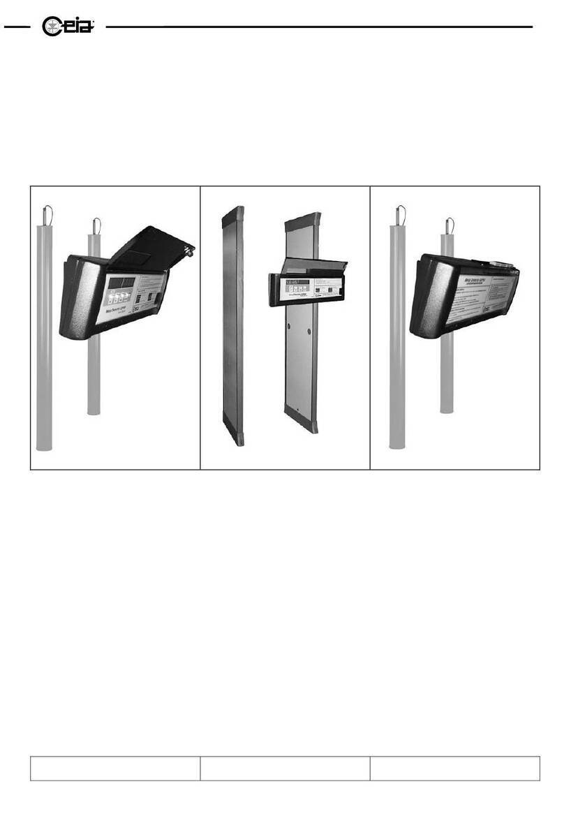
Ceia THS/21E Reference manual

FI002K0018v1100UK – THS/21 Instruction manual for installation, use and maintenance
ORIGINAL INSTRUCTIONS 1
Industrial Metal Detectors
and Integrated Systems with Conveyor Belt
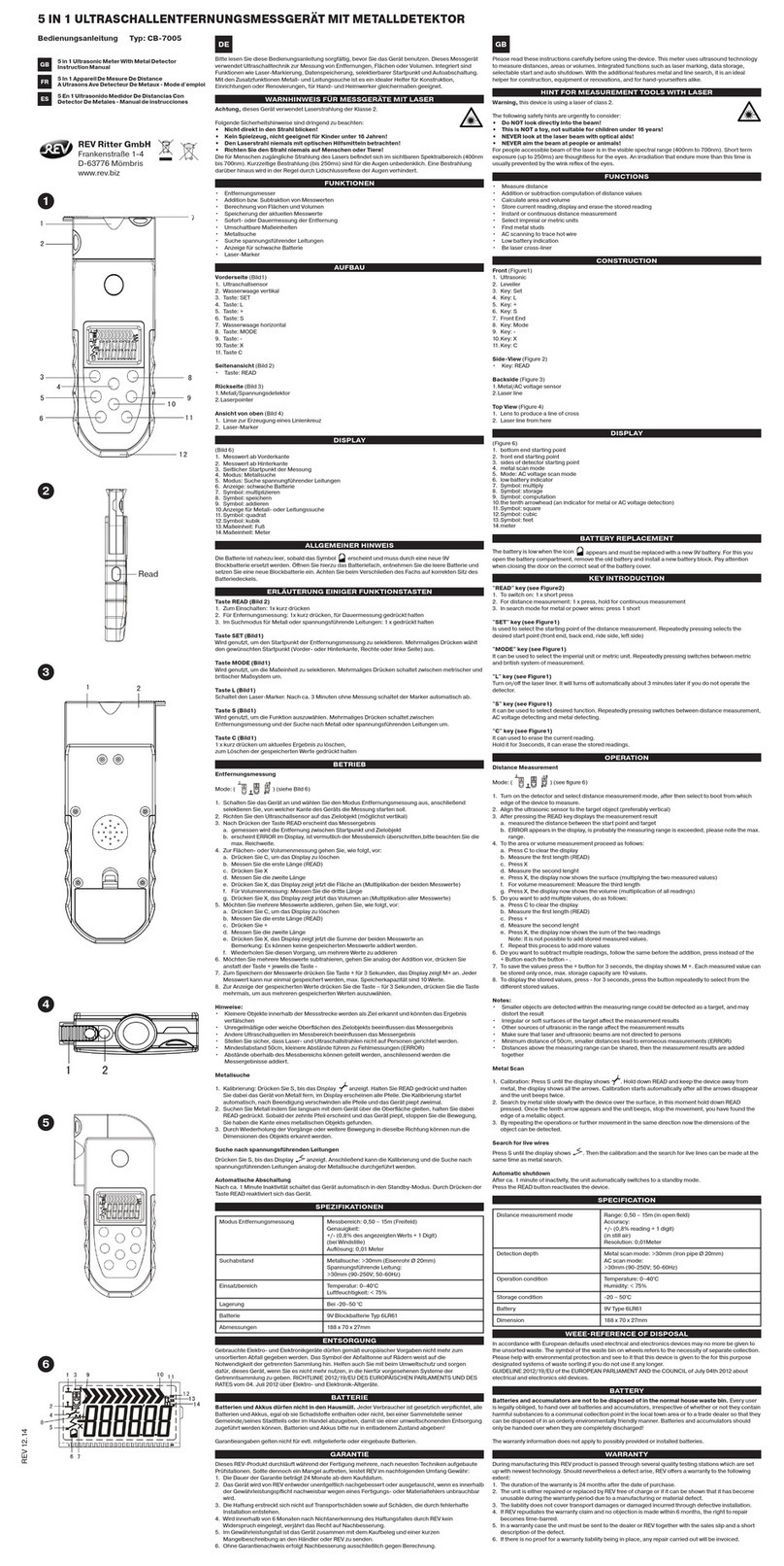
THS/21E - THS/21
Instruction manual
for installation, use
and maintenance
Document Date Hardware Software
FI002K0018v1100UK 2012-03-29 HV5.xx THSV5401 – ALMV5400
Read this manual carefully before installing, operating or carrying out maintenance on the device. Keep the manual in a
safe place for future reference and in perfect condition. This manual must accompany the device described herein in the
case of change of ownership and until the device is decommissioned.

FI002K0018v1100UK – THS/21 Instruction manual for installation, use and maintenance
2 ORIGINAL INSTRUCTIONS
SYMBOLS
The equipment is marked with this symbol wherever the user should refer to this manual in order to avoid possible
damage. The same symbol appears in the manual at points where warnings or particularly important instructions,
essential for safe, correct operation of the device, are given.
The equipment is marked with this symbol in the areas where there is dangerous voltage. Only trained maintenance
personnel should carry out work in these areas. The same symbol appears in the manual at points where essential safety
warnings are given.
The equipment is marked with this symbol in the areas where the user must be careful to avoid crushing of hands. Only
trained maintenance personnel should carry out work in these areas. The same symbol appears in the manual at points
where essential safety warnings are given.
The equipment is marked with this symbol in the areas where the user must be careful to avoid coming into contact with
moving components. Only trained maintenance personnel should carry out work in these areas. The same symbol
appears in the manual at points where essential safety warnings are given.
The equipment is marked with this symbol in the areas where the user must be careful to avoid crushing of feet. Only
trained maintenance personnel should carry out work in these areas. The same symbol appears in the manual at points
where essential safety warnings are given.
The equipment is marked with this symbol in the areas where there is the danger of unexpected bursts of compressed air.
Only trained maintenance personnel should carry out work in these areas. The same symbol appears in the manual at
points where essential safety warnings are given.
LASER LIGHT: This symbol appears in this manual at those points where warnings or information relating to laser
pointing devices are given. Such devices may be dangerous. It is therefore essential that the guidelines in this
manual be followed.
The equipment is marked with this symbol wherever the user must not have access to potentially dangerous areas.
CEIA Metal Detectors employ low intensity electromagnetic fields in compliance with current legislation.
MAGNETIC FIELDS can affect pacemakers. Wearers of pacemakers, cardiac defibrillators and other life support devices
must not operate in proximity of the inductor or the heating inductors of this device.
Wearers of pacemakers must not use the Metal Detectors of the THS/MN21 series which use static electromagnetic
fields. Wearers should consult their doctor for advice on avoiding this hazard.
This symbol appears in the manual at points where suggestions, additional information or other relevant notes are given.
REVISION HISTORY
Rev.
Date
Author
Reference
Description
1000
2010-09-16
TP2 – SP
-
First issue for all THS/21E and THS/21 models
1100
2012-03-29
TP2 – SP
2.3.2, 2.8.2,
3.2.1, 3.2.3,
3.2.4, 3.3.3, 3.5.2.2, 4.5.6, 5,
5.6
Small corrections
1.2.2, 1.2.3, 1.2.4, 1.3.2,
1.4.2, 2.5.4, 2.9, 3.6.2.1,
3.6.7, 3.6.7.1, 3.6.8, 3.14,
4.4.1, 5.1
Management of external emergency buttons and
other protections
2.8.2, 3.1.3, 4.5.6, 5.1
A
dditional indications on bins and respect for the
environment

FI002K0018v1100UK – THS/21 Instruction manual for installation, use and maintenance
ORIGINAL INSTRUCTIONS 3
CONTENTS
1SAFETY INSTRUCTIONS – WARNINGS.......8
1.1Device users, required instruction level
and training...............................................8
1.2Warnings.................................................10
1.2.1General warnings .....................................10
1.2.2Installation warnings.................................10
1.2.3Use warnings............................................12
1.2.4Maintenance warnings..............................14
1.3Permitted uses. Improper uses...............15
1.3.1Permitted use ...........................................15
1.3.2Improper use ............................................15
1.4Residual risks..........................................16
1.4.1Installation................................................16
1.4.2Operating..................................................16
1.4.3Maintenance.............................................16
2DESCRIPTION............................................... 17
2.1General description.................................17
2.1.1Detection probe........................................17
2.1.2Integrated conveyor..................................18
2.1.3Products that can be inspected ................18
2.2Detection Probes .................................... 19
2.2.1THS/21E and THS/21E-3F.......................19
2.2.2THS/21 and THS/MS21............................19
2.2.3THS/MN21................................................20
2.2.4THS/G21E................................................21
2.2.5THS/G21 and THS/GMS21......................21
2.2.6Applicable power supply boxes ................22
2.2.6.1Control Power Box (CPB)...................22
2.2.6.2Remote Control Unit (RCU)................23
2.2.6.3Conveyor Control System (CCS)........23
2.2.6.4Field Generator...................................23
2.2.6.5Small Size Power Supply Unit
(00211AL_ card).................................23
2.3Integrated system with conveyor belt .....24
2.3.1Inverting component positions..................25
2.3.1.1Inverting the antenna/PSU unit
position ...............................................25
2.3.1.2Inverting the ejection system position.25
2.3.2Models......................................................26
2.3.2.1THS/FBB (flat belt)..............................26
2.3.2.2THS/FB (flat belt)................................27
2.3.2.3THS/MBB (modular belt).....................28
2.3.2.4THS/M65 and THS/M69K (modular
belt).....................................................29
2.3.2.5THS/MBR (modular belt).....................30
2.4Device identification................................ 31
2.4.1Probe........................................................31
2.4.2Control Power Box....................................31
2.4.3Conveyor Control System.........................31
2.4.4CEIA conveyor structure...........................32
2.5Functional diagrams............................... 33
2.5.1THS with Control Power Box.................... 33
2.5.2THS with Conveyor Control System......... 33
2.5.3Integrated systems................................... 34
2.6Dimensions............................................. 35
2.6.1Probes...................................................... 35
2.6.1.1THS/21, THS/MS21, THS/21E,
THS/21E-3F ....................................... 35
2.6.1.2THS/SL21, THSSL21E....................... 36
2.6.1.3THS/MN21.......................................... 36
2.6.1.4THS/G21, THS/GMS21, THS/G21E... 37
2.6.2Power supply units................................... 38
2.6.2.1Control Power Box (CPB) and Field
Generator (MAG)................................ 38
2.6.2.2Control Power Box with Remote
Control Unit (THS/21E)....................... 38
2.6.2.3Control Power Box with Remote
Control Unit (THS/21)......................... 39
2.6.2.4Conveyor Control System................... 39
2.6.2.5Small size power supply unit
(00211AL_ card)................................. 39
2.6.3Integrated systems................................... 40
2.6.3.1THS/FBB............................................ 40
2.6.3.2THS/FB............................................... 40
2.6.3.3THS/MBB ........................................... 41
2.6.3.4THS/M65 and THS/M69K................... 41
2.6.3.5THS/MBR........................................... 42
2.7Options and Accessories........................ 42
2.8Technical characteristics........................ 43
2.8.1Metal Detector.......................................... 43
2.8.2Integrated systems................................... 45
2.9Safety devices ........................................ 46
3INSTALLATION............................................. 47
3.1General requirements............................. 47
3.1.1Minimum clearances................................ 47
3.1.1.1Probes................................................ 47
3.1.1.2Integrated systems............................. 47
3.1.2General installation guidelines for non-
integrated models .................................... 48
3.1.2.1Controls and Power Supply box......... 48
3.1.2.2Metal structures in proximity to the
probe.................................................. 49
3.1.2.3Customer conveyor belt...................... 51
3.1.3Installation guidelines for correct
environmental compatibility of the Metal
Detector ................................................... 55
3.1.3.1Power supply and control cables of
other devices...................................... 55
3.1.3.2Pulsed-type sources........................... 55
3.1.3.3Ground loops...................................... 56
3.1.3.4Conveyor belt motors ......................... 56
3.1.3.5Selecting and installing connecting
cables................................................. 57
3.1.3.6Multiple Metal Detectors close
together.............................................. 57
3.2Unpacking............................................... 57

FI002K0018v1100UK – THS/21 Instruction manual for installation, use and maintenance
4 ORIGINAL INSTRUCTIONS
3.2.1Metal Detector.......................................... 57
3.2.1.1Handling and moving the packaged
device................................................. 57
3.2.1.2Unpacking procedure ......................... 58
3.2.1.3Packing list ......................................... 58
3.2.1.4Moving the Metal Detector.................. 59
3.2.2CEIA Integrated Systems......................... 59
3.2.2.1Handling and moving the package
device................................................. 59
3.2.2.2Unpacking procedure ......................... 60
3.2.2.3Packing list ......................................... 60
3.2.2.4Moving the Metal Detector.................. 60
3.3Mechanical installation............................61
3.3.1Probe ....................................................... 61
3.3.2Integrated systems................................... 62
3.3.3Assembly of components......................... 62
3.3.3.1Metal Detector.................................... 62
3.3.3.2Integrated systems............................. 62
3.4Pneumatic installation.............................63
3.4.1Minimum requirements............................. 63
3.4.2Pneumatic circuit diagrams...................... 63
3.4.2.1Ejector cylinder or retracting belt........ 63
3.4.2.2Air jet ejection system......................... 63
3.4.3Connecting up to the compressed air
supply....................................................... 64
3.4.3.1Ejector cylinder or retracting belt........ 64
3.4.3.2Air jet ejector ...................................... 64
3.4.4Adjustment............................................... 64
3.4.4.1Ejector cylinder or retracting belt........ 64
3.4.4.2Air jet ejector ...................................... 64
3.4.5Padlocking the compressed air................ 64
3.5Electrical Installation...............................64
3.5.1Installing connecting cables..................... 64
3.5.2Description of inputs................................. 65
3.5.3Description of outputs .............................. 66
3.5.4Description of I/O interfaces..................... 67
3.5.5Communication connections.................... 67
3.5.5.1RS232 serial port connections............ 67
3.5.5.2Bluetooth communication................... 67
3.5.5.3Ethernet / WiFi connections (on
request, with IXC card)....................... 67
3.5.6Connection to the Production Line
emergency circuit..................................... 68
3.5.7Connecting a motor (Conveyor Control
System only) ............................................ 69
3.5.8Connecting to the mains power supply .... 70
3.5.8.1Connection to earth............................ 70
3.5.8.2Power Switch...................................... 71
3.6Electrical diagrams..................................72
3.6.1Functional diagrams................................. 72
3.6.1.1Control Power Box.............................. 72
3.6.1.2Conveyor Control System................... 72
3.6.2Control Power Box................................... 73
3.6.2.1ALM card............................................ 73
3.6.2.2Small Size Power Supply – ALM
card .................................................... 75
3.6.2.3Field Generator (MAG) for
THS/MN21..........................................76
3.6.2.4Conveyor Control System – ALM
card.....................................................78
3.6.3SCD card..................................................82
3.6.3.1THS/xx21E..........................................82
3.6.3.2THS/xx21E-3F ....................................82
3.6.3.3THS/xx21............................................83
3.6.3.4THS/xxMS21.......................................83
3.6.3.5THS/MN21..........................................84
3.6.4IXC card (available on request) ................85
3.6.5Integrated Systems...................................86
3.6.5.1THS/FBB and THS/MBB.....................86
3.6.5.2THS/FBB and THS/MBB with Bin full
and Low pressure sensors..................88
3.6.5.3THS/FB, THS/MBR, THS/M65 and
THS/M69K ..........................................90
3.7Connections to other devices ................. 92
3.7.100211ALM card ........................................92
3.7.200211AL_ card .........................................95
3.7.3Connection of push-buttons or sensors....97
3.7.3.1Sensor positioning ..............................98
3.7.4Connection of an ejector...........................98
3.7.5Synchronization photocell.........................99
3.7.6Connection to other in-line devices or
machines..................................................99
3.8Configuration ........................................ 100
3.8.1System start-up ......................................100
3.8.2Preliminary settings ................................100
3.8.3Checking the input and output
connections ............................................100
3.8.4Motor (only with Conveyor Control
System) ..................................................101
3.8.5Transit speed..........................................102
3.8.5.1Application with Control Power Box ..102
3.8.5.2Application with Conveyor Control
System..............................................102
3.8.6Encoder..................................................103
3.8.7Synchronization photocell.......................103
3.8.8Ejection check photocell.........................104
3.8.9Ejection mode.........................................105
3.8.9.1Transport stop with manual reset
(EM=B)..............................................105
3.8.9.2Belt stop with photocell
synchronization and manual reset
(EM=SB) ...........................................106
3.8.9.3Reversing belt (EM=R)......................107
3.8.9.4Automatic ejection with alarm
synchronization (EM=F)....................108
3.8.9.5Automatic ejection with photocell
synchronization (EM=S)....................109
3.8.9.6Automatic ejection with photocell
synchronization (EM=FS)..................110
3.8.10Barcode reader.......................................111
3.8.10.1With change of Detection Mode or
Band between two products..............111
3.8.10.2Without change of Detection Mode or
Band between two products..............111
3.9Timing................................................... 112


FI002K0018v1100UK – THS/21 Instruction manual for installation, use and maintenance
ORIGINAL INSTRUCTIONS 5
3.9.1Belt stop (EM=B)....................................112
3.9.2Belt stop with photocell synchronization
(EM=SB).................................................113
3.9.3Reversing belts (EM=R) .........................114
3.9.4Automatic ejection with alarm
synchronization (EM=F) .........................114
3.9.5Automatic ejection with photocell
synchronization (EM=S) .........................115
3.9.6Automatic ejection with photocell
synchronization (EM=FS).......................116
3.10Enabling from and to external machines117
3.10.1Metal Detector inhibition.........................117
3.10.2Enabling the upstream conveyor belt .....117
3.10.3Enabling from the downstream belt........118
3.10.3.1Gravity fall applications.....................118
3.11Checking the correct installation and
configuration .........................................119
4USE OF THE DEVICE.................................. 120
4.1Indicators ..............................................120
4.1.1Optical indicators....................................120
4.1.1.1Control panel ....................................120
4.1.1.2Conveyor Control System.................120
4.1.1.3External beacon................................121
4.1.2Acoustic indicators..................................121
4.2Controls.................................................122
4.2.1Control Panel..........................................122
4.2.2Conveyor Control System power supply
unit control panel....................................123
4.3Programming access............................124
4.4Switching on the Metal Detector...........125
4.4.1Checking the safety features..................125
4.4.1.1Checking emergency buttons ...........126
4.4.2Switching on...........................................126
4.4.3Signals at power-up................................126
4.4.4Signals given during normal operation ...127
4.4.4.1Indication of the received signal........127
4.4.4.2Display messages.............................128
4.4.5Signals given during self-diagnosis ........128
4.5Use of the device..................................129
4.5.1Sensitivity check with reference sample.129
4.5.2Starting/stopping the conveyor belt ........129
4.5.3Adjustment of the belt speed..................129
4.5.4Alarm reset.............................................130
4.5.5Fault reset ..............................................130
4.5.6Removing and emptying the reject bin ...131
4.5.6.1THS/FBB and THS/MBB...................131
4.5.6.2THS/FB and THS/M69K....................131
4.5.6.3THS/MBR..........................................132
4.5.7Automatic stop........................................133
4.6Programming ........................................133
4.7Programming the Metal Detector
according to the product type............... 133
4.8Sensitivity check with reference sample134
4.8.1Programming the request frequency of
the periodic tests.....................................134
4.8.2Performing tests......................................134
4.8.2.1Test procedure..................................135
4.8.3Quick test................................................137
4.9Settings for CFR21 Standards ............. 138
4.9.1General information.................................138
4.9.2Metal Detector settings ...........................138
5MAINTENANCE........................................... 139
5.1Periodic Maintenance........................... 139
5.2Periodic Maintenance procedures........ 139
5.2.1External cleaning instructions .................139
5.2.2Parts in contact with the product.............140
5.2.3Cleaning the Conveyor belt.....................141
5.2.3.1Ejection system.................................141
5.2.3.2Belt disassembly ...............................142
5.2.4Conveyor belt tension adjustment...........144
5.2.4.1THS/FBB and THS/FB.......................144
5.3Troubleshooting.................................... 145
5.4Extraordinary maintenance procedures 147
5.4.1Changing fuses.......................................147
5.4.2Replacing the SCD card..........................148
5.5Compatibility check procedures............ 150
5.5.1General compatibility check ....................150
5.5.2Electrical Compatibility check..................150
5.5.3Checking belt contamination...................151
5.5.4General or electrical compatibility
checks result...........................................151
5.6Self-diagnosis....................................... 152
5.7Uninstallation procedure....................... 158
5.7.1Disassembly............................................158
5.7.2Packing...................................................158
5.7.2.1Probes...............................................158
5.7.2.2Integrated systems............................159
5.8Disposal of the device .......................... 160
5.8.1Disposal of the device and of
consumables with environmental impact.160
6APPENDICES.............................................. 161
6.1CE Declaration of Conformity............... 161
6.1.1THS/21, THS/G21, THS/SL21,
THSMN21, THS/MS21............................161
6.1.2THS/FB, THS/FBB, THS/M69K,
THS/MBB and THS/MBR........................162
6.2Spare Parts........................................... 162

FI002K0018v1100UK – THS/21 Instruction manual for installation, use and maintenance
6 ORIGINAL INSTRUCTIONS
Warranty terms
The warranty period on all CEIA products is 12 months from the date of delivery. The warranty
applies to all products supplied by us. The warranty covers defects of all components excluding
batteries. The warranty does not cover damage caused by improper or inappropriate use or use
for purposes other than those described in this manual. Do not tamper with the device. Do not
open the housing. Tampering with or opening the device will void the warranty.
Customer Satisfaction Report
Your suggestions and comments on the products and services offered by CEIA and its
distribution network are extremely important for improving our procedures.
Please send them to us by completing and returning the form available at:
http://www.ceia.net/industrial/satisfaction
Thank you for your kind interest and co-operation.

FI002K0018v1100UK – THS/21 Instruction manual for installation, use and maintenance
ORIGINAL INSTRUCTIONS 7
Preface
This document is the property of CEIA S.p.A. which reserves all rights. Total or partial copying,
modification and translation is forbidden.
CEIA reserves the right to make changes, at any time and without notice, to the models (including
programming), their accessories and options, and to the prices and conditions of sale.
The Metal Detector or the CEIA integrated system must be used only for the prescribed purpose
and in the ways described in this Manual. CEIA may not be held responsible for the consequences
resulting from a use other than that indicated in this Manual.
Purpose of the documentation
The complete documentation for a CEIA Metal Detector is made up of a series of Manuals, whose
purposes are listed in the following paragraphs:
Installation, Use and Maintenance Manual
The purpose of the Installation, Use and Maintenance Manual is to provide the information needed
for:
- installing the Metal Detector or CEIA integrated system, according to the electrical and
mechanical requirements specified by CEIA;
- configuring the Metal Detector in accordance with the type of installation and use;
- correct use of the conveyor belt system;
- correct maintenance, both ordinary and extraordinary.
Programming Manual
The purpose of the Programming Manual is to provide a description of all the items of the System
Programming Menu to:
- define the users authorized to operate the System;
- programme the Metal Detector in accordance with the type of product to be inspected;
- make remote connections with the Metal Detector, using the available communication
interfaces.
Operator Manual
The purpose of the Operator Manual is to provide all the information needed by the operator for
daily use of the system.
Options, Accessories and Spare Parts List
The purpose of this document is to provide a quick consultation table for ordering any spare parts,
options and accessories.

1 FI002K0018v1100UK – THS/21 Instruction manual for installation, use and maintenance
SAFETY INSTRUCTIONS -
W
ARNINGS
8 ORIGINAL INSTRUCTIONS
Read this manual carefully before installing or operating the device and before carrying out maintenance operations.
1SAFETY INSTRUCTIONS – WARNINGS
1.1 Device users, required instruction level and training
The following table shows the list of all possible users and their required instruction level and
training throughout the life cycle of the device.
Life cycle Users involved Required instruction level / Training requirements
1 Transport Stores operators
responsible for
loading and
unloading
products from
vehicles.
Trained and qualified for handling loads.
Knowledge of current regulations regarding health and safety in the workplace.
Knowledge of the methods for loading, unloading and handling the machine
inside packing. Knowledge of the weight of the machine.
Transport
contractors Trained and qualified for this work.
Knowledge of current regulations regarding health and safety in the workplace.
Knowledge of the methods for loading, unloading and handling the machine
inside packing. Knowledge of the weight of the machine.
2 Assembly and
Installation Installation
technicians Trained and qualified for the installation of the mechanical, electrical and
pneumatic equipment on the machine.
Knowledge of the hazards connected with this work. Knowledge of the personal
protective equipment (PPE) to be used.
Knowledge of current regulations regarding health and safety in the workplace
and electrical safety.
Knowledge of the precautions, content and procedures specified in the
Installation and Maintenance Manual, in the Operating Manual and in the
Programming Manual supplied with the machine.
3 Commissioning Installation
technicians Trained and qualified for this work.
Knowledge of current regulations regarding health and safety in the workplace
and electrical safety.
Knowledge of the precautions, content and procedures specified in the
Installation and Maintenance Manual, in the Operating Manual and in the
Programming Manual supplied with the machine.
Knowledge of the processes performed with the machine in order to be able to
set up and test the efficiency of the machine in production processes.
4.1 Use: setting up. NA The machine does not require setting up prior to standard use.
4.2 Use: teaching,
programming or
process changeover.
Operator Trained and qualified for this work.
Knowledge of current regulations regarding health and safety in the workplace
and electrical safety.
Knowledge of the precautions, content and procedures specified in the
Operating Manual and in the Programming Manual supplied with the machine.
Knowledge of the processes performed with the machine in order to be able to
set up and test the efficiency of the machine in production processes.
4.3 Use: operation. Operator Knowledge of current regulations regarding health and safety in the workplace.
Knowledge of the precautions, content and procedures specified in the
Operating Manual.
Knowledge of the processes performed with the machine in order to be able to
set up and test the efficiency of the machine in production processes and in the
other tasks assigned.

FI002K0018v1100UK – THS/21 Instruction manual for installation, use and maintenance
1
SAFETY INSTRUCTIONS -
W
ARNINGS
ORIGINAL INSTRUCTIONS 9
Life cycle Users involved Required instruction level / Training requirements
4.4 Use: cleaning. Operator Knowledge of current regulations regarding health and safety in the workplace.
Knowledge of the cleaning procedures specified by the customer.
Knowledge of the precautions, content and procedures specified in the
Operating Manual.
4.5 Use: fault finding. Operator Knowledge of current regulations regarding health and safety in the workplace.
Knowledge of the precautions, content and procedures specified in the
Operating Manual.
Knowledge of the processes performed with the machine in order to be able to
set up and test the efficiency of the machine in production processes and in the
other tasks assigned.
Maintenance
technician Trained and qualified for the installation of the mechanical, electrical and
pneumatic equipment on the machine.
Knowledge of the hazards connected with this work. Knowledge of the
precautions to be taken and the personal protective equipment (PPE) to be
used.
Knowledge of current regulations regarding health and safety in the workplace
and electrical safety.
Knowledge of the precautions, content and procedures specified in the
Installation and Maintenance Manual, in the Operating Manual and in the
Programming Manual supplied with the machine.
4.6 Use:
Ordinary maintenance. Operator Knowledge of current regulations regarding health and safety in the workplace.
Knowledge of the precautions, content and ordinary maintenance procedures
specified in the Operating Manual.
5 Technical
maintenance. Maintenance
technician Trained and qualified for the mechanical, electrical and pneumatic maintenance
activities performed on the machine.
Knowledge of the hazards connected with this work. Knowledge of the
precautions to be taken and the personal protective equipment (PPE) to be
used.
Knowledge of current regulations regarding health and safety in the workplace.
Knowledge of the precautions, content and procedures specified in the
Installation and Maintenance Manual, in the Operating Manual and in the
Programming Manual supplied with the machine.
6 De-commissioning,
dismantling and safe
disposal.
Maintenance
technician Trained and qualified for the mechanical, electrical and pneumatic maintenance
activities performed on the machine.
Knowledge of the hazards connected with this work. Knowledge of the
precautions to be taken and the personal protective equipment (PPE) to be
used.
Knowledge of current regulations regarding health and safety in the workplace.
Knowledge of the national regulations regarding the decommissioning and
disposal of industrial electrical equipment.
Knowledge of the precautions, content and procedures specified in the
Installation and Maintenance Manual, in the Operating Manual and in the
Programming Manual supplied with the machine.

1 FI002K0018v1100UK – THS/21 Instruction manual for installation, use and maintenance
SAFETY INSTRUCTIONS -
W
ARNINGS
10 ORIGINAL INSTRUCTIONS
1.2 Warnings
1.2.1 General warnings
- Failure to comply with one or more of the instructions in this Manual increases the risk of an
incident. Follow ALL the instructions in this Manual.
- All personnel operating with or performing operations on the device must have adequate
preparation and must know the procedures and warnings described in this manual.
- Observe current regulations regarding electrical and personal safety for both the operator
and the installer when installing the device.
- Any modification to the configuration set up by CEIA is forbidden and will void all warranties
and certifications.
- Follow the instructions contained in this manual for all operations relating to installation, use
and maintenance of the device. CEIA declines all liability for damage caused by failure to
follow the instructions in this manual or for damage caused by non-permitted use, improper
use or negligence.
- This manual must accompany the device described herein in the case of change of
ownership and until the device is decommissioned.
- Before you move the detector, check its weight. It could be too heavy to be handled by one
person. Use suitable handling methods and tools. CEIA may not be held responsible for
injury to persons or damage to property resulting from not following a procedure.
- On integrated systems fitted with castors, lock the castors to prevent accidental movement.
1.2.2 Installation warnings
Observe current regulations regarding electrical and personal safety for both the operator and the installer when installing
the device.
- If a CEIA integrated system is installed within a production line, the purchaser is responsible for
commissioning the machine only after the entire production line has been verified as compliant.
- If a CEIA integrated system with an ejection system is used and is not installed within a
production line, at the exit of the belt a further unloading belt needs to be provided at the belt
exit, with a fixed guard to prevent operators accessing the ejection area with their hands or
limbs. The distance from the ejector must comply with table 1 of UNI EN 13857. The guard can
also be purchased from CEIA.
- The equipment must be installed in well-lit surroundings (minimum average 500 LUX
maintained) where there is no need for additional lighting. Natural light, where sufficient, is
enough to illuminate the parts to be inspected.
- The equipment must be installed in a position where there is sufficient space for the operator to
work in complete safety.
- Make all electrical connections following the procedures described in the Installation section of
this manual.
- If the CEIA integrated system is connected in line with other machines, the emergency buttons
must be connected in such a way that activating one emergency button on the line stops all the
machines on that line.
- In integrated systems with ejection system and reject bin, the frequency of emptying the bin
must be assessed: if this frequency is more than once a shift, the "Activation of emergency with
bin absent" option must be installed.
- Position the device as far away as possible from sources of electromagnetic interference, such
as transformers or motors.
- This device contains electrical and electronic components and may therefore be susceptible to
fire. Do not install in potentially explosive atmospheres or in contact with inflammable material.
Do not use water or foam in the case of fire when the device is powered up.
- The power supply to the equipment must be fitted with a main ON-OFF switch which completely
shuts down the power supply to the equipment. Unless otherwise specified, before you start
maintenance on the machine you should switch off and lock out the power supply at this switch.
- Only make the connections to the internal terminals of the power supply unit when the unit is
disconnected from the mains.

FI002K0018v1100UK – THS/21 Instruction manual for installation, use and maintenance
1
SAFETY INSTRUCTIONS -
W
ARNINGS
ORIGINAL INSTRUCTIONS 11
- Only connect up the compressed air supply after you have completed installation of the device
and made all the other connections.
- Before connecting the device to the power supply, ensure that the power supply voltage
corresponds to that indicated on the rating plate attached to the device. Checking that the
power supply conforms to the values specified on the rating plate and to the regulations in force
is the responsibility of the customer.
- The power supply must be fitted with an earth/ground connection. Any break in the safety
conductor, either inside or outside the device, or disconnection of the earth/ground safety
terminal, will render the device dangerous. Intentional cutting or disconnection is strictly
forbidden.
- The device should be connected to the mains power supply only after all connections required
for full installation have been completed.
- To avoid damage due to lightning, fit the power supply line with appropriate surge suppressors.
- The installation and handling of systems with wheels is allowed only on level floors.
- After installation the device should be stable and not subject to vibration or accidental
movement. On systems with castors, the castors should be locked. On systems with feet, these
must be anchored to the floor.
All connecting cables should be properly fastened down, in order to avoid knocks and
accidental damage and to ensure optimum performance.
- Once the electrical connections have been completed, seal the unused cable glands to stop
water or other foreign bodies entering the power supply unit.
- There are dangerous voltages inside the power supply unit. Close the cover and keep the key
safe so that it is only available for use by authorized, trained personnel (EN 60204 standard).
- During installation take precautions to protect the detector opening or inside surface from
damage. Do not use the opening for lifting.
- When you have completed installation, check the area around the machine for safety hazards.
Check that there is sufficient space for the operator to work with the equipment.
- Installation and additional final testing is the responsibility of the final user.

1 FI002K0018v1100UK – THS/21 Instruction manual for installation, use and maintenance
SAFETY INSTRUCTIONS -
W
ARNINGS
12 ORIGINAL INSTRUCTIONS
1.2.3 Use warnings
CEIA Metal Detectors employ low intensity electromagnetic fields in compliance with current legislation.
MAGNETIC FIELDS can affect pacemakers. Wearers of pacemakers, cardiac defibrillators and other life support devices
must not operate in proximity of the inductor or the heating inductors of this device.
Wearers of pacemakers must not use the Metal Detectors of the THS/MN21 series which use static electromagnetic
fields. Wearers should consult their doctor for advice on avoiding this hazard.
- If the device is stored for a long period in temperatures outside the operating range, wait for
the temperature of the detector to come back within that range before switching on.
- Do not supply the device when the Power Supply Box is open.
- Trapping and drawing in hazard. Do not place body parts, clothing or dangling objects close
to the device. Do not wear loose fitting clothing which might become trapped in the machine.
If you have long hair, wear a hair net. Do not wear protruding or hanging items, such as
bracelets, ties, necklaces, scarves, etc.
- During use do not insert body parts or objects inside the material transit tunnel.
- Do not obstruct product transit.
- When the machine is operating, only use the control panels and the emergency stop buttons
to control the machine.
- Before you start the conveyor belt, check that the reject bin and its cover are present and
correctly positioned.
- Before you make any changes to the machine configuration, switch off the machine.
Changes to machine configuration may only be made by authorized personnel who have
control of the work area.
- Whenever there is any suggestion that the level of protection has been reduced, the device
should be taken out of service and secured against accidental start-up. Call an authorized
service technician for assistance.
The level of protection is considered to have been reduced when:
-the device shows visible signs of wear and tear, especially on parts that ensure the
device protections (boxes, gaskets, glands, fixing screws, etc.);
-the power supply box is not correctly closed;
-the earth/ground connections are not compliant;
-the device has suffered mechanical or electrical damage (knocks, shocks, bumps, etc.);
-the device does not operate correctly or as specified in this manual;
-the device has been stored for long periods in sub-optimal conditions;
-the device has suffered severe stress during transport;
-the device has come into contact with corrosive substances.
- Empty the reject bin at regular intervals. Exercise caution when emptying the bin because it
could be heavy or contain very hot material. Define and implement a procedure for this
operation. CEIA declines all liability for injury to persons or damage to property caused by
incorrect emptying of the reject bin.
- The absence of a reject bin or a system for collecting ejected product can cause material to
be deposited on the floor thereby creating a tripping and slipping hazard.
- Hard knocks to parts of the compressed air system can cause damage leading to leaks,
bursting or the escape of compressed air.
- The machine is not fitted with a safety valve which depressurizes the compressed air system
in the event of a power failure that causes the lighting to fail. Automatic ejection systems
(pusher cylinder or air jet types) will be powered down in the event of a power failure.
- In some models, the drive motor of the conveyor belt is covered by a metal guard except on
the lower side and on the side facing the inside of the machine. Burns hazard: guard
surfaces are very hot.
- Burns hazard. Caution hot surfaces. If the weight carried on the belt exceeds the limits
specified in the technical data this will cause the motor to overheat. If dirt residues are not
cleaned from the machine at regular intervals this will also cause the motor to overheat.
- Although the power of the laser beam used in barcode readers is very low, it can be
dangerous to the human eye if stared into for long periods of time.

FI002K0018v1100UK – THS/21 Instruction manual for installation, use and maintenance
1
SAFETY INSTRUCTIONS -
W
ARNINGS
ORIGINAL INSTRUCTIONS 13
- Failure to follow the operating instructions in this manual may cause a loss of food
characteristics.
- On equipment where the material to be inspected is loaded and unloaded manually, it is the
customer’s responsibility to assess the risks to operator health and safety.
- On integrated systems with the Following Conveyor connected up, the belt may start and
stop unexpectedly because it is controlled from this infeed line.
- If the system is fitted with wheels, these must be locked. All the connection cables must be
suitably fastened, in order to avoid accidental impacts or injury or risks for the operators and
achieve the best operation of the device.
- The vibration risk to the hand-arm system is not applicable.

1 FI002K0018v1100UK – THS/21 Instruction manual for installation, use and maintenance
SAFETY INSTRUCTIONS -
W
ARNINGS
14 ORIGINAL INSTRUCTIONS
1.2.4 Maintenance warnings
- During all maintenance operations ensure the complete absence of any potentially explosive
atmosphere.
- Perform all maintenance operations following the procedures described in the Maintenance
section of this manual.
- Before you move the machine or start maintenance or cleaning, switch off and lock out the
power supply and the compressed air supply.
- Before performing any maintenance or cleaning operation or moving the equipment, switch
the electrical and pneumatic disconnectors to the OFF position, fitting a padlock. See the
Installation section for the procedure.
- All the system containers have a protection class that protects them from dust and water
penetrating inside them. Do not open doors if there is dust or water in the atmosphere, to
prevent them getting in.
- Ensure that replacement fuses are of the correct rating and of the prescribed type. Makeshift
fuses and short-circuiting of the fuse boards are strictly forbidden.
- Clean the various parts of the system following the procedures defined by the customer.
Cleaning procedures should also comply with the hygiene requirements for the process and
the working environment and must also take into account the degree of protection of the
equipment.
- The machines are designed for use with a large range of food products and in a wide variety
of production environments. This makes it difficult for us to specify a sanitizing procedure for
all applications. It is the final user’s responsibility to draft suitable sanitizing procedures for
their applications.
The final user should also ensure that the instructions do not involve the use of methods or
substances which are incompatible with the machine characteristics specified in the manual.
- Read the chapter on Maintenance carefully before calling the service centre.
Whatever the problem, only specialized service personnel authorized to work with CEIA
equipment should be called.
- Any damaged parts of the device should be substituted with original components only.
- Any maintenance or repair of the device while open and powered up should be avoided and
in any case should only be carried out by trained personnel who are fully aware of the risks
which the operation entails, following the instructions given in the Maintenance section.
- Before you restart the machine, check that all the guards are present and efficient. Check
that the drive components and the electrical and pneumatic systems are efficient.
- Disposal of parts with environmental impact: follow the regulations in force in the country
where the device is being used (refer to the Maintenance section).

FI002K0018v1100UK – THS/21 Instruction manual for installation, use and maintenance
1
SAFETY INSTRUCTIONS -
W
ARNINGS
ORIGINAL INSTRUCTIONS 15
1.3 Permitted uses. Improper uses.
1.3.1 Permitted use
- The
THS/21E and THS/21 electronic Metal Detectors are designed for the detection of
magnetic and non-magnetic metal masses transiting inside the detection probe.
- Handle the device with care and without excessive force during installation, use and
maintenance.
- The final user is responsible for selecting the appropriate sensitivity for their application.
After this selection has been made, and programming has been adjusted accordingly, it is
also the final user's responsibility to check calibration using the test object(s) appropriate to
the level of security selected. Calibration testing must also be performed at regular intervals
to ensure the continued efficiency of the equipment.
1.3.2 Improper use
- The
THS/21E and THS/21 Metal Detectors are not suitable for installation or use in explosive
or potentially explosive atmospheres.
- Any installation, use and maintenance operation other than the procedures in this manual is
forbidden.
- Any maintenance or repair of the device while open and powered up should be avoided, and
in any case should only be carried out by trained personnel who are fully aware of the risks
which the operation entails.
- It is forbidden to use CEIA integrated systems if there is no bin to collect rejected material.
- Electric arc welding must not be carried out on the detector probe, on the control power box,
on the conveyor belt or on any part of the attached structure.
- The device is fitted with mechanical and electronic protections, described in this manual.
Removing or reducing these protections is forbidden.
- The machine is not designed for use in hazardous environments where there is a risk to the
health and safety of the operator.
- It is forbidden to use the equipment in very dry environments. Very dry environments can
generate electrostatic charges.

1 FI002K0018v1100UK – THS/21 Instruction manual for installation, use and maintenance
SAFETY INSTRUCTIONS -
W
ARNINGS
16 ORIGINAL INSTRUCTIONS
1.4 Residual risks
1.4.1 Installation
- Exercise extreme caution when connecting up electrical components and the earth. Incorrect
connections can create an electrocution hazard.
- Do not exceed the compressed air pressure rating. Exceeding this rating can cause an
overpressure and explosion hazard.
- Tipping hazard. On integrated systems failure to follow the instructions given in this manual
may cause the machine to tip over.
1.4.2 Operating
CEIA Metal Detectors employ low intensity electromagnetic fields in compliance with current legislation.
MAGNETIC FIELDS can affect pacemakers. Wearers of pacemakers, cardiac defibrillators and other life support devices
shall not operate in proximity of the inductor or the heating inductors of this device.
Wearers of pacemakers must not use the Metal Detectors of the THS/MN21 series which use static electromagnetic fields.
Wearers should consult their doctor for advice on avoiding this hazard.
- Trapping and drawing in hazard. Body parts or loose dangling clothing can become trapped
in the moving parts of the machine. Only authorized operators wearing suitably close-fitting
overalls are permitted to work in this area.
In MB and MBB type belts this risk is greater as the modular belt is in an accessible position
during normal operations by the operator.
- Injury hazard to eyes, ears and sensitive body parts. When operating the machine do not
approach the depressurizing pipe of the blower ejector.
1.4.3 Maintenance
- Systems with a conveyor belt. Before you restart the motor after maintenance, make sure
that no screwdrivers, tools or other objects have been left on the belt. Objects left on the belt
will be thrown outwards when the system is started.

FI002K0018v1100UK – THS/21 Instruction manual for installation, use and maintenance
2
DESCRIPTION
ORIGINAL INSTRUCTIONS 17
2DESCRIPTION
2.1 General description
CEIA THS inspection systems detect metals with high detection sensitivity, for industrial use in
inspecting food or other compatible products (see paragraph 2.1.3). They are available in two
versions:
- Detection antenna with power supply unit
- Detection antenna with integrated conveyor belt system
2.1.1 Detection probe
This system is designed for installation on a production line suitably set up by the customer or the
installer. It consists of a detection antenna and a power supply unit only.
Both the antenna and the power supply unit are available in different configurations. The antenna is
available in various configurations to match different detection requirements. The power supply unit
is available configured for the control of the Metal Detector only or for control of the conveyor belt
provided by the customer.
All models are available in two different subclasses, the 21E Series and the 21 Series, with
different features and characteristics, as stated below:
Features 21E Series 21 Series
Display type Alphanumeric OLED
4x20 characters Graphic OLED
128x64 pixels
Local Programming 4 keys
3 with double function 16 keys
3 with double function
Alphanumeric data entry No Yes
Quick Access function No Yes
Autotest function No Yes
Automatic detection
performance evaluation No Yes
Sensitivity High Very High
Product memories 250 500
Event log 1000 10000
Detection technology 3F Technology Multi Spectrum Technology
Protection degree IP65 IP66 and IP69K

2 FI002K0018v1100UK – THS/21 Instruction manual for installation, use and maintenance
DESCRIPTION
18 ORIGINAL INSTRUCTIONS
2.1.2 Integrated conveyor
With this version the CEIA THS Metal Detector is fully housed in a high-hygiene, stainless steel
structure fitted with a digital controller for controlling speed and the ejection stages for non-
conforming product.
CEIA inspections systems are available in a wide range of sizes suitable for a wide variety of
applications. The casing structure, the Metal Detector and the belt control panel are all made from
stainless steel.
The conveyor belt, the fully moulded cover for the ejection area and the reject product container
are all fully certified for food-safe applications.
2.1.3 Products that can be inspected
Parts of the Metal Detector and CEIA integrated systems which come in contact with product are
made from FDA certified materials, for full compatibility with food products.
The characteristics of the materials used can be provided by CEIA on request.
Materials that can be inspected
- with dimensions and weight compatible with the opening of the Antenna and the
characteristics of the transport system;
- with chemical-physical characteristics compatible with the parts of the System that come in
contact with the product;
- without metal parts, in accordance with the detection sensitivity required.
Materials that can NOT be inspected
- all those which do not comply with even one of the points listed above.

FI002K0018v1100UK – THS/21 Instruction manual for installation, use and maintenance
2
DESCRIPTION
ORIGINAL INSTRUCTIONS 19
2.2 Detection Probes
2.2.1 THS/21E and THS/21E-3F
The THS/21E is a high-sensitivity Metal Detector controlled by a microprocessor and designed for
industrial use. It is also available in an extremely compact version, the THS/SL21E (SLIM LINE
version), for mounting on a conveyor belt and is ideal for weighing machines.
The THS/21E-3F is a multi-frequency technology model, for use with a variety of products with
significant chemical-physical differences (dry, wet, frozen product, packed in metallized film). A slim
line version is also available: THS/SL21E-3F.
THS/21E
AThe Metal Detector probe, complete with electronic control
unit
BThe power supply box, for connecting the device to mains
power and to the external units (photocell, ejector, etc.).
See section 2.3 for possible configurations.
CConnecting cable
DTunnel
EStainless steel control panel fitted with alphanumeric display
and a 4-key programming keyboard
2.2.2 THS/21 and THS/MS21
The THS/21 is a very high-sensitivity Metal Detector controlled by a microprocessor and designed
for industrial applications processing dry products. It is also available in an extremely compact
version, the THS/SL21 (SLIM LINE version), for mounting on a conveyor belt and is ideal for
weighing machines.
The THS/MS21 is a multi-spectrum technology model, for use with a variety of products with
significant chemical-physical differences (dry, wet, frozen product, packed in metallized film). A slim
line version is also available: THS/SLMS21.
THS/21
AThe Metal Detector probe, complete with electronic control
unit
BThe power supply box, for connecting the device to mains
power and to the external units (photocell, ejector, etc.).
See section 2.3 for possible configurations.
CConnecting cable
DTunnel
EStainless steel control panel fitted with graphic display and a
16-key programming keyboard

2 FI002K0018v1100UK – THS/21 Instruction manual for installation, use and maintenance
DESCRIPTION
20 ORIGINAL INSTRUCTIONS
2.2.3 THS/MN21
The THS/MN21 is a very-high sensitivity Metal Detector for detecting ferromagnetic metal
contaminants in products inside containers made from non-magnetic metal foil (e.g. aluminium foil)
or inside aluminium trays.
It is also used to detect needles in clothes with non-magnetic accessories (buttons, zips, etc. …).
THS/MN21
AThe Metal Detector probe complete with electronic control
unit
BThe Control Power Box, for connecting the device to mains
power and to the external units (photocell, ejector, etc.).
See section 2.3 for all possible configurations.
CConnecting cable
DTunnel
E Stainless steel control panel, fitted with graphic display and
16-key programming keyboard
F Field generator
Other manuals for THS/21E
2
This manual suits for next models
16
Table of contents
Other Ceia Metal Detector manuals