Cellar Cool 9000 TWIN-S User manual

WALL-MOUNTED & FULLY DUCTED
9000 TWIN-S
TECHNICIAN’S MANUAL

Copyright © 2017. CellarCool. All rights reserved.
CellarCool copyrights this manual, the product design, and the design concepts, with all rights reserved. Your rights with
regard to the hardware and manual are subject to the restrictions and limitations imposed by the copyright laws of the
USA. Under copyright laws, this manual may not be copied, reproduced, translated, transmitted, or reduced to any printed
or electronic medium or to any machine-readable form, for any purpose, in whole or in part, without the written consent
of CellarCool.
Every effort has been made to ensure that the information in this manual is accurate. CellarCool is not responsible for
printing or clerical errors.
CellarCool reserves the right to make corrections or improvements to the information provided and to the related
hardware at any time, without notice.
Vinothèque and CellarCool are registered trademarks, and ECE is a trademark of CellarCool. All rights reserved.
Mention of third-party products is for informational purposes only and constitutes neither an endorsement nor a
recommendation. CellarCool assumes no liability with regard to the performance or use of these products.
We manufacture, test and certify 100% of our wine cooling units in
the USA. By sourcing the best components and closely controlling our
manufacturing processes, we can assure the highest-quality,
lowest defect manufacturing rates in the industry.
Conforms to ANSI/UL Std 427
Certied to CAN/CSA Std C22.2 No. 120

TABLE OF CONTENTS
Introduction ............................................................. 2
Quick Start Guide ........................................................ 3
Before You Start .......................................................... 4
Receiving & Inspecting the System ........................................ 5
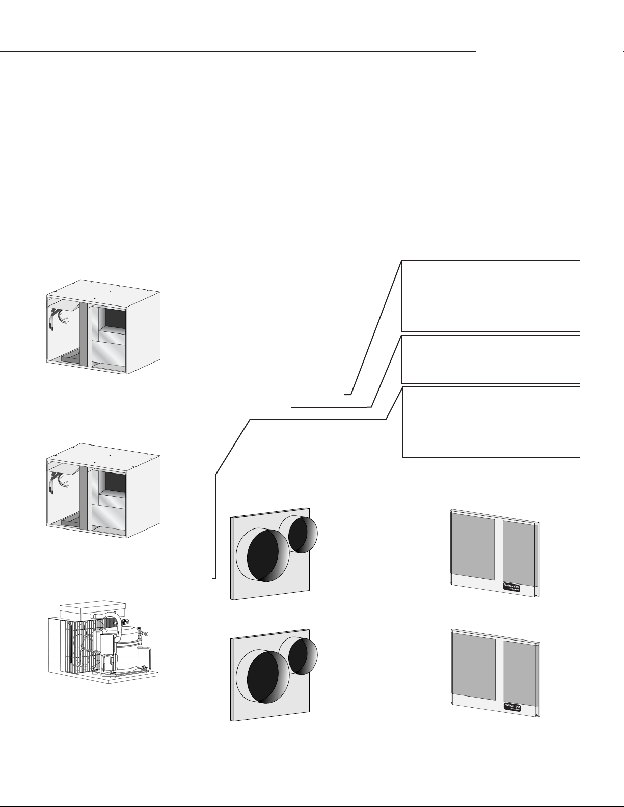
Quick Reference Guide
Wall-Mounted Evaporator Unit .......................................... 6
Fully Ducted Evaporator Unit ............................................7
Wall-Mounted Twin Specications........................................8
Fully Ducted Twin Specications .........................................9
Condensing Unit Specications ........................................ 10
Evaporator Installation
Items to Route before Installing the Evaporator Units .................... 12
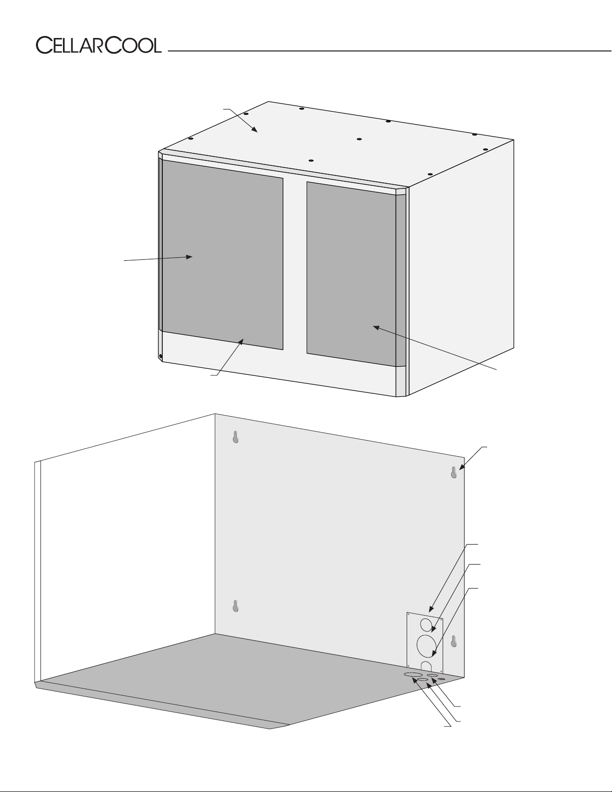
Preparing the Wall-Mounted Evaporator Units........................... 13
Installing the Wall-Mounted Evaporator Units ........................... 14
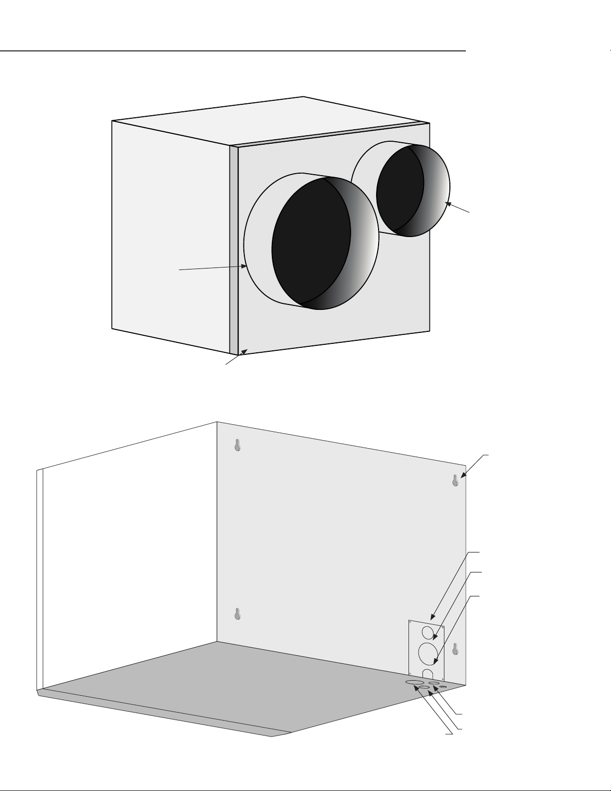
Preparing the Fully Ducted Evaporator Units ............................ 16
Installing the Fully Ducted Evaporator Units............................. 17
Ducting Overview .................................................... 18
Ducting Congurations ............................................... 19
Drain Line................................................................ 20
Liquid-Measuring Thermostat (Bottle Probe)............................... 21
Remote Display Installation............................................... 22
Wiring Diagrams
WM/FD 9000 Twin-S................................................... 28
WM/FD 9000 Twin-S Master Evaporator ................................. 29
WM/FD 9000 Twin-S Slave Evaporator .................................. 30
WM/FD 9000 Twin-S Condensing Unit .................................. 31
Copeland Cold Weather Start Kit ..........................................32
Preparing the Condensing Unit ........................................... 33
Installing the Condensing Unit ............................................ 33
Line Set Piping Diagram .................................................. 34
Installing the Ducted Plenum ............................................. 37
System Operation . . . . . . . . . . . . . . . . . . . . . . . . . . . . . . . . . . . . . . . . . . . . . . . . . . . . . . . . 42
Controller Functions...................................................... 44
CellarCool Troubleshooting Guide......................................... 50
Maintenance Schedule ................................................... 52
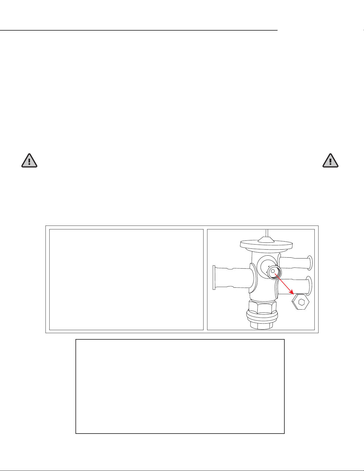
Bypass Test Procedure .................................................... 54
Technical Assistance & Accessories ........................................ 55
Installation Terms and Conditions ......................................... 56
Copyright © 2017. CellarCool. All rights reserved.
CellarCool copyrights this manual, the product design, and the design concepts, with all rights reserved. Your rights with
regard to the hardware and manual are subject to the restrictions and limitations imposed by the copyright laws of the
USA. Under copyright laws, this manual may not be copied, reproduced, translated, transmitted, or reduced to any printed
or electronic medium or to any machine-readable form, for any purpose, in whole or in part, without the written consent
of CellarCool.
Every effort has been made to ensure that the information in this manual is accurate. CellarCool is not responsible for
printing or clerical errors.
CellarCool reserves the right to make corrections or improvements to the information provided and to the related
hardware at any time, without notice.
Vinothèque and CellarCool are registered trademarks, and ECE is a trademark of CellarCool. All rights reserved.
Mention of third-party products is for informational purposes only and constitutes neither an endorsement nor a
recommendation. CellarCool assumes no liability with regard to the performance or use of these products.

Page 2 | 1-800-343-9463 WM&FD TWIN 051019
WARRANTY REGISTRATION
In order to activate the warranty of your system, the verication and operational
documentation must be completed by the certied refrigeration technician
installing your system and submitted via mail, fax, or e-mail.
Mail to:
CellarCool
ATTN: Warranty Registration
1738 E. Alpine Avenue
Stockton, CA 95205-2505
USA
Fax to:
209-466-4606
Scan and email to:
warranty@cellarcool.com
INTRODUCTION
Customer Service
Thank you for purchasing a CellarCool cooling system. We strive to provide the highest-quality products and the best possible
customer service. If you have any questions about your system, please call us at 1-800-343-9463 or visit cellarcool.com.
Using the Manual
This owner’s manual is intended to assist in the proper maintenance of the cooling system. In order to ensure the longevity of
your cooling unit, the equipment should be installed as outlined in the technician’s manual. It is also vital to establish a proper
care and maintenance schedule. Please read and review this manual carefully and keep it for future reference.
What is the CellarCool Cooling System?
The CellarCool cooling system is a specialized refrigeration system designed for one purpose only: to maintain the optimal
temperature and humidity levels conducive to the proper storage and aging of ne wines. This system produces minimal in-cellar
noise and has the most lenient exhaust requirements. An exterior housing is required for outdoor condensing unit installations.
How Does the Cooling System Work?
Similar to the air conditioning systems used for homes, the evaporator unit and condensing units are installed in separate
locations and are connected by a refrigerant line set. The evaporator portion is commonly installed in the wine cellar, with the
condensing unit is located either outside or in a remote indoor location that is ventilated. An exterior housing is required for
outdoor condensing unit installations.
Temperature Setting
The system is designed to maintain a cellar temperature of 55°F as long as the ambient temperature does not exceed 110°F.

www.cellarcool.com | Page 3
WM & FD Twin
Pump-down Cycle
CellarCool’s split systems operate on a pump-down cycle dierent from traditional air conditioners. As such, there is no wiring
between the condensing unit and evaporator unit.
CellarCool units utilize a solenoid valve on the liquid line and a low-pressure switch on the suction line. When the thermostat calls
for cooling, the solenoid valve opens, permitting the ow of refrigerant. The low-pressure switch then signals the compressor to
cycle on.
When the cellar reaches the desired temperature and the thermostat is satised, the solenoid will close, stopping the liquid
refrigerant ow to the TXV valve. The compressor will continue to operate until most of the refrigerant on the low side boils o
and is pumped through the compressor into the condenser coil and receiver. As the suction pressure falls below the pressure
control setting, the low-pressure switch will signal the compressor to cycle o. Most of the refrigerant is now stored between the
condensing unit and receiver.
…………………………………………………………………………………………………
WARNING: Do not utilize a ground fault interrupter, as it will prevent
the unit from drawing the amperage necessary to start the unit.
QUICK START GUIDE*
TXV Adjustments
A. A TXV adjustment may be necessary based on ambient temperatures in the cellar and at the condensing unit.
B. Adjust the TXV until the superheat measured at the suction line service valve is 20-30°F.
C. Under normal operation, with the wine cellar at 55°F and the ambient temperature at 85°F, the low side pressure should be
between 28-32 PSI and the high side should be between 160-180 PSI.
*Further system operation information is available on page 42.
Liquid Line King Valve
This location is used to charge the system with liquid refrigerant
and identify the high side pressure of the system.
Calculating Subcooling
To determine the subcooling of the system, calculate the dierence
between the high side pressure of the system (converted to
temperature) and the temperature of the liquid line. The temperature
of the liquid line will be taken at the outlet of the receiver.
*Saturation temp — liquid line temp
4-6°F SUBCOOLING REQUIRED FOR WARRANTY APPROVAL
TXV
The TXV is preadjusted at the factory. If the superheat is not within
20-30° at the service valve, the TXV will need to be adjusted.
ADJUSTING THE TXV
Use a ⁄” hex key to remove the cap from the TXV superheat
adjustment port. With the cap removed, insert the hex key into
the superheat adjustment port. Increase superheat by turning the
hex key clockwise. Decrease superheat by turning the hex key
counterclockwise.

Page 4 | 1-800-343-9463 WM&FD TWIN 051019
BEFORE YOU START 1-800-343-9463
1. Inspect all components prior to installation. If damage is found, please contact your distributor or CellarCool Customer
Service at 1-800-343-9463.
2. Each evaporator unit requires a dedicated 115V, 15-amp circuit. The condensing unit requires a dedicated 230V single-
phase 15-amp circuit. Use a surge protector with the unit. Do not use a GFI (ground fault interrupter) line.
3. You are REQUIRED to install a drain line to remove condensation from each evaporator unit.
4. The warranty is not active until a warranty checklist has been received, reviewed, and approved.
5. The system is intended for use in properly designed and constructed wine cellars. Hire a professional wine storage
consultant with a valid contractor’s license to build your wine cellar.
6. CellarCool requires that all split systems be installed by a certified HVAC-R technician only. NATE or equivalent is recommended.
7. It is vital that the units be set apart and oriented so that the return air from one unit does not recirculate into the supply air of
the other unit.
If you encounter a problem with your CellarCool system, please refer to the Troubleshooting Guide. If you have any further
questions or concerns, or need technical assistance, please contact CellarCool’s Customer Service at 1-800-343-9463. Please be
sure all testing has been completed prior to contacting Customer Service. Please have your results ready for your representative.

www.cellarcool.com | Page 5
WM & FD Twin
• (2) ½” x ½”90° nylon barbed tting
• (1) ½” barbed tee
• (1) Double-D strain relief
• (4) ¾” adhesive cable tie mounts
• (2) Small cable ties
• (4) #8 x 1¾” hex-head screws
RECEIVING & INSPECTING THE SYSTEM
Please leave the unit in its original box until you are ready for installation. This will allow you to move the product safely without damaging it.
When you are ready to remove the product from the box, refer to the installation instructions.
TIP: Save your box and all packaging materials. They provide the only safe means of transporting/shipping the unit.
Wall-Mounted Master Accessory Kit Box
Ducted Master Accessory Kit Box
• (1) Master WM/FD Twin
evaporator unit
• (1) Wall-mounted evaporator
installation template
Master Evaporator Box
Condensing Unit Box
• Use caution when lifting and check package for damage.
• Lift only at the designated hand-hold locations on the shipping container, or fully support the unit from underneath. A shipment may
include one or more boxes containing accessories.
• Before opening the container, inspect the packaging for any obvious signs of damage or mishandling.
• Write any discrepancy or visual damage on the bill of lading before signing.
• Allow the condensing unit to sit for 24 hours prior to start-up. The condensing unit can be placed in the installation location, piped,
and evacuated during this time.
NOTE: CellarCool units are manufactured in the USA and tested prior to shipment.
• Review the packing slip to verify contents.
• Check the model number to ensure it is correct.
• Check that all factory options ordered are listed.
If any items listed on the packing slip do not match your order information,
contact CellarCool Customer Service immediately.
Documentation bag (master):
• WM/FD 9000 Twin-S owner’s manual
• WM/FD 9000 Twin-S technician’s manual
• R-134a split system warranty checklist
• (1) Retractable bottle probe
• (1) Filter grille
• (1) Stainless steel bottle probe (50-ft cord)
• (1) Duct plenum
Accessory kit bag (master):
• KDT Plus display cable (50 feet)
• KDT Plus wall mount bracket assembly
• KDT Plus ush mount bracket assembly
• KDT Plus display assembly
• Flush mount template
• Black strain relief bushing
• Evaporator installation hardware bag
• KDT Plus hardware bag
• (1) ⁄” OD grommet
• (2) ½” nylon hole plugs
• (4) #6 x 1” PHP zinc Type A screws
• (4) 8-10 x ⁄” blue plastic screw anchors
• (2) ½” x ½”90° nylon barbed tting
• (1) ½” barbed tee
• (1) Double-D strain relief
• (4) ¾” adhesive cable tie mounts
• (2) Small cable ties
• (4) #8 x 1¾” hex-head screws
• (1) Slave WM/FD Twin evaporator unit
• (1) Wall-mounted evaporator installation
template
• (1) Evaporator installation hardware bag
Slave Evaporator Box
Check all shipped boxes for the following contents:
Wall-Mounted Slave Accessory Kit Box
• (1) Filter grille
Ducted Slave Accessory Kit Box
• (1) Duct plenum
OR
OR
• (1) Condensing unit
• (1) Condensing unit accessory kit:
- (1) ¼” lter drier
- (1) ¼” sight glass

Page 6 | 1-800-343-9463 WM&FD TWIN 051019
QUICK REFERENCE GUIDE
INSIDE CELLAR
Option 2
THROUGH THE WALL
Option 1
Knockout for wiring
Knockout for wiring
Knockout for drain line
Line set knockout
Mounting keyholes (4)
Line set knockout
Knockout for drain line
Wall-Mounted — Front / Side View
Wall-Mounted — Rear / Side View
REAR VIEW
Filter grille
Evaporator unit
Return air
Supply air

www.cellarcool.com | Page 7
WM & FD Twin
Duct plenum
Return air
Supply air
Fully Ducted — Front / Side View
INSIDE CELLAR
Option 2
THROUGH THE WALL
Option 1
Knockout for wiring
Knockout for wiring
Knockout for drain line
Line set knockout
Mounting keyholes (4)
Line set knockout
Knockout for drain line
Fully Ducted — Rear / Side View
REAR VIEW

Page 8 | 1-800-343-9463 WM&FD TWIN 051019
WALL-MOUNTED TWIN SPECIFICATIONS
Evaporator unit
Model 9000 Master Evaporator
(Fan Coil Unit)
9000 Slave Evaporator
(Fan Coil Unit)
Cellar Size Approx. 3000 cu. ft., provided cellar is fully insulated and sealed with proper vapor barrier*
BTU/h w/85°F air entering
condenser coil 7850 7850
Dimensions 16.1”L x 20.5”W x 15.5”H 16.1”L x 20.5”W x 15.5”H
Refrigerant R-134a R-134a
Voltage Rating 115V (15-amp dedicated circuit required) 115V (15-amp dedicated circuit required)
Weight (lbs) 60 60
Amps Evaporator: 1 running amp (per unit)
Compressor: LRA 35, RLA 6.5
Evaporator: 1 running amp (per unit)
Compressor: LRA 35, RLA 6.5
Line Set Liquid line ⁄”; suction line ¾” (less than 50 ft.), ⁄” (greater than 50 ft.)
Drain Line ½”ID clear plastic tubing (not provided)
Installation Evaporator units are installed in the cellar.
Thermostat Advanced digital display (50-ft. cable), liquid-temperature-measuring bottle probe (50-ft. cable)
Temp. Delta Can maintain a 55°F temperature dierential with up to 110°F condenser air intake temperature
Warranty Two-year limited warranty (parts and labor)
*Each cellar is unique and has specic cooling requirements. Heat load calculations should always be performed prior to selecting a cooling unit.

www.cellarcool.com | Page 9
WM & FD Twin
FULLY DUCTED TWIN SPECIFICATIONS
Duct plenum
Return air
Supply air
Model 9000 Master Evaporator
(Fan Coil Unit)
9000 Slave Evaporator
(Fan Coil Unit)
Cellar Size (cu. ft.) Approx. 3000 cu. ft., provided cellar is fully insulated and sealed with proper vapor barrier*
BTU/h w/85°F air entering
condenser coil 7000 7000
Dimensions
20.1”L x 20.5”W x 15.5”H 20.1”L x 20.5”W x 15.5”H
Refrigerant R-134a R-134a
Voltage Rating 115V (15-amp dedicated circuit required) 115V (15-amp dedicated circuit required)
Weight (lbs) 60 60
Amps Evaporator: 1 running amp (per unit)
Compressor: LRA 35, RLA 6.5
Evaporator: 1 running amp (per unit)
Compressor: LRA 35, RLA 6.5
Line Set Liquid line ⁄”; suction line ¾” (less than 50 ft.), ⁄” (greater than 50 ft.)
Duct Size 8” supply, 10” return (x2)
Drain Line ½”ID clear plastic tubing (not included)
Installation Evaporator units can be installed up to 25 ducted feet away.
Thermostat Advanced digital display (connected to master unit) with 50-ft. cable; liquid-temperature-measuring
bottle probe (also with 50-ft. cable)
Temp. Delta Can maintain a 55°F cellar temperature with up to 110°F condenser air intake temperature
Warranty Two-year limited warranty (parts and labor)
*Each cellar is unique and has specic cooling requirements. Heat load calculations should always be performed prior to selecting a cooling unit.

Page 10 | 1-800-343-9463 WM&FD TWIN 051019
CONDENSING UNIT SPECIFICATIONS
Model 9000 Condenser
(Air-Cooled Condensing Unit)
Dimensions 24”L x 18.98”W x 16.16”H
Refrigerant R-134a
HP 3/4
Voltage Rating 230V (15-amp dedicated circuit required)
Weight (lbs) 95
Installation Condensing unit can be installed up to 100 line feet from master evaporator unit.
Warranty Two-year limited warranty (parts and labor)

www.cellarcool.com | Page 11
WM & FD Twin
SPLIT SYSTEM CHECKLIST
In order to activate the warranty for this product, the information here must be complete and accurate. Any
incorrect or omitted information will result in a return trip by the installing technician at their cost.
NOTE: All readings need to be taken while the compressor is running.
DATA RECORDINGS
Line Set Information
A. Line set length:
B. Suction line OD:
C. Liquid Line OD:
Sub Cooling
A. Measure head pressure at liquid line king valve. Convert pressure to temp using conversion chart.
B. Temp of liquid line at king valve:
C. Complete sub cooling calculation: A – B =
Superheat Master
A. Measure suction pressure at the suction line service valve, convert to temp.
B. Measure the temperature of the suction line at the outlet of the evaporator.
C. Complete superheat calculation: B – A =
NOTE: There may be a need to adjust the TXV to get the correct superheat levels.
Bottle Probe
A. Install probe in bottle of warm water to keep system operating.
Temperature Dierential at the Evaporator
A. Measure return air and supply air temperatures at each evaporator to ensure adequate cooling of air in cellar.
Voltage and Amp Draw
A. Measure voltage to compressor and amp draw.
Charging the System
A. Fill system until bubbles dissipate from sight glass.
NOTE: Be careful not to overcharge the system.
Compressor Temperature
A. Measure temperature at bottom of compressor.
NOTE: Cool temp may indicate liquid in the compressor.
Condensation Drain Test
A. Pour water into each evaporator unit’s drain pans to ensure they drain properly.
Superheat Slave
A. Measure suction pressure at the suction line service valve, convert to temp.
B. Measure the temperature of the suction line at the outlet of the evaporator.
C. Complete superheat calculation: B – A =
NOTE: There may be a need to adjust the TXV to get the correct superheat levels.

Page 12 | 1-800-343-9463 WM&FD TWIN 051019
F
ITEMS TO ROUTE BEFORE INSTALLING THE EVAPORATOR UNITS
1. Route the refrigerant lines from each evaporator unit toward each other using ⁄”OD copper tubing for the suction line and ¼” OD
tubing for the liquid lines.
2. Join both suction lines together using a ⁄”T-tting. Install a ¾” to ⁄” reducer at the outlet of the T-tting. The remainder of the
suction line from the T-tting to the condensing unit will need to be ¾”OD copper tubing. (See page 34 for detailed piping
diagram.)
3. Join both liquid lines together using a ¼”T-tting. Install a ⁄”to ¼”reducer at the inlet of the T-tting. The remainder of the liquid
line from the T-tting to the condensing unit will need to be ⁄” OD copper tubing. (See page 34 for detailed piping diagram.)
4. Route the display cable from the desired location to the desired master evaporator unit installation location (see page 22 for more
display information).
5. Route the bottle probe cable from the desired thermostat bottle location to desired master evaporator unit installation location (see
page 21 for more bottle probe information).
6. Route the drain lines from a proper discharge location to the desired evaporator unit installation locations (see page 20 for more
drain line information).
7. Route the power cable wiring to the desired evaporator unit installation locations.
8. Route an 18-5 thermostat wire between the desired evaporator unit installation locations.
⁄” suction line
SLAVE EVAPORATOR UNIT
DISCHARGE LOCATION
CONDENSING UNIT
BOTTLE PROBE
DISPLAY CABLE
MASTER EVAPORATOR UNIT
DISCHARGE LOCATION
18-5 THERMOSTAT
WIRE
55°F
¾” suction line ⁄” liquid line
¼” liquid line
⁄” suction line
¼” liquid line
55°F
BLUE
GREEN
YELLOW

www.cellarcool.com | Page 13
WM & FD Twin
PREPARING THE WALL-MOUNTED EVAPORATOR UNITS
1. Remove the rear panel and set aside.
2. For ease of installation, remove the nine (9) screws
securing the top and remove the top.
Bottle probe connector routing location
Power
Line set
Drain line
Drain pan
• Drill
• ⁄” drill bit
• ¼” socket drill bit
• ¼” wrench
• Phillips-head screwdriver
• Tape measure
• Brazing torch
• Drywall saw
• Ladder
• Level
• Pliers
• Pencil
Required Tools:
Rear panel

Page 14 | 1-800-343-9463 WM&FD TWIN 051019
INSTALLING THE WALL-MOUNTED EVAPORATOR UNITS
1/8”
WALL
STUD
1. Locate two (2) wall studs in the desired mounting location spaced 16” on center.
2. Mark vertical lines on each stud 16” apart.
3. Mark an intersecting horizontal line at the desired height of the unit.
4. Make a mark on each stud 13½” down from the intersection of the horizontal and vertical lines.
NOTE: The top of the unit must be installed a minimum of 6” and a
maximum of 18” from the ceiling.
5. Install the four (4) supplied 1¾”hex-head
screws into the studs at the locations marked
leaving ⁄”between the wall surface and
screw head.
6. If routing through a wall, cut out an access
hole for the line set, drain line, display cable, and power wires.
7. Raise the evaporator to the installation location. Align the rear
keyholes with the mounting screws and mount the unit.
8. Using a ¼”wrench or socket, tighten the top mounting screws.
9. Using ¼”and ⁄”copper tubing, route the liquid and suction lines
through the knockouts in the housing. Be sure to extend the
tubing far enough outside of the housing to extend through the
wall if necessary.
10. Wrap both sides of the copper tubing with a wet rag to prevent
overheating.
11. To prevent oxidation, purge the system with nitrogen.
12. Braze the copper tubing to the connections on the evaporator
unit.
13. Insulate the suction line using Armaex or similar insulation.
Refer to the Wall-Mounted Evaporator Unit Installation Template for more information about mounting the wall-mounted
evaporator units.
°
F
WRAP WITH
WET RAGS

www.cellarcool.com | Page 15
WM & FD Twin
14. Using the cable ties and cable tie mounts provided, secure the
drain line to the bottom of the housing to ensure a downward
slope.
15. Route the power wire, bottle probe connector, and display cable
into the unit through the knockouts.
16. Connect the power wires according to color: connect the ground
wire to the green wire, the hot black wire to the black wire, and
the neutral white wire to the white wire.
17. Locate the thermostat wire connections inside of the master unit.
18. Connect the 18-5 wire that was routed between the evaporator
UNIT
UNIT
units according to color (yellow to yellow, red to red, and green to
green).
19. Install the supplied black strain relief to secure the power supply
wires in the housing.
20. Connect the display cable labeled“UNIT”to the wire
labeled “UNIT” located in the bottom of the evaporator
compartment.
46375
Figure 1
21. Attach the supplied bottle probe to the circular
connector on the bottom of the unit (see Figure 1).
Follow the directions on page 21 for correct installation
and placement of the bottle probe.
22. Secure all wiring neatly and as close to the left wall as
possible in order to minimize airow obstruction.
23. Seal the gaps around the display cable, bottle probe
cable, and power wire knockouts using the supplied
three-inch pieces of cork tape. (For best results, install
the cork tape inside of the unit.)
24. Repeat steps 1-24 with the second evaporator unit.
(Steps 20 and 21 do not apply to the slave unit.)
25. Follow the directions on page 37 for correct installation
of the wall mount grille.

Page 16 | 1-800-343-9463 WM&FD TWIN 051019
PREPARING THE FULLY DUCTED EVAPORATOR UNITS
1. Remove the knockouts that you will be using to
route the line set, power wires, and drain line.
2. Remove the insulation from the knockout holes.
3. For ease of installation, remove the nine (9)
screws securing the top and remove the top.
4. Follow the directions on page 22 to mount the
remote display and run the display cable to the
evaporator unit.
Power
Line set
Drain line
Bottle probe connector routing location

www.cellarcool.com | Page 17
WM & FD Twin
INSTALLING THE FULLY DUCTED EVAPORATOR UNITS
1. Using ¼”and ⁄”copper tubing, route the liquid and suction
lines through the knockouts in the housing. Be sure to extend
the tubing far enough outside of the housing to extend
through the wall if necessary.
2. Wrap both sides of the copper tubing to prevent overheating.
3. To prevent oxidation, purge the system with nitrogen.
4. Braze the copper tubing to the connections on the
evaporator unit.
5. Insulate the suction line using Armaex or similar insulation.
6. Using the cable ties and cable tie mounts provided, secure
the drain line to the bottom of the housing to ensure a
downward slope.
7. Route the power wire, display cable, and the bottle connector
through the knockouts.
8. Connect the power wires according to color: connect the
ground wire to the green wire, the hot wire to the black wire,
and the neutral wire to the white wire.
9. Locate the thermostat wire connections inside of the master
unit.
10. Connect the 18-5 wire that was routed between the
evaporator units according to color (yellow to yellow, red to
red, and green to green).
11. Install the supplied black strain relief to secure the power
supply wires and bottle probe wire in the housing.
12. Connect the display cable labeled“UNIT”to the wire
labeled “UNIT” located in the bottom of the evaporator
compartment.
UNIT
UNIT
13. Attach the supplied bottle probe to the circular
connector on the bottom of the electrical panel. (See
Figure 1.) Follow the directions on page 21 for correct
installation and placement of the bottle probe.
14. Secure all wiring neatly and as close to the left wall as
possible in order to minimize airow obstruction.
15. Seal the air gaps around the display cable, bottle probe
cable, and power wire knockouts by installing the
supplied three-inch pieces of cork tape. (For best results,
install the cork tape inside of the unit.)
16. Repeat steps 1-15 with the second evaporator unit.
(Steps 12 and 13 do not apply to the slave unit.)
17. Follow the instructions on page 37 for correct installation
of the ducted plenum.
46375
Figure 1

Page 18 | 1-800-343-9463 WM&FD TWIN 051019
DUCTING OVERVIEW
Use ductwork to connect the unit to the supply and return outlets in the wine cellar. Use only insulated ductwork to minimize
cooling losses, prevent sweating, and reduce noise. Use ductwork on the condenser section to redirect or absorb sound, bring in
outside air to the unit inlet, and/or exhaust the hot air.
NOTE: Do not exceed a total of 25 feet for each length of ductwork run and a combined total of 50 feet for both the supply and
return lengths.
Avoid crimping the flexible ducts. This reduces airflow, causing the unit to operate improperly. Be sure all ductwork and outer
surfaces in contact with the airflow are insulated and have a vapor barrier on the outside. Uninsulated supply and return ducts may
cause bare, exposed metal surfaces to sweat, further degrading the insulation and equipment cooling capacity.
Do not allow sharp turns to squeeze or decrease
the inside diameter of the flexible ducting.
General duct recommendations:
• Provide support for the flexible duct to prevent sags and bends.
• WM/FD 9000 Twin-S duct size: 8” supply and 10” return
• Stretch out the duct to make a smoother interior which reduces air resistance.
• Maximum duct length is 25 feet per evaporator unit.
• For 90° bends, use a 90° adjustable elbow.
• No more than two 90° bends on each duct. Sweep 90° bends are recommended rather than sharp 90° bends.
NOTE: For every 90° bend, the system loses 13 CFM of airflow.
NOTE: A 12” x 12” return air lter grille must be installed to prevent contaminants from entering the cooling system. Supply
duct must be insulated so it does not sweat or pick up heat.
• Generously apply duct sealant to all metal seams to fill in gaps that can leak air. Allow sealant to dry until firm to the touch
before applying fiberglass insulation.
• Do not squeeze or reduce the inside diameter of the ducts, as this will reduce airflow.
• Use short and straight ductwork where possible.
• Check that all fan blades move freely.
• Keep air paths free of loose foreign objects and debris.
• To provide adequate airflow the fan speed must be set to high when the unit is ducted.
• Locate the supply and return grilles inside the cellar to create an airflow pattern that maximizes air circulation in the room.
Avoid short circulation of the air.
• If the unit is installed through the wall, it must be mounted no more than 18 inches from the wine cellar ceiling. If the unit is
ducted, the cold air supply duct must be installed no more than 18 inches from the wine cellar ceiling.
DO NOT:
• Install through-the-wall return air grilles at floor level where they will collect dust from the floor.
• Locate the supply or return air grille where it is blocked by bottles, boxes, or cases.
Table of contents
Other Cellar Cool Kitchen Appliance manuals