CellarPro AH8500 User manual


C O N G R A T U L A T I O N S !
Thank you for purchasing a new CellarPro cooling system.
Please take a minute to read through this Owner’s Manual before you
unpack, install and turn on your Cooling Unit.
Also please look through the boxes you receive with your Air Handler
shipment to make sure you have received the correct components you
ordered and that they are all functioning before the installation.
Box 1 – Cooling unit and Accessories
Box 2 – Duct Plates and Optional Humidifier
If you have any questions about your new cooling unit, it is likely that you will find
the answers in this Owner’s Manual. We also have more information
on our website, including the latest version of the Owner’s
Manual, at www.cellarpro.com/customerservice .
If you still have questions, please don’t hesitate to contact your dealer or
CellarPro directly. We can be reached during normal business hours at
Contact Information:
CellarPro Cooling Systems
531 Mercantile Drive
Cotati, CA 94931
707.794.8000
Website: www.cellarprocoolingsystems.com

3
Table of Contents
I. Specifications, Cut Sheets, and Cellar Construction 4
II. Installation Instructions 9
III. Operating Instructions 24
IV. Troubleshooting 33
V. Limited Warranty 39
VI. Support and Data Service Sheet (Split Configuration) 40

4
I. Specifications, Cut Sheets and Cellar Construction
The following tables will provide information on the dimensions of the unit and how best
to mount or locate the various models available.
Specifications
Horizontal Self Contained
No Humdifier With Humidifier
Model Dimensions
WxDxH (inches) Weight
(lbs) Dimensions WxDxH
(inches) Weight
(lbs)
AH6500 18.6 x 37.1 x 19.3 161 33.0 x 37.1 x 18.5 181
AH8500 18.6 x 37.1 x 19.3 170 33.0 x 37.1 x 18.5 190
V
ertical Self Contained
No Humdifier With Humidifier
Model Dimensions
WxDxH (inches) Weight
(lbs) Dimensions WxDxH
(inches) Weight
(lbs)
AH6500 18.6 x 18.6 x 37.8 161 33.0 x 18.6 x 37.8 181
AH8500 18.6 x 18.6 x 37.8 170 33.0 x 18.6 x 37.8 190
Split System Evaporator Module
No Humdifier With Humidifier
Model Dimensions
WxDxH (inches) Weight
(lbs) Dimensions WxDxH
(inches) Weight
(lbs)
AH6500S 18.6 x 18.6 x 19.3 60 33.0 x 18.6 x 19.3 80
AH8500S 18.6 x 18.6 x 19.3 60 33.0 x 18.6 x 19.3 80
Split System Condenser Module
Model Dimensions WxDxH (inches) Weight
(lbs)
AH6500S 18.6 x 18.6 x 19.3 111
AH8500S 18.6 x 18.6 x 19.3 120
Cut Sheets
Note dimensions for mounting bolts and space required for installation.

5

6

7
Cellar Construction
Insulation
CellarPro cooling units are designed to be installed inside wine cellars that have proper
insulation, moisture barriers and an airtight seal from the environment outside the
cellar. Interior walls and floor
should have a minimum of R-
11 insulation, and a vapor
barrier on the warm side of
the insulation. The ceiling
should have a minimum of
R-19 insulation and a vapor
barrier on the warm side of
the insulation. Doors also
should be insulated and
tightly sealed with weather-
stripping around the
perimeter of the door.
Surface-mounted fixtures are
recommended over
recessed lighting, which can
allow air to leak into the
cellar.
It is important that all wall-
joints, doors and windows, electrical outlets and/or switches, pipes, vents and light
fixtures be sealed to prevent air and moisture from entering the cellar. If there is a leak in
the cellar, the cooling unit will build up excess condensation.
The condensate drain line and optional humidifier drain line must be connected to a
suitable drain.
Fan Speeds
Your evaporator module fan speed setting will depend on the amount of ducting and
thermal load on the wine cellar, and the resulting airflow and BTUH that is required
to cool and maintain your wine cellar at the desired temperature. Your condensing
module fan speed setting will depend on the condenser air intake temperature and the
amount of ducting, allowing for sufficient airflow to reject the heat absorbed by the cooling
system.
Ventilation
Adequate ventilation is critically important for the proper operation of your
CellarPro cooling unit, particularly on the condenser (hot) side of the cooling unit.

8
Condenser Air Exhaust/Intake.
Condensing units create significant hot air which
must be exhausted into an appropriately-sized space in order for the heat to
dissipate. If the space is constrained and/or too small, the heat will not dissipate.
In this event, the cooling unit will be forced to re-circulate its hot air exhaust and/or
the static pressure will back up the cooling unit. If this happens, the cooling unit’s
ability to create cold air inside the cellar will be compromised. In addition, the
cooling unit must be installed so that, after its installation, the condenser coils are
accessible for periodic cleaning.
Evaporator Air Exhaust/Intake.
When the warm air from the cellar passes across
the evaporator coils, heat is removed from the air, and the resulting cold air is
exhausted into the cellar. On non-ducted installations, a minimum clearance of 12” is
required from all air intake and discharge locations to maintain proper airflow.
Cold
air exhaust must be located at the highest point inside wine cellars, the cold air
exhaust eventually will drop to the bottom of the cellar. To ensure proper airflow and
reduce temperature stratification inside the cellar, the space in front of the cold air
discharge should be clear of any obstructions, including wine bottles, wine racks, etc.
Evaporator/Condensor Ducting.
CellarPro Air Handlers exhaust and return (hot
and cold side) can be ducted up to 50 equivalent feet (100' total equivalent feet
exhaust and return) with 10” diameter ducting. With our units we offer duct adaptors
and ducting that attach to either the evaporator or condenser module.

9
II. Installation Instructions
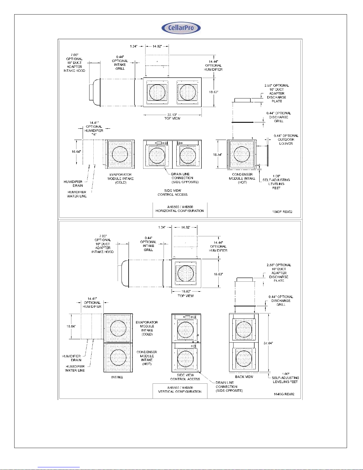
Configuration Options
The Air Handler comes in three basic configurations:
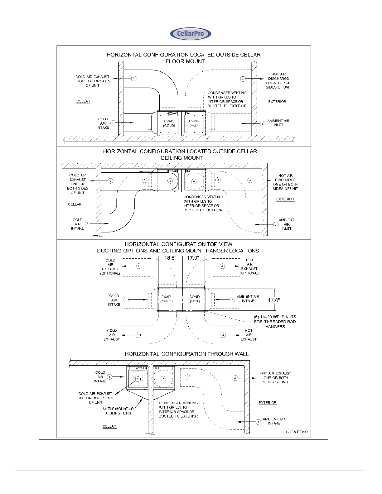
Horizontal configuration - which can be installed inside or outside the cellar.
Additionally it can be installed through the wall with a portion of the unit in the cellar
and outside the cellar.
Vertical configuration – this is the ‘stacked’ option which is a space saving approach.
Split configuration – with the evaporator in the cellar (ductless) or outside (ducted)
and with the condenser either inside or outside the house or building.
Horizontal Configuration.
Through wall: The unit is installed through the cellar wall with the evaporator module
inside the cellar, and the condenser module outside. The unit requires a mounting shelf,
sized to fit the width and depth of the unit and strong enough to support the weight of the
unit. The unit is secured to the mounting shelf using (4) 1/4-20 bolts secured to captive
nuts located in the bottom corners of the unit (note: the provided leveling feet must be
removed). The condenser can be provided with grills to vent the air, or duct adapters to
duct the intake, discharge, or both. The condenser module can also pass through the
cellar wall to an outdoor exposure by installing optional outdoor louvers to the intake and
discharge air panel openings.
Remote ducted: The unit is mounted remote to the cellar, and the evaporator module
intake and discharge air are ducted to the cellar. The condenser can be provided with
grills to vent the air, or duct adapters to duct the intake, discharge, or both. The
condenser module can also pass through an exterior wall to an outdoor exposure by
installing optional outdoor louvers to the intake and discharge air panel openings. The
unit may be floor mounted on the leveling feet provided, or flush to the floor with the
leveling feel removed. The unit may be ceiling hung using six 1/4-20 threaded rods (field
provided), attaching to captive nuts provided in the top corners and middle edges of the
unit.
Inside cellar: The unit can be mounted inside the cellar, provided that the condenser
intake and discharge are ducted to a suitably ventilated area outside the cellar.

10

11
Vertical Configuration.
Through wall: Vertical units cannot be mounted in a through wall configuration.
Remote ducted: Vertical units can be mounted remotely with the evaporator intake and
discharge air are ducted to the cellar. The condenser can be configured with grills to
vent the air provided that the location is suitably ventilated, or with duct adapters for
ducting the intake, discharge, or both to a suitably ventilated area. The unit may be
floor mounted on the provided leveling feet, or flush to the floor with the leveling feel
removed. The unit cannot be ceiling hung, and cannot be installed outdoors.
Inside cellar: Vertical units can be located inside the cellar, with the condenser intake
and discharge ducted to a suitably ventilated area outside the cellar.

12
Split Configuration.
Models in the Split Configuration can be mounted as follows, with interconnecting wiring
and refrigerant piping field provided by an experienced Refrigeration contractor:
Remote ducted: The unit is mounted remote to the cellar, and the evaporator module
intake and discharge air are ducted to the cellar. The condenser can be provided with
grills to vent the air, or duct adapters to duct the intake, discharge, or both. The
condenser module can also be located outdoors by installing optional outdoor louvers to
the intake and discharge air panel openings. The separate modules may be floor
mounted on leveling feet, or flush to the floor with the leveling feel removed. Each
module may be ceiling hung using four 1/4-20 threaded rods per module (field
provided), attaching to captive nuts provided in the top corners of the module.
Inside cellar: The evaporator module can be mounted inside the cellar as follows:
The module may be floor or shelf-mounted, or flush to the floor or shelf with the
leveling-feet removed. If shelf mounted, the evaporator module requires a
mounting shelf designed to support the weight of the module, and secured by
four 1/4-20 bolts secured to weld nuts located in the bottom corners.
The module may be ceiling hung using four 1/4-20 threaded rods (field provided),
attaching to captive nuts provided in the top corners of the module.
Condensing Units - Indoor
Condensing units can be installed remotely from the cellar in an area protected
from direct exposure to moisture and sunlight.
The area must have adequate ventilation to maintain a temperature of 110°F or
less.
If the area does not have adequate ventilation, a vent fan should be added to
supply fresh air to the space.
On units that are not ducted, a minimum of 12" of open air space is required in
front of the intake and discharge air panels.
Condensing Units - Outdoor
Both the Horizontal and Split configurations can be installed with the Condenser
module located outdoors, with optional outdoor louvers installed in the air intake
and discharge positions.
The unit is designed to operate in temperatures ranging from 0°F to 110°F.
Please note: Our compressor heater (ordered separately) is required for
temperatures below 40° F.
A minimum of 12" of open air space is required in front of the intake and
discharge air panels.
Knockouts are provided in the unit housing for field connection of conduit. The
conduit must be liquid tight and approved for outdoor use. Conduit fittings shall
be in accordance with UL 514B.

13

14
Condensate Drain Line – description and layout
The Air Handler has been designed to minimize the amount of condensation created when
cooling. The condensate that does form on the evaporator will gather in a tray and be
channeled to the drain, through a small trap, and then out through the side of the unit where
it exits via a barbed fitting.

15
Power Supply Requirements
The Air Handler is a high performance cooling system and with significant power
requirements. Each of the two sections of the unit, evaporator and condenser, requires
its own power source or cord. The amps and watts for the configurations are listed
below.
AH6500 / AH6500S Cord Connected
Evaporator Module Condenser Module System
Amps
(FLA)
@ 115V /
60HZ Breaker
Size
Power
Input
Watts
Amps
(FLA)
@ 115V /
60HZ Compressor
LRA Breaker
Size
Power
Input
Watts
Total
Power
Input
Watts
Standard 5.6 15 640 11.46 53.0 25 824 1464
With Humidifier 6.6 15 755 11.46 53.0 25 824 1579
With Heating 10.6 15 1220 11.46 53.0 25 824 1579
AH8500 / AH8500S Cord Connected
Evaporator Module Condenser Module System
Amps
(FLA)
@ 115V /
60HZ Breaker
Size
Power
Input
Watts
Amps
(FLA)
@ 115V /
60HZ Compressor
LRA Breaker
Size
Power
Input
Watts
Total
Power
Input
Watts
Standard 5.6 15 640 11.4 54.5 25 958 1598
With Humidifier 6.6 15 755 11.4 54.5 25 958 1713
With Heating 10.6 15 1220 11.4 54.5 25 958 1713
AH6500S Permanently Connected
Evaporator Module Condenser Module System
Amps
(MCA)
@ 115V /
60HZ Breaker
Size
Power
Input
Watts
Amps
(MCA)
@ 115V /
60HZ Compressor
LRA Breaker
Size
Power
Input
Watts
Total
Power
Input
Watts
Standard 3.5 15 320 17.1 53.0 25 1144 1464
With Humidifier 4.5 15 435 17.1 53.0 25 1144 1579
With Heating 11.3 15 1220 17.1 53.0 25 1144 1579
AH8500S Permanently Connected
Evaporator Module Condenser Module System
Amps
(MCA)
@ 115V /
60HZ Breaker
Size
Power
Input
Watts
Amps
(MCA)
@ 115V /
60HZ Compressor
LRA Breaker
Size
Power
Input
Watts
Total
Power
Input
Watts
Standard 3.5 15 320 16.9 54.5 25 1278 1598
With Humidifier 4.5 15 435 16.9 54.5 25 1278 1713
With Heating 11.3 15 1220 16.9 54.5 25 1278 1713
Notes:
1. Electrical ratings are for evaporator and condenser fans set on high speed.
2. Two dedicated non-GFI power supply circuits are required, one for each module.

16
System Wiring - Self Contained Configuration / Cord Connected
Models in the Horizontal or Vertical configurations are provided with two power cords
for connection to two dedicated 115V/60HZ power receptacles. Each power
receptacle must be on a separate circuit breaker, sized by model and module
according to the electrical data table. Both power cords must be connected for the unit
to operate.
System Wiring - Split Configuration / Cord Connected (Electronic Control)
Models in the Split Cord Connected configuration are provided with two power cords
for connection to two dedicated 115V / 60HZ power receptacles. Each power
receptacle must be on a separate circuit breaker, sized by model and module
according to the electrical data table. Both power cords must be connected for the unit
to operate. Field power wiring is required to connect the evaporator module to the
condenser module as shown on diagram below this section. Marked field connection
terminal blocks are provided in each module for the interconnecting wiring. Wiring
should be 18AWG minimum, copper conductors only, enclosed in conduit in
accordance with code requirements for the installation.
System Wiring - Split Configuration / Permanently Connected (Valve Only)
Models in the Split Permanently Connected configuration must be field wired to two
dedicated 115V / 60HZ circuit breakers, sized by model and module according to the
electrical data table. Field power wiring for both the evaporator module and condenser
module is shown on the diagram below. Wiring must be sized to the load, copper
conductors only, and done in accordance with code requirements for the installation.
Under this configuration the Evaporator and Condenser modules are separately
powered, and the Condenser module turns on and off based on suction pressure, as
follows:
The Evaporator module includes a factory installed liquid line solenoid valve
(LLSV), which is controlled by the Evaporator temperature controller. The
Condenser module is controlled by a low pressure switch which reacts to the suction
pressure and senses whether the LLSV is open or closed.
When the Evaporator temperature set-point is reached and the Evaporator turns off,
the LLSV closes, causing the system to pump down until the low pressure switch
shuts off the Condenser module.
When the Evaporator turns on, the LLSV opens, causing the suction pressure to
rise and activate the Condenser module.
Field power wiring is connected to both the Evaporator and Condenser module, no
interconnecting wiring is needed between the Evaporator and Condensing modules.

17

18

19
Installing Refrigeration Lines
The Evaporator and Condensing units should be piped according to the following piping
schematic:
Piping Legend
1. The 3/8"ODS liquid service valve located on Condenser Module.
2. Hermetic liquid line filter drier (shipped loose). Install with the directional flow arrow as
shown.
3. Liquid line sight glass with moisture indicator (shipped loose).
4. Liquid line refrigeration piping in accordance with Line Sizing Chart.
5. Factory installed liquid line solenoid valve (normally closed) (Valve Control
configurations only).
6. Factory installed thermostatic expansion valve.
7. Factory installed suction service valve to use for setting expansion valve superheat.
8. Insulated suction line refrigeration piping in accordance with Line Sizing Chart.
9. 5/8"ODS suction service valve located on Condenser Module.
WHEN BRAZING COPPER TUBING TO THE SERVICE VALVES, USE 95/5
SOLDER AND SOLDERING FLUX. DO NOT USE SILVER SOLDER BECAUSE
IT REQUIRES HIGHER HEAT THAT WILL DAMAGE THE SERVICE VALVES.
Line Sizing Chart
Refer to the Line Sizing Chart below for selecting the appropriate tubing size for the
length of the piping run. Note that the recommended line size may not match the
connection ports on the Condensing unit and the Evaporator. Refrigeration grade fittings
must be supplied by the installing technician to make the necessary transitions.
Transitions should be made as close to the unit as possible
. Suction line routing
must be designed to ensure oil return to the Condensing unit.

20
Split System Line Sizing Chart
Suction Line Size by Length ("ODS)
Model
Liquid Line
Size ("ODS)
Up to 100
feet
Minimum
Suction Line
Insulation
Thickness
(in)
Up to 25 feet Over 25 feet
up to 50 feet Over 50 feet
up to 100 feet
AH6500S 3/8 1/2 1/2 5/8 5/8
AH8500S 3/8 5/8 5/8 5/8 7/8
Notes:
1) Line lengths are expressed in equivalent feet = actual run length + fitting allowances.
2) Chart includes allowances for Condensing Unit Service Valves, Filter Drier, and Sight Glass.
3) Use only dehydrated refrigeration service tubing and refrigeration grade fittings.
4) Install refrigeration piping in accordance with local codes and ASHRAE guidelines.
Evacuation, Leak Detection, and Charging
Once the piping is installed, the following steps should be performed to ensure a dry
and leak-free system:
1. The Condensing unit is pre-charged with compressor oil. To avoid moisture
contamination of the oil, do not leave the service valves open to atmosphere for
more than 15 minutes.
2. Open the liquid and suction service valves on the condensing unit.
3. Valve Control only: Supply power to the Evaporator only - DO NOT connect
power to the Condensing unit. Turn on the temperature controller, which
will energize and open the liquid line solenoid valve. Verify the solenoid is
powered as indicated by the compressor icon ("snowflake") on the temperature
controller display.
4. Pressurize the system to a maximum of 150PSIG of dry nitrogen. Mark the pressure
and hold for a minimum of 1 hour. If the pressure holds, proceed to the next step,
otherwise locate and repair the leak and repeat this step.
5. Evacuate the system to a minimum of 500 microns.
If the vacuum is achieved,
proceed to the next step, otherwise locate and repair the leak and repeat from step 4.
This manual suits for next models
1
Table of contents
Other CellarPro Wine Cooler manuals