CellarPro 3000S User manual

Control the Elements
3000S / 4000S / 6000S / 8000S
Split Refrigeration Systems
Owner’s Manual

C O N G R A T U L A T I O N S !
Thank you for purchasing a new CellarPro cooling system.
Please take a minute to read through this Owner’s Manual before you unpack,
install and turn on your Cooling Unit.
If you have any questions about your new cooling unit, it is likely that you will find the
answers in this Owner’s Manual. We also have more information on our
website, including the latest version of the Owner’s Manual, at
www.cellarpro.com/customerservice .
If you still have questions, please don’t hesitate to contact your dealer or CellarPro
directly. We can be reached during normal business hours at 707.794.8000. You also
Contact Information:
CellarPro Cooling Systems
531 Mercantile Drive
Cotati, CA 94931
707.794.8000
Email: [email protected]
Website: www.cellarprocoolingsystems.com
Don’t forget to activate your warranty by completing the Support and Data
Service Sheet (pages 35-36) and fax both pages to us at 707.794.8005.

3
Table of Contents
I. Package Contents 4
II. Specifications, Cut Sheets, and Cellar Construction 5
III. Installation Instructions 10
IV. Operating Instructions 24
V. Troubleshooting 30
VI. Limited Warranty 34
VII. Support and Data Service Sheet 35

4
I. Package Contents
3000S/4000S
BOX 1:
DESCRIPTION QTY
EVAPORATOR 1
TOP MOUNTING BRACKET 2
SIDE MOUNTING BRACKET 2
WALL MOUNTING SCREWS 16
DRAIN TUBING 10 FT.
OWNERS MANUAL 1
CORK TAPE 1 FT.
DRAIN KNOCKOUT SNAP BUSHING 1
SIGHT GLASS 1
FILTER DRIER 1
BOX 2:
DESCRIPTION QTY
CONDENSING UNIT 1
BOX 3 (OPTIONAL):
DESCRIPTION QTY
CONDENSING UNIT OUTDOOR COVER 1 SET
COVER ASSEMBLY HARDWARE 1 SET
6000S/8000S
BOX 1:
DESCRIPTION QTY
EVAPORATOR 1
REAR WALL MOUNTING BRACKET 2
WALL MOUNTING SCREWS 6
DRAIN TUBING 10 FT.
OWNERS MANUAL 1
CORK TAPE 2 FT.
DRAIN KNOCKOUT SNAP BUSHING 1
HOLE PLUGS FOR ANCHOR BOLTS 2
SIGHT GLASS 1
FILTER DRIER 1
BOX 2:
DESCRIPTION QTY
CONDENSING UNIT 1
BOX 3 (OPTIONAL):
DESCRIPTION QTY
CONDENSING UNIT OUTDOOR COVER 1 SET

5
II. Specifications, Cut Sheets and Cellar Construction
Evaporator
Model Dimensions
W x D x H (inches) Weight
(lbs.) Running Amps
(with fan on “high”)
3000S 16.6 x 12.6 x 22.1
(incl. mounting brackets) 40 6.2
4000S 16.6 x 12.6 x 22.1
(incl. mounting brackets) 42 8.9
6000S 30.4 x 14.4 x 13.2
(incl. mounting bracket) 68 13.1
8000S 46.4 x 14.4 x 13.2
(incl. mounting bracket) 85 15.4
Condensing unit - Indoor
Condensing unit - Outdoor
Model Dimensions
W x D x H (inches) Weight
(lbs.) Dimensions
W x D x H (inches) Weight
(lbs.)
3000S 13.5 x 18.9 x 9.1 42
19.4 x 23.3 x 18.8
(with cover)
73
4000S 13.5 x 18.9 x 10.3 45 76
6000S 13.9 x 18.9 x 11.9 54 85
8000S 16.8 x 20.8 x 14 76 107

6
Evaporator Cut Sheets

7
Condensing Unit Cut Sheets

8
Insulation
CellarPro cooling units are designed to be installed inside wine cellars that have
proper insulation, moisture barriers and an airtight seal from the environment
outside the cellar. Interior walls and floor should have a minimum of R-11
insulation, and a vapor barrier
on the warm side of the
insulation. The ceiling should
have a minimum of R-19
insulation and a vapor barrier
on the warm side of the
insulation. Doors also should
be insulated and tightly
sealed with weather
stripping around the
perimeter of the door.
Surface-mounted fixtures
are recommended over
recessed lighting, which can
allow air to leak into the
cellar.
It is important that all walls,
joints, doors and windows, electrical outlets and/or switches, pipes, vents and
light fixtures be sealed to prevent air and moisture from entering the cellar. If there is
a leak in the cellar, the cooling unit will build up excess condensation.
We strongly recommend that the overflow drain line (shipped loose with the cooling
unit) be connected to the overflow drain (as shown in the installation section). In
addition, we recommend turning on the electric heating element to burn off excess
condensate that accumulates in the stainless steel pan during the initial cooling of
the cellar and during high run-times, as well as in high-humidity environments.
Fan Speeds
Your fan speed setting will depend on the thermal load on the wine cellar, and
the resulting BTU that is required to cool and maintain your wine cellar at the
desired temperature.
Ventilation
Adequate ventilation is critically important for the proper operation of your
CellarPro cooling unit.

9
Outside the Cellar
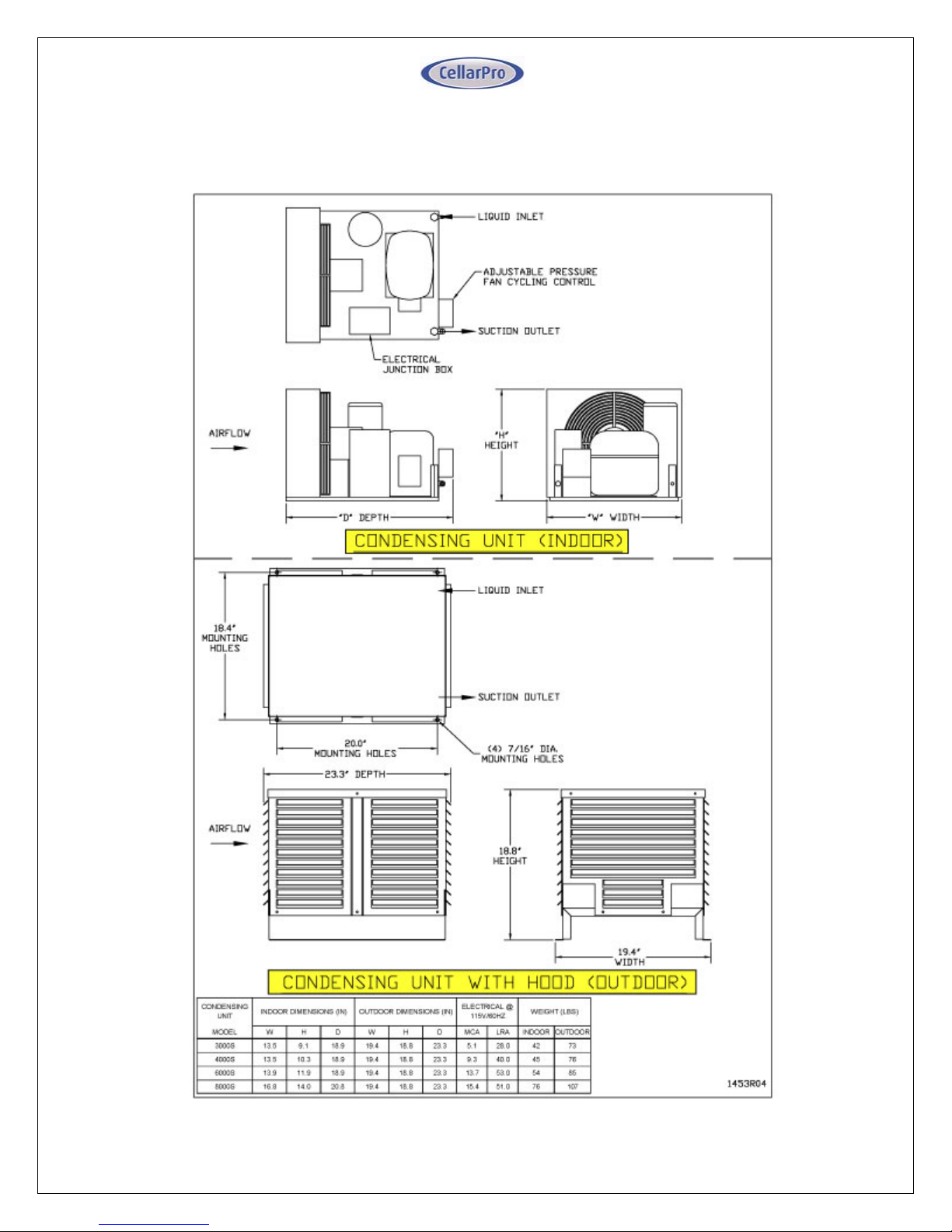
Condensing unit Air Exhaust. Condensing units create significant hot air which
must be exhausted into an appropriately-sized space in order for the heat to
dissipate. If the space is constrained and/or too small, the heat will not dissipate.
In this event, the cooling unit will be forced to re-circulate its hot air exhaust
and/or the static pressure will back up the cooling unit. If this happens, the
cooling unit’s ability to create cold air inside the cellar will be compromised.
Condenser Air Intake. The condenser coils require access to cool air in order for
the cooling unit to produce cold air. In addition, the cooling unit must be installed
so that, after its installation, the condenser coils are accessible for periodic
cleaning.
The Condensing unit cannot be ducted.
Inside the Cellar
Evaporator Air Intake
.
When the warm air passes across the evaporator coils,
heat is removed from the air, and the resulting cold air is exhausted into the cellar.
To ensure proper airflow, minimum clearance of 12” is required in front of the
cooling unit.
Evaporator Air Exhaust.
Cold air is exhausted at the top front of the cooling unit.
Because CellarPro cooling units are located at the highest point inside wine
cellars, the cold air exhaust eventually will drop to the bottom of the cellar. To
ensure proper airflow and reduce temperature stratification inside the cellar, the
space in front of the cold air discharge should be clear of any obstructions,
including wine bottles, wine racks, etc.
Ducting. CellarPro Evaporators cold air exhaust and return can be ducted with a
hood up to 50 equivalent feet with 8” diameter ducting, or 100 equivalent feet with
our auxiliary fan and 8” diameter ducting. We offer a duct kit (sold separately) with
two fitting that attach to the front of the cooling unit and can be ducted.
We also offer a remote control panel kit that can be installed remotely (up to 10
feet) from the cooling unit, either inside or outside the cellar, and a bottle probe
(10 foot cord) that can be plugged into the cooling unit.

10
III. Installation Instructions
Installation Instructions
Split System piping and wiring must be installed by a qualified Refrigeration
Technician in accordance with local and national code requirements.
Condensing Unit Installation
Indoor Units
Condensing units can be installed remotely from the cellar in an area protected
from direct exposure to moisture and sunlight.
The area must have suitable ventilation to maintain an ambient temperature of
110°F or less.
If the area does not have adequate ventilation, a vent fan should be added to
supply fresh air to the space (suggested 600CFM).
A minimum of 12" of open air space is required in front of the condenser coils.
Indoor units can be installed with the optional outdoor hood if additional
mechanical protection is desired.
A minimum of 12" of open air space around the perimeter of the outdoor hood
is required.
Outdoor Units
Condensing units must be installed with the outdoor hood if the unit will be
located outdoors.
The unit is designed to operate in temperatures ranging from 0°F to 110°F.
Please note: An optional compressor heater is required for temperatures
below 40°F.
A minimum of 12" of open air space around the perimeter of the outdoor hood
is required.
Evaporator Unit Installation
As warm air rises to the top of the cellar, the cooling unit pulls the warm air
through the evaporator coil and removes the heat from the warm air. Once
cooled, the cold air is discharged from the front of the cooling unit and circulates
through the cellar. Therefore, we recommend mounting the evaporator as close
to the ceiling as possible inside the cellar.

11
3000S / 4000S
Side mounting brackets are provided for mounting the evaporator flush to a wall
inside the cellar. Optional top and bottom brackets (non-load bearing) are
available upon request.

12
6000S / 8000S
Wall hangers are used to mount these split systems. First, wall brackets are
attached to the wall, and then the evaporator slides onto the brackets. After the
evaporator is installed, two bottom nuts must be installed on the recessed anchor
studs.

13
Condensate Drain Line
The condensate drain line should drop, then rise (but stay below the height of the
fitting), and then drop again into a drain or bucket. Then, fill the trap with water. The
condensate trap will allow any excess moisture inside the Evaporator to
overcome the static pressure and flow out of the drain line.

14
Power Supply Requirements
EVAPORATOR CONDENSING UNIT
SPLIT
SYSTEM FAN AMPS @ 115V/60HZ POWER INPUT WATTS UNIT AMPS @
115V/60HZ
POWER
INPUT
MODEL MCA HIGH MED LOW HIGH MED LOW MCA LRA WATTS
3000S 1.3 1.0 0.8 0.7 107 84 70 6.4 28.2 442
4000S 1.7 1.4 1.1 1.0 159 122 107 9.2 40.0 591
6000S 2.6 2.1 1.7 1.4 214 168 140 13.5 53.0 922
8000S 3.5 2.8 2.2 1.9 318 244 214 15.4 51.0 1028
NOTES:
SPLIT
SYSTEM SYSTEM AMPS POWER INPUT WATTS
MODEL MCA LRA HIGH MED LOW
3000S 7.4 28.0 549 526 512
4000S 10.6 40.0 750 713 698
6000S 15.6 53.0 1136 1090 1062
8000S 18.2 51.0 1346 1272 1242
NOTES:
Option A: Dual Power / Valve Control
Option B: Single Power / Electronic Control
1) A 15 amp dedicated circuit breaker (non GFI) is recommended for 3000S and 4000S systems.
2) A 25 amp dedicated circuit breaker (non GFI) is recommended for 6000S and 8000S systems.
1) Separate 115V / 60HZ power supplies are required for the Evaporator and the Condensing Unit.
2) A 15 amp circuit breaker is recommended for all Evaporator models.
3) A 15 amp dedicated circuit breaker (non GFI) is recommended for 3000S and 4000S Condensing
Units.
5) A 25 amp dedicated circuit breaker (non GFI) is recommended for the 8000S Condensing Unit.
4) A 20 amp dedicated circuit breaker (non GFI) is recommended for the 6000S Condensing Unit.
SINGLE 115V 60HZ POWER SUPPLY TO/FROM
EVAPORATOR

15
System Wiring – Option A: Dual Power / Valve Control
Under this configuration the Evaporator and Condensing units are separately
powered, and the Condensing unit turns on and off based on suction pressure, as
follows:
The Evaporator includes a factory installed liquid line solenoid valve
(LLSV), which is controlled by the Evaporator temperature controller. The
Condensing unit is controlled by a low pressure switch which reacts to the
suction pressure and senses whether the LLSV is open or closed.
When the Evaporator temperature set-point is reached and the Evaporator
turns off, the LLSV closes, causing the system to pump down until the low
pressure switch shuts off the Condensing unit.
When the Evaporator turns on, the LLSV opens, causing the suction
pressure to rise and activate the Condensing unit.
Field power wiring is connected to both the Evaporator and Condensing units, no
interconnecting wiring is needed between the Evaporator and Condensing unit.
Evaporator Field Power Wiring:
Connect line lead to Evaporator terminal "L"
Connect neutral lead to Evaporator terminal "N"
Connect power ground to grounding lug on Evaporator
Condensing Unit Field Power Wiring:
Connect line lead to Condensing unit terminal "L1"
Connect neutral lead to Condensing unit terminal "L2"
Connect power ground to grounding lug on Condensing unit.

16
Wiring Diagram – Option A: Dual Power / Valve Control

17
System Wiring – Option B: Single Power / Electronic Control
Under this configuration, only the Evaporator is powered, and the Condensing unit
is wired to the Evaporator by connecting:
"L" on the Evaporator to "L1" on the Condensing unit
"N" on the Evaporator to "L2" on the Condensing unit
Ground lug on the Evaporator to the grounding stud on the Condensing unit.
With optional crankcase heater: Run a separate lead connecting “L” on
Evaporator “C” on Condensing Unit.

18
Installing Refrigeration Lines
The Evaporator and Condensing units should be piped according to the following
piping schematic:
Piping Legend
1. The 3/8"ODS liquid service valve is located on the Condensing unit.
2. Hermetic liquid line filter drier (shipped loose). Install with the directional flow
arrow as shown.
3. Liquid line sight glass with moisture indicator (shipped loose).
4. Liquid line refrigeration piping in accordance with Line Sizing Chart.
5. Factory installed liquid line solenoid valve (normally closed) (Dual
Power/Valve Control configurations only).
6. Factory installed thermostatic expansion valve. Bulb must be attached to a
horizontal run of the suction line after brazing the field suction connection,
and insulated with the supplied cork tape.
7. Factory installed suction service valve to use for setting expansion valve
superheat.
8. Insulated suction line refrigeration piping in accordance with Line Sizing
Chart.
9. 5/8"ODS suction service valve located on Condensing unit.
Line Sizing Chart
Refer to the Line Sizing Chart below for selecting the appropriate tubing size for
the length of the piping run. Note that the recommended line size may not match
the connection ports on the Condensing unit and the Evaporator. Refrigeration
grade fittings must be supplied by the installing technician to make the necessary
transitions. Transitions should be made as close to the unit as possible.
Suction line routing must be designed to ensure oil return to the Condensing unit.

19
Split System Line Sizing Chart
Model
Liquid Line
Size ("ODS)
Up to 100
feet
Minimum
Suction Line
Insulation
Thickness
(in)
Up to 25 feet Over 25 feet
up to 50 feet Over 50 feet
up to 100 feet
3000S 1/4 1/2 1/2 1/2 1/2
4000S 3/8 1/2 1/2 1/2 1/2
6000S 3/8 1/2 1/2 5/8 5/8
8000S 3/8 5/8 5/8 5/8 7/8
Notes:
1) Line lengths are expressed in equivalent feet = actual run length + fitting allowances.
2) Chart includes allowances for Condensing Unit Service Valves, Filter Drier, and Sight Glass.
3) Use only dehydrated refrigeration service tubing and refrigeration grade fittings.
4) Install refrigeration piping in accordance with local codes and ASHRAE guidelines.
Suction Line Size by Length ("ODS)
Evacuation, Leak Detection, and Charging
Once the piping is installed, the following steps should be performed to ensure a
dry and leak-free system:
1. The Condensing unit is pre-charged with compressor oil. To avoid moisture
contamination of the oil, do not leave the service valves open to atmosphere
for more than 15 minutes.
2. Open the liquid and suction service valves on the condensing unit.
3. a. Dual Power Source / Valve Control: Supply power to the Evaporator only
- DO NOT connect power to the Condensing unit. Turn on the
temperature controller, which will energize and open the liquid line
solenoid valve. Verify the solenoid is powered as indicated by the
compressor icon ("snowflake") on the temperature controller display.
b. Not applicable

20
4. Pressurize the system to a maximum of 150PSIG of dry nitrogen. Mark the
pressure and hold for a minimum of 1 hour. If the pressure holds, proceed to
the next step, otherwise locate and repair the leak and repeat this step.
5. Evacuate the system to a minimum of 500 microns. If the vacuum is
achieved, proceed to the next step, otherwise locate and repair the leak and
repeat from step 4.
6. Disconnect the vacuum pump, but leave the system under vacuum. Use a
charging scale to accurately weigh in the refrigerant. Charge liquid R-134a
refrigerant through the liquid service valve according to the charge pounds
indicated in the "System R-134a Charge Guidelines" chart below. Additional
refrigerant may need to be added, as detailed in the next step.
7. Warm the bottom shell of the compressor above the ambient temperature for
30 minutes to drive excess refrigerant out of the compressor oil. Connect
power to the Evaporator and Condensing unit, and activate the system.
Check that the sight glass is clear when the compressor is running. The
condensing temperature must be above 105°F (135.0 PSIG) when inspecting
for a clear sight glass. In a low ambient environment, it may be necessary to
block off the condenser air intake to force the condensing temperature higher.
If the sight glass is not clear, slowly add vapor refrigerant though the suction
service valve.
8. With a clear sight glass, adjust the superheat on the thermostatic expansion
valve to 10°F +/- 2°F, as measured at the suction access valve located in the
Evaporator.
9. Once the superheat is adjusted, ensure the condenser face airflow is
unrestricted and allow the system to balance for 30 minutes.
10.Check the suction superheat at the compressor using the access port on the
suction service valve. A minimum superheat of 20°F is required at this
location. If it is below 20°F, recheck the thermostatic expansion valve
superheat and increase as necessary to ensure a 20°F superheat at the
compressor.
11.Adjust the fan cycling control (located on the Condensing unit) so that the
condenser fan cuts-out at approximately 90°F (104.5 PSIG), and cuts-in at
120°F (171.0 PSIG).
Other manuals for 3000S
1
This manual suits for next models
3
Table of contents
Other CellarPro Wine Cooler manuals