CEMO Trolley 100 L AdBlue User manual

138.1519.303 / 11.13 / Ec CEMO GmbH
In den Backenländern 5•D-71384 Weinstadt
Tel.
+49 7151 9636-0
• Fax
+49 7151 9636-98
•www.cemo.de
Dieseltrolley100 l
mit Handpumpe
E
Sistemade depósito diésel móvil Español 31-37
compuesto deun depósitode PEde paredsencilla
conbomba manual K10C
I
Impianto mobile dirifornimento Diesel Italiano 24-30
costituitoda unserbatoio PEmonoparete
conpompamanualeK10C
F
Station deravitaillement gasoilmobile Français17-23
constituéed’un réservoir en PE à uneparoi,
équipéed’unepompemanuelle K10C
GB
Mobile dieselllingstation English 10-16
consisting of a single-wall PEtank withK10C handpump
D
Mobile Dieseltankanlage Deutsch3-9
bestehend aus einwandigem PE-Tank mit Handpumpe K10C

E
Manual deinstrucciones
•Entregaral usuario
•Leersiempre antes dela puestaen servicio
•Conservar parausofuturo
I
Istruzioni per l‘uso
•daconsegnare all‘operatore
•leggere prima della messa infunzione
•conservare l’opuscolo per poterloconsultare infuturo
F
Manuel d’utilisation
•à remettre à l’utilisateur
•à lire impérativementavantla miseen service
•à conserver pourpouvoirle consulter ultérieurement
GB
Operating Instructions
•provide to operator
•mustbe readbefore using the equipmentfortherst time
•retain for futureuse
2
D
Betriebsanleitung:
•dem Bediener aushändigen
•vor Inbetriebnahmeunbedingt lesen
•für künftige Verwendung aufbewahren

D
3
Inhalt
1. Allgemeines
1.1 Sicherheit
1.1.1 Instandhaltung und
Überwachung
1.1.2 Originalteile verwenden
1.1.3 Bedienung der Tankanlage
1.1.4 Warnhinweise an der Tankanlage
1.2 BestimmungsgemäßeVerwendung
1.2.1 Dieseltrolley nach
ADR 1.1.3.1 c)
1.2.2 Zusammenfassung
1.3 Sachwidrige Verwendung
2. Technische Daten
2.1 Tank
2.2 Pumpe
2.3 Zapfventil
3. Aufbau
4. Erstinbetriebnahme
5. Betrieb
5.1 Lagerung
5.2 Bewegen des Dieseltrolley
5.3 Verladen
5.4 Transportieren
5.5 Tank befüllen
5.6 Betanken
6. Wartung und Inspektion
6.1 Sicherheitsmaßnahmen
6.2 Wartungs- und Inspektionstabelle
7. Stilllegung / Dekommissionierung
8. Gewährleistung
1. Allgemeines
DiemobileDieseltankanlageentspricht dem
StandderTechnik und den anerkanntensicher-
heitstechnischen Regeln.
DieTankanlage darfnur ineinwandfreiem
technischem Zustandin der vom Hersteller
ausgelieferten Ausführungverwendetwerden.
AusSicherheitsgründenistes nicht gestattet,
Umbautenan der Tankanlage vorzunehmen
(außer dem Anbau von Zubehör, das speziell
durchdenHersteller bereitgestellt wird).
1.1Sicherheit
Jede Tankanlagewird vor Auslieferungauf
Funktion und Sicherheit geprüft.
BeibestimmungsgemäßerVerwendungistdie
Tankanlagebetriebssicher.
BeiFehlbedienungoder Missbrauchdrohen
Gefahrenfür
•Leib und Leben des Bedieners,
• die Tankanlageundandere Sachwertedes
Betreibers,
•dieFunktion der Anlage.
Um Gefahren für Personen,Tiere und
Sachen zuvermeiden,lesenSiebitte vor
demersten Betreiben der Tankanlage
diese Betriebsanleitung, insbesondere alle
Sicherheitshinweise.
VergewissernSiesich:
• dassSieselbst alleSicherheitshinweise
verstanden haben,
• dassderBediener der Tankanlageüber die
Hinweise informiertistundsieverstanden hat,
• dassdieBetriebsanleitung zugänglichistund
beiderTankanlageausliegt.
1.1.1Instandhaltung und Überwachung
DieTankanlage mussturnusmäßigaufihren
sicheren Zustandüberprüftwerden.
Diese Überprüfungumfasstinsbesondere
• SichtprüfungaufLeckagen (Dichtheit von
Befüllschlauch und Armaturen),
•Funktionsprüfung,
• Vollständigkeit / Erkennbarkeit der Warn-,
Gebots-undVerbotsschilderan der Anlage,
• die vorgeschriebenen turnusmäßigen
Inspektionen (Details siehe Kapitel 6).

D
4
1.1.2Originalteileverwenden
Verwenden Sie bitte nur Originalteiledes
Herstellersoder von ihm empfohleneTeile.
Beachten Sie auchalleSicherheits- und
Anwendungshinweise,diediesenTeilen
beigegebensind.
Dies betrifft
• Ersatz-undVerschleißteile,
•Zubehörteile.
1.1.3BedienungderTankanlage
Um Gefahren durch falscheBedienungzu ver-
meiden,darf die Tankanlage nur von Personen
bedient werden,die
•dieBetriebsanleitunggelesenhaben,
• ihre Fähigkeiten zum Bedienen nachgewiesen
haben,
• mit der Benutzung beauftragt sind.
iWichtig!
DieBetriebsanleitungmuss fürjeden
Benutzer gut zugänglich sein.
1.1.4Warnhinweisean der Tankanlage
DieWarnschilder anderAnlagemüssenstets
angebrachtundlesbar sein.
VomHersteller angebrachteSchilder:
Verbot von Feuer und offenem
LichtundRauchen
Anbringung:
an Tank-Vorderseite
1.2Bestimmungsgemäße Verwendung
DiesemobileDieseltankstelle ist zulässig
gemäßADR1.1.3.1a) (Privatgebrauch, max.60l
Inhalt) und 1.1.3.1 c)(Handwerkerregelung).
DerSammel-, Transport- und Entnahmebehälter
istauch zum Aufstellenim Freiengeeignet
(Umgebungsbedingungen Kapitel 2.1 beach-
ten!).
Eine bestimmungsgemäße Verwendungbetrifft
z.B.(vorzugsweise)folgendeFlüssigkeiten:
-Dieselkraftstoff/Heizöl
-Biodiesel
1.2.1Dieseltrolleynach ADR1.1.3.1c)
GemäßADR1.1.3.1c) (in Deutschland sog.
„Handwerkerregelung“)dürfenauch mit
Behältern ohneADR-ZulassungGefahrgut-
transporte durchgeführtwerden.
FürBehälternach ADR1.1.3.1c) gilt:
• Transportnur für direkten Verbrauch mit
Eigenbetankung (d.h., Anfahrennur einer
Betankungsstelle und Durchführungder
Betankung nicht durch Dritte),
•keine Bezettelung (Aufkleber)erforderlich,
•keine Ausrüstungspflicht mit Feuerlöschgerät,
•kein Begleitpapier erforderlich,
• zulässigerBehälterinhalt:max. 450l,es gilt
ebenfalls die sog.„1000-Punkte-Regel“
•keine Wiederholungsprüfungerforderlich,
•keine Lebensdauerbeschränkung.
1.2.2Zusammenfassung
Eine andere Verwendungistnichtbestimmungs-
gemäß!
AusSicherheitsgründen ist esauch nicht
gestattet,Umbautenan der Tankanlage vorzu-
nehmen (außer dem Anbau von Zubehör,das
spezielldurchdenHersteller bereitgestellt wird).
ZurbestimmungsgemäßenVerwendunggehört
auch das BeachtenallerHinweise indieser
Betriebsanleitung,
1.3Sachwidrige Verwendung
iWichtig!
Eine sachwidrige Verwendung ist dem-
zufolge auchdasNichtbeachtender
Hinweisedieser Betriebsanleitung.
D e s w e i t e r e n :
• Nichtbeachtungder RegelungenderADR,
einschließlich1.1.3.1 c), und jeweils gültiger
nationaler Bestimmungen
• LagerungundTransport von anderen als den
unterbestimmungsgemäßerVerwendung
genannten Flüssigkeiten, z.B.:Bioethanol,
Chemikalien,Öle(Schmier-, Hydraulik-,
Pflanzenöl)
D
5
2. TechnischeDaten
2.1Tank
Länge [cm]: 100
Breite [cm]: 59
Höhe [cm]:43
Leergewicht[kg]:20
Nennvolumen [l]:100
Gesamtgewicht [kg]: 105
Umgebungsbedingungen:
Einsatztemperaturen: -10 °Cbis +40°C
3. Aufbau
aSchraubverschlussbelüftet
bKugelhahn Entnahmeleitung
cHandpumpe
dZapfschlauch
eZapfventil
fSchlauchhalter-Scheibe
gBolzenknopfriegel
hZapfventilhalterung
iTransportgriff
jGriffmulde
kVertiefung für Spanngurte
lSchlauchhalter-Distanzstück
2.2 Pumpe
Handpumpe K10CCEMO liegend:
DieK10C CEMOliegend ist eine handbe-
triebene Pumpe zur FörderungundAbgabe
von Kraftstoffenundähnlichen Medienaus
Vorratsbehältern.
DiePumpe ist einfachwirkend,mit einer
Förderleistung von ca.0,25 l/Hub.
FürdieFunktion der Pumpe ist außerhalbauf
derSaugseite ein Rückschlagventil eingebaut.
Flüssigkeitstemperatur:-10°C bis +40°C
2.3Zapfventil
Anschluss: 1"Innengewindemit Drehgelenk
Zapfrüssel: Ø 20 mm
i
c
e
h
b
g
a
d
l
k
f
j

D
6
4. Erstinbetriebnahme
1. DiedenTankpapierenbeigepackten
Aufkleberan den Stirnseiten dauerhaft fest
aufkleben.
UN 1202
(für Diesel)
Gefahrzettel
3. MontagedesZapfschlauches
Knickschutzfeder überdas Schlauchende
schieben
Achtung
beiderHandhabung
derFederbandschelle
VERLETZUNGSGEFAHR
Den Kunststoff-Halteclip (blaues Kunststoffteil)
nur anderendgültigen Position der Federband-
schelleentfernen!
Federbandschelle überdieKnickschutzfeder
schieben.
SchlauchaufdiePumpenausgangsöffnung
schieben.
Kunststoff-HalteclipderFederbandschelle
entfernen.
Zapfventil mit der Schlauchtülleverschrauben
Schlauchaufwickeln.
Zapfventil indieintegrierteAufnahmeeinführen
undüber den Bolzenknopfriegel sichern.
4. Dieseltrolleyin horizontale Lagebringen und
Schraubverschlussaentfernen.
Tank befüllen
iWichtig!
VerwendenSiedazu bitte unbedingt ein
Automatik-Zapfventil, umeinÜberlaufen
zu vermeiden.
2. Dieuntere Schlauchhalter-Scheibe mit
denSchlauchhalter-Distanzstücken(starr)
unddenSchrauben(M6x40)am Behälter
befestigen.
DieDämpfer(3 Stück) mit dem Behälter
verschrauben.
DieSchlauchhalter-Scheibeobenmit den
Dämpfern verschrauben(M6 x10).
Distanzstück
starr Dämpfer

D
7
5. Probebetankungdurchführen wie unter
Abschnitt5.6 beschrieben,jedoch Zapfventil
in die nochgeöffnete Befüllöffnunghalten.
6. Befüllöffnungmit dem Schraubverschluss
verschließen.
DenBelüftungsverschluss imSchraub-
verschlussebenfalls verschließen.
DieTankanlage ist nun betriebsbereit.
Belüftungs-
verschluss
Schraub-
verschluss
5. Betrieb
5.1Lagerung
Achtung!
Sachschäden(Verformung) des
Tanksdurchstarke Erwärmung
oder mechanische Überlastung.
• SetzenSiedenhochwertigen Kunststofftank
wederzumTransportaufdemFahrzeug noch
beiderAufbewahrunglängere Zeit direktem
Sonnenlicht aus.
Geeignete Lagerbedingungen:
• Umgebungstemperatur:-10°Cbis +40°C
(bei Lagerungim Freienz. B.abdecken)
• Fußboden:eben und glatt
(ohnespitze Erhebungen)
5.2Bewegendes Dieseltrolley
iWichtig!
Der vollständig befüllte
Dieseltrolley ist schwer.
DerDieseltrolleykann überdieluftbereiften
Räder einfach transportiertwerden.
Beachten Sie,dassbeigroßen Steigungen
undGefällen erhebliche Hangabtriebskräfte
entstehen.
5.3Verladen
iWichtig!
Der vollständig befüllteDieseltrolley ist
schwer,nichtversuchendiesen alleine
anzuheben.
DerleereDieseltrolleykann mittels Griffmuldenj
im Bereich der Räder sowie dem Transportgriff
verladen werden.Beachten Sie dabei das
Gewichtderleeren Anlage von 20kg.
5.4Transportieren
Beachten Sie beim Transportdieeinschlägigen
Vorschriften für TransportundLadungs-
sicherung, insbesondere
• Straßenverkehrs(zulassungs)ordnungdes
jeweiligen Landes,
• CEN 12195 Teil 1-4 für Berechnung und
Zurrmittel.
BenutzenSiezurBefestigungmittels geeigneter
Spanngurteaufdem Transportfahrzeug die inte-
grierten Vertiefungen kim Tankzum Einlegen
der Spanngurte.
iWichtig!
Formschluss vor Kraftschluss!
VersuchenSiein erster Linie die
Anlage formschlüssig zuverladen(z.B.durch
Anschlagen andieBordwand).
Zu hoheZurrkräfte können den Tankverformen
undsomitbeschädigen.
5.5Tank befüllen
Dieseltrolley inhorizontaleLage bringen und
Schraubverschlussentfernen.
Betanken des Behältersüber die Befüllöffnung
mittels selbsttätig schließendem Zapfventil.
Nach BetankenBefüllöffnungmit Schraub-
verschlussawieder dicht verschließen.
DenBelüftungsverschlussim Schraubver-
schluss ebenfalls verschließen.
VerunreinigungendesBehälters durch das
Betanken mit einem trockenen Tuchsofort
entfernen.
Bild 01

D
8
5.6Betanken
DasBetanken ist sowohlin horizontaler als
auch invertikaler Behälterlage möglich.
Ein besseresAnsaugverhaltenundeine
bessere Restentleerungwird inhorizontaler
Behälterlageerzielt.
Beachten Sie,dasszu hoheZugkräfte
am SchlauchdenDieseltrolleyausder
vertikalen Lagekippen können.
Belüftungsverschluss(siehe Bild 01)im
Schraubverschluss öffnen.
Kugelhahn bder Entnahmeleitungöffnen.
Bolzenknopfriegel öffnen und Zapfventil voll-
ständigin den zubefüllenden Behälter /Tank
stecken.
Zapfventil ebetätigen.
Hebel der Handpumpe inhorizontaler
Richtung vor-undzurückbewegenund
Betankungsvorgang beginnen.
iWichtig!
BeaufsichtigenSieden
Betankungsvorgang ständig.
6. WartungundInspektion
6.1Sicherheitsmaßnahmen
iWichtig!
Schutzbekleidung muss vom Betreiber
bereitgestellt werden.
Werdarf Wartungs-undInspektionsarbeiten
durchführen?
NormaleWartungsarbeiten dürfen vom
Bedienpersonal durchgeführt werden.
Handpumpenur bei geöffnetemBelüftungs-
verschlussundgeöffnetemKugelhahn
betreiben!
Nach dem Betankungsvorgang:
Zapfventil schließen und abtropfen lassen.
Zapfschlauchaufwickeln.
Zapfventil indieintegrierte Zapfventilhalterungh
einlegenundmit Bolzenknopfriegelgsichern.
Kugelhahn der Entnahmeleitungbschließen.
Belüftungsverschluss imSchraubverschluss
schließen (Bild 01).
6.2Wartungs-und Inspektionstabelle
Intervall Baugruppe Tätigkeit
BeiBedarfTankanlage AußenseiteVon anhaftendem Schmutzbefreien
monatlich BehälterOptischePrüfungaufBeschädigung
monatlich Leitungssystem Schläuche auf Risse und Porosität prüfen, Armaturen auf
Leckageprüfen (defekteTeile tauschen)
monatlich Transporträder Luftdruckprüfen (2bar)
jährlich Filter Reinigen
Kugelhahn
Dichtung
Filter
Dichtung
Entnahmerohr
Zum ReinigendesFiltersden Kugelhahn vom Entnahmerohrlösen.
Reifendruck der Transporträder 2 bar.
Eine regelmäßige Wartung der Handpumpe ist nicht notwendig.
DerFilter befindetsich zwischenzwei Dichtungenin der Verschraubung
des Kugelhahnesmit dem Entnahmerohr.

D
9
7. Stilllegung /
Dekommissionierung der
Tankanlage
• Zunächst Tank vollständigentleeren
(zweckmäßigerweise inhorizontaler Behälter-
lage,mittels Pumpe überZapfschlauchund
Zapfventil).
Anschließend:
• Dieseltrolleyin Einzelteile zerlegen, nach
Materialbeschaffenheit sortieren und nachden
örtlichen Vorschriftenentsorgen.
Gefahr
von Umweltverschmutzungdurch
RestedesTankinhalts. Fangen Sie
diese gesondertaufundentsorgen
Siediese Resteumweltgerechtnach
denörtlichen Vorschriften.
8. Gewährleistung
FürdieFunktion der Tankstelle,dieBeständig-
keit des Materials und einwandfreieVerarbei-
tung übernehmenwirGewährleistung gemäß
unseren allgemeinenGeschäftsbedingungen.
Diese sindeinzusehen unter
http://www.cemo.de/agb.html
VoraussetzungfürdieGewährleistung ist die
genaue Beachtung der vorliegenden Betriebs-
undWartungsanleitung und der geltenden
Vorschriften inallenPunkten.
BeiModifikation der Tankstelledurchden
Kunden ohneRücksprachemit dem Hersteller
CEMO GmbHerlischt der gesetzlicheGewähr-
leistungsanspruch.
DieFirma„CEMOGmbH“haftet auchnichtfür
Schäden,diedurch sachwidrigenGebrauch
entstanden sind.

GB
Contents
1. General
1.1 Safety
1.1.1 Maintenance and monitoring
1.1.2 Using original parts
1.1.3 Operating the filling station
1.1.4 Warning notices on the filling
station
1.2 Correct usage
1.2.1 Diesel trolley to ADR 1.1.3.1 c)
1.2.2 Summary
1.3 Inappropriate use
2. Technical data
2.1 Tank
2.2 Pump
2.3 Delivery nozzle
3. Layout
4. Using the equipment for the first time
5. Operation
5.1 Storage
5.2 Moving the diesel trolley
5.3 Loading
5.4 Transporting
5.5 Filling the tank
5.6 Filling
6. Maintenance and inspection
6.1 Safety measures
6.2 Maintenance and inspection table
7. Decommissioning
8. Warranty
1. General
Themobilediesel filling station isstate oftheart
technologyand complies withapprovedtechni-
calsafety regulations.
Thefillingstation may only beused inatechni-
cally flawlesscondition intheversion delivered
by the manufacturer.
Forsafety reasons, modificationsare not allo-
wedto the filling station (except for the addition
of accessories specially providedby the manu-
facturer).
1.1Safety
Each filling station istested for function and
safety beforedespatch.
Thefillingstation issafe tooperate when used
correctly.
Incorrectoperation ormisuse poses a
dangerous riskwith regardto:
• serious orfatalinjury totheoperator
• the filling station and other assetsof the
operator
• impaired function oftheinstallation
In order toavoidrisksto people, animalsand
property,please readtheseoperatinginstruc-
tionsprior tousingthefillingstationforthefirst
time,in particular all safety notices.
Make surethat:
• you understandallthesafety notices
• the operatorof the filling station isinformed
about the notices and understands them
• the operating instructionsare tohandand
placed near the filling station
1.1.1Maintenanceandmonitoring
Thefillingstationmust beregularly checked to
ensureit isin a safe condition.
In particular,this check includes:
• a visual inspection for leaks(seal offilling
hose and fittings)
• a function test
• completeness/identifiabilityof the warning,
mandatory and prohibitorysignson the
installation
• the prescribed regularinspections
(for details see section6)
10

GB
1.1.2Usingoriginal parts
Please onlyuseoriginal parts providedor
recommendedby the manufacturer.Also
take noteof all safety and usage information
providedwith these parts.
This applies to:
•spare and wearing parts
•parts for accessories
1.1.3Operating the filling station
In order toavoidanyhazardsdueto incorrect
operation, the filling station may only be
operatedby individuals who
•have readtheoperating instructions
• haveproventheir ability tooperate the
equipment
•have been assignedto operate the equipment
iImportant!
Theoperating instructionsmust be
easilyaccessibleforeach user.
1.1.4Warningnoticeson the filling station
Thewarning signs ontheinstallation must
always beaffixedandlegible.
Signsaffixedby the manufacturer:
Ban onfire,naked flamesand
smoking
Application:
to the frontside ofthetank
1.2Correctusage
This mobilediesel filling station ispermissible
underADR1.1.3.1a) (private use,max. 60 l
content)and1.1.3.1c) (“craftsman regulation”).
Thecollection,transportand removal container
is also suitableforbeing set upoutdoors(obser-
ve environmental conditionsin section 2.1!).
Correctusage(preferably) concerns,
for example,thefollowing liquids:
-diesel fuel/heating oil
-biodiesel
1.2.1Diesel trolley toADR1.1.3.1c)
In accordancewith ADR1.1.3.1c) (called the
“craftsman regulation”in Germany), hazardous
goodsmayalso betransportedusingcontainers
withoutADRapproval.
Thefollowing applyto containersin accordance
with ADR1.1.3.1c):
•transportonly for direct use withself-filling
(i.e. approaching only one filling point and filling
notdone by a thirdparty)
• no tagging (stickers)required
• no requirementto equipwith a fire extinguisher
• no supporting documents required
• permittedcontainer content:max. 450 l –the
so-called “1000 pointsrule”alsoapplies
• no repeat testing required
• no reduction inservice life
1.2.2Summary
Theequipmentis not intendedforanyother or
additional purpose.
Forsafety reasons, modificationsare not
allowed tothefillingstation (except for the addition
of accessories specially providedby the manu-
facturer). Correctusagealsoincludescom-
pliancewith all information intheseoperating
instructions.
1.3Inappropriateuse
iImportant!
Accordingly, inappropriateusealso
includes failureto observe the notices in
these operating instructions.
F u r t h e r m o r e :
• non compliancewith the regulationsof the
ADR(including1.1.3.1 c)andprevailing
national provisions
• storage and transportof liquids other than
thosespecified under correctusage, e.g. bio-
ethanol, chemicals, oils (lubricating,hydraulic
or vegetable oil)
11

GB
2. Technical data
2.1Tank
Length [cm]: 100
Width [cm]: 59
Height [cm]:43
Weight when empty [kg]: 20
Nominal volume[l]: 100
Totalweight [kg]: 105
Environmentalconditions:
Operatingtemperature range:-10°C to+40°C
3. Layout
aVentilated screw cap
bDelivery line ball valve
cHand pump
dDeliveryhose
eDeliverynozzle
fHoseholderplate
gSliding boltlock
hDeliverynozzle holder
iTransporthandle
jGriphollow
kRecessfortensioning belts
lHoseholderspacer
2.2 Pump
K10C CEMOhand pump, horizontal:
TheK10C CEMOhorizontal is a hand-operated
pump for the deliveryanddispensing offuels
andsimilar materials from storage containers.
Thepump issingle-action,with a deliveryrate
of approx. 0.25 l per stroke.
In order for the pumpto function, a non-return
valveis integratedon the outside onthesuction
side.
Liquidtemperature: -10 °Cto +40°C
2.3Deliverynozzle
Connection: 1"female thread with
swiveljoint
Delivery spout: Ø 20 mm
i
c
e
h
b
g
a
d
l
k
f
j
12

GB
4. Usingtheequipment for the first time
1. Affixthestickers enclosed withthetank
documents permanentlyto the front panels.
UN 1202
(for diesel)
Hazard label
3. Installingthedelivery hose
Slidetheanti-kinkspring overtheend ofthe
hose
Important!
RISK OFINJURY
when using the springclip
Only remove the plasticholdingclip (blue plastic
part) when the springclip isin its final position!
Push the spring clipovertheanti-kinkspring.
Push the hose ontothepump outletopening.
Remove the plastic holding clipfrom the spring
clip.
Screwthedelivery nozzleto the hosesleeve.
Wind upthehose.
Insertthedelivery nozzleinto the integrated
holder and secure withthesliding boltlock.
4. Placethediesel trolley in a horizontal position
andremove screw capa.
Fillingthetank
iImportant!
Pleasealways usean automatic delivery
nozzle toavoidoverflows.
2. Securethelowerhose holder plate tothe
container withthehose holderspacers (rigid)
andthescrews (M6 x 40).
Screwthecushions(3 pieces)to the tank.
Screwtheupperhose holder plate tothe
cushions(M6 x 10).
Rigidspacer Cushion
13

GB
5. Perform a test filling asdescribed in
section 5.6, but hold the deliverynozzle in
thestillopenfillingopening.
6. Closethefillingopeningwith the
screwcap.
Also closetheventilation capin the
screwcap.
Thefillingstationis now readyforoperation.
Ventilation
cap
Screwcap
5. Operation
5.1Storage
Important!
Material damage(deformation)of
thetank fromexcessiveheating or
mechanical overload.
• do notexposethehigh-grade plastic tankto
direct sunlightforextendedperiodseither
during transporton the vehicle orwhen in
storage.
Suitable storage conditions:
• ambienttemperature:-10°Cto +40°C
(coveror takeother suitable measures when
storing outdoors)
• floor:levelandsmooth (withoutpointed
projections)
5.2Moving the diesel
iImportant!
Thecompletelyfilled dieseltrolley is
heavy.
This diesel trolley canbe simply transportedon
itswheels withair-filled tyres.
Note thatconsiderable downhill forcesariseon
steep slopes.
5.3Loading
iImportant!
Thecompletelyfilled dieseltrolley
is heavy –donottryto liftit onyour
own.
Theempty diesel trolley canbe loaded using the
grip recessesj
in the area ofthewheels and
thetransporthandle. Notethat the equipment
weighs 20kg when empty.
5.4Transporting
During transport, observe the pertinent
regulations for transportandsecuring loads,
in particular:
•Road traffic (licensing)actof the countryin
question,
•CEN12195 Parts 1 to 4 for calculationand
lashing.
Forfastening onthetransport vehicle bymeans
of suitable tension belts,laythetensionbelts in
theintegrated recesseskon the tank.
iImportant!
Positivefitbefore traction!First, try
to positivelyload the equipment
(e.g. through strikingthesides).
Excessivelashingforces candeform the tank
and thus damageit.
5.5Filling the tank
Placethediesel trolley in a horizontal position
and remove screw cap.
Fill the container through the filling opening
usingadelivery nozzlewith automatic shut-off
feature.
Afterfilling, closethefillingopentightly again
with the screw capa.Also closetheventilation
capin the screw cap.
Contamination ofthecontainer caused bythe
fillingprocess must beremovedimmediately
with a dry cloth.
Fig. 01
14

GB
5.6Filling
Fillingis possible when the tankis inahorizon-
talor verticalposition.
Better suction and total evacuation isachieved
when the tankis in a horizontal position.
Note thatexcessivetensileforces on
thehose may tip the diesel trolley out of
thevertical position.
Open the ventilation cap(see fig. 01)in the
screwcap.
Open the deliveryline ball valveb.
Open the sliding boltlock and insertthedelivery
nozzle fully intothecontainer/tank tobe filled.
Operate the deliverynozzle e.
Move the hand pumpforwards and backwards
in a horizontaldirection and start the filling
process.
iImportant!
Constantly monitor the
fillingprocess.
Only operate the hand pumpwhen the
ventilation capand ball valveare open!
6. Maintenanceandinspection
6.1Safety measures
iImportant!
Theoperatormust provide any
protectiveclothing thatmaybe required.
Whocancarryoutmaintenanceandinspection
work?
Normal maintenance workmaybe carried out
by operational personnel.
Afterthefillingprocess:
Close deliverynozzle and allow tostop dripping.
Wind uphose.
Insertdelivery nozzleinto the integrated
deliverynozzle holder
handsecure withsliding
boltlock
g.
Close ball valveof the deliveryline b.
Close ventilation capin screw cap (fig. 01).
6.2Maintenance and inspection
Interval Assembly Action
As requiredOutside offillingstation Remove any dirt
Monthly Container Visual check for damage
Monthly Piping system Check hoses for cracksandporosity, check fittings for
leaks(replace defective parts)
MonthlyTransportwheels Checkair pressure (2bar)
Annually Filter Clean
Ball valve
Seal
Filter
Seal
Bleedpipe
To clean the filter,remove the ball valvefrom the bleedpipe.
Tyre pressure ofthetransportwheels: 2 bar.
Regular maintenanceof the handpump isnotnecessary.
Thefilter issituatedbetween two seals inthescrewunion
of the ball valvewith the bleedpipe.
15

GB
7. Decommissioningthe
filling station
• First,drainthetank completely (by meansof
thepump via the deliveryhose and delivery
nozzle while in a horizontal position).
Next:
• Disassemblethediesel trolley intoitsconsti-
tuent parts,sort bymaterial and disposeof in
accordancewith local regulations.
Risk
of environmental contamination
throughresidues in the tank.Collect
these residues separatelyand dispo-
se ofthem incompliance withlocal
environmentalregulations.
8. Warranty
Under our general terms and conditionsof trade
we warrant thatthefillingstation will beprodu-
cedfree fromdefectsin materials,functionality
or workmanship.Thesecanbe inspectedat
http://www.cemo.de/agb.html
Thewarranty applies onlyunderthecondition
that the above operating and maintenance
instructionsandall applicable regulationsare
closelyfollowed.
Modification ofthefillingstation bythecusto-
mer withoutconsultationwith the manufacturer
CEMO GmbHinvalidatesanyclaimsunderthe
statutorywarranty.
CEMO GmbHalso accepts noresponsibilityfor
damage caused byimproper use.
16

F
Sommaire
1. Généralités
1.1 Sécurité
1.1.1 Maintenance et inspection
1.1.2 Utilisation de pièces d’origine
1.1.3 Utilisation de la station de
ravitaillement
1.1.4 Avertissements apposés sur la
station de ravitaillement
1.2 Utilisation conforme
1.2.1 Caddy gasoil conforme
à l’ADR 1.1.3.1 c)
1.2.2 Résumé
1.3 Utilisation inappropriée
2. Caractéristiques techniques
2.1 Réservoir
2.2 Pompe
2.3 Pistolet
3. Construction
4. Première mise en service
5. Fonctionnement
5.1 Stockage
5.2 Déplacement du caddy gasoil
5.3 Manutention
5.4 Transport
5.5 Remplissage du réservoir
5.6 Ravitaillement
6. Entretien et inspection
6.1 Mesures de sécurité
6.2 Tableau d’entretien et d’inspection
7. Arrêt définitif / déclassement
8. Garantie
1. Généralités
La station deravitaillement gasoil mobileest
conforme à l‘étatde latechniqueet aux règles
techniques desécurité reconnues.
La station deravitaillement nedoitêtre utilisée
qu’enparfait étattechniquedans laversion
livrée par lefabricant.
Pour des raisonsde sécurité, iln’estpasauto-
risé deprocéder à destransformationsde la
stationde ravitaillement(hormisle montage
d‘accessoiresspécialementprévus par le
fabricant).
1.1 Sécurité
Le fonctionnement etla sécuritéde chaque
stationde ravitaillementsont contrôlésavantla
livraison.
L‘utilisationconforme dela stationde ravitaille-
mentestsûre.
En casd‘utilisation erronée oud’usage
détourné, il y a un risque pour
• la viede l‘utilisateur,
• la station deravitaillementet autresbiens
matérielsde l‘exploitant,
• le bon fonctionnementde l‘installation.
Afin d’évitertout risque pourles personnes,les
animaux etlesobjets,veuillez lire leprésent
manuel d’utilisation avant lapremièreutilisation
de lastation deravitaillement, enparticulier
touteslesconsignesde sécurité.
Assurez-vous :
• que vous-même avezcompristoutes les
consignesde sécurité,
• que l‘utilisateur dela station de ravitaillement
estinformédesconsigneset qu‘il les a
comprises,
• que lemanueld‘utilisation est accessible et
situé à proximitéde lastation deravitaillement.
1.1.1Maintenance etinspection
Il convient decontrôlerrégulièrementle bon
état defonctionnementde lastation de
ravitaillement.
Ce contrôle comprend notamment
• le contrôle visueldesfuites éventuelles
(étanchéitédu tuyau flexible deremplissage
et dela robinetterie),
• le contrôle dufonctionnement,
• le contrôle dela présenceet dela lisibilité
de touslespanneaux d’avertissement,
d’obligation etd’interdiction sur l‘installation,
• la réalisation detoutes les inspections
régulières prescrites(détails, voir chapitre 6).
17

F
1.1.2Utilisationde pièces d‘origine
Utilisez uniquementdespièces d‘origine du
fabricantou des pièces recommandées par ce
dernier. Veuillezrespecterégalementtoutes les
consignesde sécuritéet d‘utilisation jointes à
cespièces.
Cela concerne
•lespièces derechangeet d‘usure,
•lesaccessoires.
1.1.3Utilisation dela station deravitaillement
Pour éviterles dangersdus à unemauvaise
utilisation,la station deravitaillementne doit
être utiliséequepar des personnes ayant
•lu lemanuel d’utilisation,
•démontréleurscapacités à utiliserla station,
•étéchargées del‘utilisation.
iImportant !
Le manueld’utilisation doit êtrebien
accessiblepour toututilisateur.
1.1.4Avertissements apposéssur lastation
de ravitaillement
Lespanneauxd’avertissementdoiventêtre
constammentprésentset lisiblessur lastation.
Panneaux apposéspar lefabricant :
Interdiction defumerou deprésen-
terdu feu ouuneflammenue
Pose :
sur laface avant duréservoir
1.2Utilisation conforme
Cettestationde ravitaillementmobileest
conforme à l’ADR1.1.3.1a) (usageprivé,
contenancede 60 l maxi.)et 1.1.3.1 c)
(réglementation pourlesartisans).
Ce conteneurde collecte,de transportet de
ravitaillementconvient égalementpour une
installation extérieure (conditions ambiantes,
voir chapitre 2.1).
L’utilisation conforme concerne par exemple
(depréférence) les liquidessuivants :
-gasoil / fioul
-biodiesel
1.2.1Caddygasoil conformeàl’ADR1.1.3.1 c)
Selon l’ADR 1.1.3.1 c)(appelée égalementen
Allemagne la « réglementation pourlesartisans
»),le transportde marchandisesdangereuses
estégalementautorisé dans des conteneurs
sans homologation ADR.
Pour les conteneurs conformes
àl’ADR1.1.3.1c) :
• transportuniquementpour unusagedirect
pour son proprecompte (c’est-à-dire unseul
lieu deravitaillement etinterdiction defaire
effectuer leravitaillementpar untiers),
•aucunétiquetage nécessaire (autocollants),
•aucune obligation d’avoir unextincteur,
• aucun documentd’accompagnementnéces-
saire,
• contenanceautorisée : 450 l max. La « règle
des 1 000 points » s’applique également,
•aucuncontrôle récurrent nécessaire,
•aucune limitation relativeàla durée devie.
1.2.2 Résumé
Touteautreutilisation est considéréenon
conforme !
Pour des raisonsde sécurité, iln’estpasauto-
risé deprocéder à destransformationsde la
stationde ravitaillement(hormisle montage
d‘accessoiresspécialementprévus par le
fabricant).L‘utilisation conforme sous-entend
égalementle respectde touteslesconsignes
données dans leprésentmanuel.
1.3Utilisation inappropriée
iImportant !
Le non-respect des consignesdu
présent manuel constitue également
uneutilisation inappropriée.
E n o u t r e :
• Non-respectdesréglementationsde l’ADR
(y compris 1.1.3.1 c)et des dispositions
nationalesapplicables
• Stockageet transportd’autres liquidesque
ceux mentionnésdans l’utilisation conforme,
par exemple : bioéthanol,substances
chimiques, huiles(huile degraissage,
hydraulique, huile végétale)
18

F
2. Caractéristiquestechniques
2.1 Réservoir
Longueur [cm]: 100
Largeur[cm]:59
Hauteur[cm]:43
Poids à vide [kg]: 20
Volumenominal [l]:100
Poidstotal [kg]: 105
Conditionsambiantes :
Températures:-10°C à +40°C
3. Construction
aBouchonfileté avecévent
bRobinetde laconduite desortie
cPompe manuelle
dTuyau dedistribution
ePistolet
fSupportenrouleur dutuyau
gVerrou
hSupportdu pistolet
iPoignée detransport
jPoignée encreux
kEmpreinte poursangles
lPièced’écartementpour
support du tuyau
2.2 Pompe
Pompemanuelle K10CCEMO jointe :
La K10CCEMO jointe est une pompe manuelle
pouramener/préleverdescarburants etautres
fluidessemblablesdans/depuis des réservoirs.
Il s’agit d’une pompe simple effet avecun débit
d’env. 0,25l/manœuvre.
Un clapet anti-retourestmonté à l’extérieur, du
côté aspiration,pour lebon fonctionnementde
la pompe.Température duliquide :
-10°C à +40 °C
2.3Pistolet
Raccordement:Filetage intérieur1“ avec
articulation
Tube d‘écoulement: Ø20 mm
i
c
e
h
b
g
a
d
l
k
f
j
19

F
4. Première miseen service
1. Collez defaçonpermanentelesautocollants
fournisaveclesdocuments duréservoir sur
la faceavant.
UN 1202
(pourgasoil)
Étiquettede
danger
3. Montagedu tuyau dedistribution
Enfilezle ressortanti-pincementsurl’extrémité
du tuyau
Attention
RISQUE DEBLESSURE
lorsde lamanipulation
du clip
Ne retirerle clipde maintienen plastique
(piècebleue)quelorsque leclip est danssa
position finale !
Installezle clippar dessusle ressort
anti-pincement.
Placez letuyausurl’ouverturede sortie dela
pompe.
Retirezle clipde maintienen plastique duclip.
Vissez lepistoletsurla douille porte-tuyau.
Enroulezle tuyau.
Introduisezle pistoletdans lelogement intégré
et bloquez-leavec leverrou.
4. Placezle caddygasoil à l’horizontale et
retirezle bouchonfileté a.
Remplissez leréservoir.
iImportant !
Utilisez impérativement unpistolet
automatiquepour cela afind’éviter les
débordements.
2. Fixezle supportenrouleur inférieur dutuyau
surle réservoir aveclespièces d’écartement
(rigides)et les vis (M6 x 40).
Vissez les amortisseurs(3 unités)sur le
réservoir.
Vissez lesupportenrouleursupérieur du
tuyau sur les amortisseurs (M6 x 10).
Pièce
d’écartement
rigide
Amortisseur
20
Table of contents
Languages:
Other CEMO Other manuals

CEMO
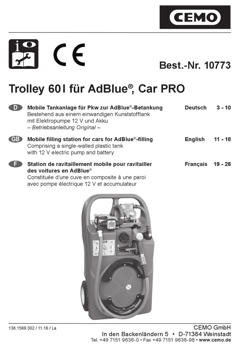
CEMO Trolley 60 l AdBlue Car PRO User manual

CEMO
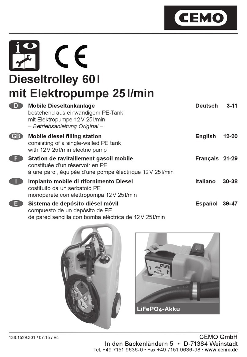
CEMO Fuel Trolley 53l User manual

CEMO
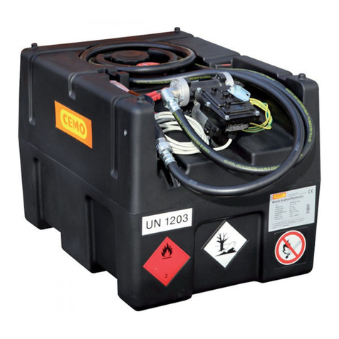
CEMO DT-Mobil Easy 430l User manual

CEMO
CEMO KS-Mobil Easy 120l User manual

CEMO
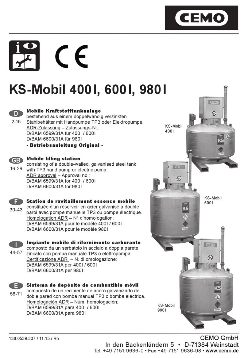
CEMO KS-Mobil 980l User manual

CEMO
CEMO Trolley 60 l AdBlue Car PRO User manual

CEMO
CEMO Trolley 60 l AdBlue Car PRO User manual

CEMO
CEMO Trolley 60 l AdBlue Car PRO User manual

CEMO
CEMO CENTRI SP30 User manual