Centsys A10 User manual

A10 Installation manual
INDUSTRIAL
SLIDING GATE
OPERATOR

Page 2
Company ProfileCompany Profile
Centurion Systems (Pty) Ltd, South Africa, has been manufacturing automatic gate systems since 1986,
and is committed to providing reliable, cost effective solutions in the field of gate and access
automation.
We offer a diverse range of products including gate motors, GSM-based products, garage door motors,
remote controls, keypads, traffic barriers, proximity access control and intercom systems.
Our products are developed by an in-house team of talented engineers that are constantly researching
new and innovative technologies to improve our existing products and expand our product range.
Our production facility in Johannesburg is ISO:9001 quality assurance certified, and all our products are
manufactured to the highest level of quality with a 100% test to specification.
Through a team of dedicated technicians and sales personnel, together with a fully fledged in-house
training facility, we are committed to providing unmatched service to our customers and support for our
products.
A worldwide network of distributors and installers ensure that our products remain The Automatic
Choice in access automation .
Further information is available on our website www.centsys.com.au
Centurion Systems (Pty) Ltd reserves the right to make changes to the products described in this document without notice and without
obligation of Centurion Systems (Pty) Ltd to notify any persons of any such revisions or changes. Additionally, Centurion Systems (Pty) Ltd
makes no representations or warranties with respect to this document.
No part of this document may be copied, stored in a retrieval system or transmitted in any form or by any means electronic, mechanical,
optical or photographic, without the express prior written consent of Centurion Systems (Pty) Ltd.

Page 3
Important Safety InstructionsImportant Safety Instructions
To ensure the safety of people, it is important that you read all the
following instructions. Incorrect installation or incorrect use of
theproductcouldcauseseriousharmtopeople.
ATTENTION
The installer, being either professional or DIY, is the last person on the site that can ensure that the
operatorissafelyinstalled,andthatthewholesystemcanbeoperatedsafely.
WARNINGS FOR THE INSTALLER
1. CAREFULLY READ AND FOLLOW ALL INSTRUCTIONS supplied with the product, or by Centurion Systems (Pty)
beforebeginningtoinstalltheproduct. Ltd.
2. This appliance is not intended for use by persons 14. Make sure that the earthing system is correctly
(including children) with reduced physical, sensory or constructed, and that all metal parts of the system are
mental capabilities, or lack of experience and knowledge, suitablyearthed.
unless they have been given supervision or instruction 15. Safety devices must be fitted to the installation to guard
concerninguseof the appliance*by a personresponsible against mechanical movement risks such as crushing,
fortheirsafety. draggingandshearing.
3. All installation, repair, and service work to this product 16. It is recommended that at least one warning indicator light
mustbedonebyasuitablyqualifiedperson. befittedtoeverysystem.
4. Donot activateyour gateopenerunless youcan seeit and 17. Always fit the warning signs visibly to the inside and
candeterminethatitsarea oftravelis clearofpeople, pets, outsideofthegate.
orotherobstructions. 18. The installer must explain and demonstrate the manual
5. NO ONE MAY CROSS THE PATH OF A MOVING GATE. operation of the gate in case of an emergency, and must
Always keep people and objects away from the gate and handtheUser/Warningsguideovertotheuser.
itsareaoftravel. 19. Explain these safety instructions to all persons authorized
6. NEVER LET CHILDREN OPERATE OR PLAY WITH THE to use this gate, and be sure that they understand the
GATE CONTROLS, and do not allow children or pets near hazardsassociatedwithautomatedgates.
thegatearea. 20. Do not leave packing materials (plastic, polystyrene, etc.)
7. Securealleasily accessedgateopenercontrols inorderto within reach of children as such materials are potential
preventunauthorizeduseofthegate. sourcesofdanger.
8. Do not in any way modify the components of the 21. Dispose of all waste products like packaging materials,
automatedsystem. wornoutbatteries,etc,accordingtolocalregulations.
9. Do not install the equipment in an explosive atmosphere: 22. Always check the obstruction detection system, and
the presence of inflammable gas or fumes is a serious safetydevicesforcorrectoperation.
dangertosafety. 23. Centurion Systems (Pty) Ltd does not accept any liability
10. Before attempting any work on the system, cut electrical caused by improper use of the product, or for use other
poweranddisconnectthebatteries. thanthatforwhichtheautomatedsystemwasintended.
11. Themainspower supplyofthe automatedsystemmust be 24. This product was designed and built strictly for the use
fittedwith an all-poleswitch with contactopening distance indicated in this documentation. Any other use, not
of 3mm or greater. Use of a 5A thermal breaker with all- expressly indicated here, could compromise the good
polecircuitbreakisrecommended. condition/operation of the product and/or be a source of
12. Make sure that an earth leakage circuit breaker with a danger.
thresholdof30mAisfittedupstreamofthesystem. 24. Everything not expressly specified in these instructions is
13. Never short circuit the battery and do not try to recharge notpermitted.
the batteries with power supply units other than that
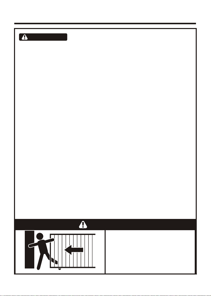
MOVING GATE CAN CAUSE
SERIOUS INJURY OR DEATH
KEEP CLEAR. GATE MAY MOVE AT
ANY TIME. DO NOT ALLOW
CHILDREN TO PLAY IN AREA OR
OPERATE GATE .
WARNING
Appliance should be product described in manual
*

These abbreviated instructions are for the experienced installer who needs a checklist to get a
standard installation up and running in the minimum of time.
Detailed installation features and functions are referred to later in this manual.
Fast TrackFast Track
Page 4
Action
Mechanical Setup
Gather required tools and equipment Page 13
Heed necessary site considerations Page 14-17
Check cabling requirements Page 18
Secure foundation plate Page 19-21
Introduce oil Page 22
Mount gearbox Page 23
Mount chain drive hardware (Optional) Page 26
Mount rack Page 24
Mount chain (Optional) Page 27
Mount origin marker Page 28
Test endstops Page 15
Step 1Step 1
Step 2Step 2
Step 3Step 3
Step 4Step 4
Step 5Step 5
Step 6
Step 6
Step 6
Step 6
Step 6 (chain)
Step 7 (chain)
Step 7Step 7
Step 8Step 8
Step 9Step 9

Get into programming mode: Page 30
Fit the SET link.
Briefly depress the reset button.
Set the gate limits: Page 30
Press and hold TEST, release after one flash of L1.
Press and hold TEST, release after one or two
flashes of STATUS. (one flash = gate opens to the RIGHT.
two flashes = gate opens to the LEFT).
Set additional features: (If required) Page 32
Exit programming mode:
Remove the SET link.
Perform installation hand over Page 48
Connect all wiring: Page 30
Step 1Step 1
Step 2Step 2
Step 3Step 3
Step 4Step 4
Step 5Step 5
Step 6Step 6
Page 5
Action
Electrical Setup
Fast TrackFast Track

General DescriptionGeneral Description
Page 6
TheA10isaheavydutyslidinggateoperatordesignedtoopenandcloseslidinggates.
In cases where chain, (as opposed to toothed rack) drive is required, an optional chain drive kit is
available.
ThekeytotheA10'soutstandingtorqueanddutycycle liesin the3-phase inductionmotor andelectronic
inverter that form the heart of the system. Single-phase 220-240VAC power is converted into variable
frequency3-phasepower,allowingelectronicallycontrolledsoftstartingandstoppingofthemotor.
An optional DC converter is available, containing back up batteries and UPS type backup circuits. This
enablestheA10tocontinueoperatingforalimitedperiodintheeventofapowerfailure.
Inordertocaterforhighdutycycleinstallations,theA10Endurancemodelisoffered.Thismodelutilizesa
continuously powered cooling fan, whilst the basic model utilizes the motor's standard shaft driven
cooling fan. The A10 heavyweight model is similar to the Endurance model with the exception of the 17
toothoutputpinion.Itissuitableforsiteswithagatemassupto2000kg
Gate travel limits are managed by an opto-electronic system, comprising a gate mounted origin marker
andaninternalrotaryencoder.Thissystemyieldspreciseandrepeatablecontrolovergateposition.
AdvancedfeaturesoftheCP201logiccontrollerinclude:-
!Automatedsetupofgateendpoints(limits).
!Failsafecollisiondetectionandautoreverse(adjustablesensitivity).
!Smoothed start/stop(rampup/down).
!Multipleoperationalmodes.
!Selectable,adjustableautoclosing.
!Pedestrian(partial)opening.
!PositiveCloseMode.
!Safetyinputforsensitiveedge/safetybeam/inductiveloop.
!Advancedlightning/surgeprotection.
!Timedcourtesylightoutput.
!Multiplepreflashingmodes.
!SPRINTgatemode(highspeedoperation).
LightningProtection
The A10 inverter and electronic controller utilizes the same proven surge protection philosophy that is
used in all CENTSYS products. While this does not guarantee that the unit will not be damaged in the
eventofalightningstrikeorpowersurge,itgreatlyreducesthelikelihoodofsuchdamageoccurring.The
earthreturn for the surge protection is providedvia the mains power supply earth.In order to ensure that
thesurgeprotectioniseffective,itisessentialthattheunitisproperlyearthed.

Page 7
Overall Dimensions
Theft Protection
Figure 1 Overall Dimensions
All dimensions shown in millimetres
384
300
340 (Theft resistant cage) 234
70
Whilecarehas been taken in the design of the A10 to preventunauthorized removal (theft) of the unit, an
optionalsteeltheftresistantcageisalsoavailableforaddedpeaceofmind.

Page 8
SPECIFICATIONS
DC CONVERTER SPECIFICATIONS
Power Supply
Maximum Absorbed Current
Motor Voltage
Output Pinion
Starting Thrust
Rated Thrust
Operating Speed @ Rated Thrust
Motor Cooling
2
Duty Cycle (continuous)
2
Duty Cycle (30 minute endurance)
Ambient Temperature Range
Anti-crushing sensing
Motor Thermal Protection
Maximum Gate length
IP Rating
Optional Battery Back-up
Shipping Mass of Unit
Maximum Gate Mass
A10 BASIC
220-240V AC+/- 10%, 50Hz - 1 Phase
6A
220-240V AC 3 Phase
20 Tooth Mod 4
(Standard speed) 40kgF
(Standard speed) 30kgF
(Standard speed) 1000kg
(Sprint speed) 30kgF
(Sprint speed) 22.5kgF
(Sprint speed) 600kg
1Adj. Up to 30m/min
16m/min
Direct Drive Fan (1400RPM)
45%
65%
O O
-20 C to +50 C
Electronic
Electronic
20m
44
Yes
15.5kg
Input Voltage 12V DC
Current Draw @ Rated Thrust 30A
Rated Output Voltage 310V DC
Battery Charger 31A
Maximum Duty Cycle 20%
Thermal Protection Electronic
Enclosure IP65 External Plastic Enclosure
Dimensions 310mm X 240mm X 110mm
Battery Size Std. 12V 7AH (External 40AH optional)
Shipping Mass
4
Open and Close Cycles
10kg (Inc 7AH Battery)
7 - 12 (7AH battery) 40 - 70 (40AH battery)
Specifications

Page 9
A10 ENDURANCE A10 HEAVY WEIGHT
220-240V AC +/- 10%, 50Hz - 1 Phase 220-240V AC +/- 10%, 50Hz - 1 Phase
6A 6A
220-240V AC 3 Phase 220-240V AC 3 Phase
20 Tooth Mod 4 17 Tooth Mod 4
47kgF
35kgF
1Adj. Up to 30m/min
16m/min 13.6m/min
High Efficiency Fan (3000 RPM) High Efficiency Fan (3000 RPM)
90% 90%
95%
95%
O O
-20 C to +50 C O O
-20 C to +50 C
Electronic Electronic
20m 17m
44 44
Yes Yes
15.7kg 15.6kg
2 000kg
(1) Refer to RATED THRUST values
O
(2) At rated thrust and 25 C maximum ambient
temperature, unit in full shade.
(3) Upgradable on request.
(4) Dependent on site / environmental conditions.
(Standard speed) 40kgF (Sprint speed) 30kgF
(Standard speed) 30kgF (Sprint speed) 22.5kgF
(Standard speed) 1000kg (Sprint speed) 600kg

Page 10
Duty Cycle Curves
Calculatingthedutycycle
Thedutycycleisthe ratio of theactualoperatingtimetothe total time (openingplus
closingpluspausetimes).Theformulaforcalculatingitisthefollowing:
where: To
Tc
Tp
Ti
opening time;
closing time;
pause time;
interval between a complete cycle and the next
=
=
=
=
% = x 100Duty cycle To + Tc
To + Tc + Tp + Ti
Figure 2 Duty Cycle Curves
A10 BASIC Duty Cycle Curves
40
50
60
70
80
90
100
20 30 40 50 60 70 80 90
Time (Minutes)
Duty Cycle(%)
HSOpen/ HSCl ose
HSOpen/ STD Close
ST D Open/ STD Close
4m500kg gate @ 20kg pull force. Air temperature=25°C. Unit in full shade.

Page 11
Figure 3 Duty Cycle Curves
A10 ENDURANCE Duty Cycle Curve
All speed combinations
70
80
90
100
20 30 40 50 60 70 80 90
Time (Minutes)
Duty Cycle (%)
4m500kg gate @ 20kg pull force. Air temperature=25°C. Unit in full shade.
Examplesofhowtoreadthedutycyclecurves:
Referring to Figure 2, an A10 Basic, opening and closing at standard (STD)speed (n),
canrunatadutycycleof65%for30minutes,adutycycleof50%for45minutes,and
adutycycleof45%foranunlimitedtime.
The same A10 Basic, opening at high speed (HS), and closing at standard (STD) speed
(6),canrunatadutycycleof78%for30minutes,adutycycleof65%for45minutes,
andadutycycleof60%foranunlimitedtime.
The same A10 Basic, opening AND closing at high speed (HS) (s), can run at a duty
cycle of 90% for 30 minutes, a duty cycle of 83% for 45 minutes, and a duty cycle of
80%foranunlimitedtime.

Theactualcomponentssuppliedmayvarydependingonthemodelpurchased.
Product IdentificationProduct Identification
Figure 4 Product Identification
Page 12
1. High Efficiency Fan* 9. 3 Phase Motor
2. Inverter Module 10. Gate Mounted Origin Marker
3. Inverter Fuse (F1 5A F/B) 11. Origin Sensor
4. Logic Controller Fuse (F2 50mA S/B) 12. Origin Marker Bracket
5. Courtesy Light Fuse (F3 3A F/B) 13. Encoder Sensor
6. Manual Release Handle 14. Lower Cover
7. Lock Cover 15. Foundation Plate
8. Logic Controller *Not fitted to BASIC model
1
2
3
4
5
6
7
8
9
12
13
14
15
10
11

Required Tools & EquipmentRequired Tools & Equipment
Masonry Bits - 6mm
20mm (For sites with rawlbolted
foundation plates)
Steel Bits 8,5mm/5,0mm/4,0mm
Spanners
17mm
13mm Screw Drivers:
3.5mm Flat
Crimping Tool
and Pin Lugs Self locking
Pliers
Pliers
Side Cutters
Hammer
G-Clamp x2
Electric
Drilling
Machine
Measuring Tape
6mm Allen Key
4mm Allen Key
Hacksaw
Welding
Machine
Pick
Spade
Level
Page 13
Figure 5 Required Tools and Equipment

Page 14
Installthegateoperatoronlyif:
1. Itwillnotposeahazardtothepublic.
2. Thereissufficientclearancetoaroadwayand/orpublicthoroughfares.
3. The installation will meet all municipal and/or local authority requirements once
completed.
4. Thegatemass,lengthandapplicationiswithintheoperatorspecifications.
5. Thegateisingoodworkingorder,meaning:
!Thatitmovesfreely.
!Doesnotmoveonitsownifleftinanyposition.
6. It can be installed to have sufficient clearance between moving parts when
openingandclosingtoreducetheriskofpersonalinjuryandentrapment.
7. Pushbuttons or key switches, when required, can be positioned so that the gate
isinlineofsightoftheoperator.
Site ConsiderationsSite Considerations
Generalconsiderationsfortheinstallation:
1. Always recommend the fitment of additional safety equipment such as safety
edges and safety beams, for additional protection against entrapment or other
mechanicalrisks.
2. Checkthatnopipesorelectricalcablesareinthewayoftheintendedinstallation.
3. Check that enough space is available for the gate operator with the gate in the
requiredopenposition.
4. Check for loose sandy soil if installing foundations, as the soil condition may
requirealargerfoundation.
5. Neverfittheoperatorontheoutsideofthegate,wherethepublichasaccesstoit.

Page 15
Endstops
Ø16mm
h
H
FIT ENDSTOPS (1) CAPABLE OF STOPPING THE GATE MOVING
AT RATED SPEED.
MAKE H≥hTO ENSURE GATE WILL NOT JUMP OVER ENDSTOP.
11
Figure 6 Gate Endstops
WARNING Due to the high speed at which the A10 operator can move a gate, it is
extremely important to install endstops capable of stopping the gate
moving at the rated speed. Refer to Specifications as detailed on Page 8
fortheoperatingspeed.

5
4
Anti-Lift Brackets
Page 16
3
2
Figure 7 Anti-Lift Brackets
- Guide-rollers must ensure that the gate is held vertically.
- Fit suitable anti-lift brackets . The gap should be <5mm to ensure
the gate cannot be lifted off the motor pinion.
- For improved safety fit additional support post to prevent gate from
falling over if guide-rollers fail.
2
2
53
4

- The Centurion Systems (Pty) Ltd warranty will be void if the pull force ,
and/or gate mass, exceeds the operator specification (see table below)
6
Starting & Running Forces
Page 17
6
Figure 8 Starting and Running Forces
Heavy Weight
47kgF
35kgF
2000kg
Basic / Endurance
40kgF @ standard speed
30kgF @ standard speed
1000kg @ standard speed
30kgF @ sprint speed
22.5kgF @ sprint speed
600kg @ sprint speed
Model
Characteristic
Starting Force
Running Force(rated)
Maximum gate mass

Page 18
Cabling RequirementsCabling Requirements
1
To dwelling
Mains
isolator
switch
2
5
1. 220-240V AC mains cable via mains 5. Infrared beams or safety edge (if
2 2
isolator switch (3 core LNE 1,5mm )† required) (3 core 0,5mm
multistranded)
2. Intercom cable (n1 + 6 core) to 2
house. 6. Intercom cable (n2+2 core 0,5mm
multistranded) to gate station.
2
3. Radio receiver cable (3 core 0,5mm
multistranded). 7. 220-240V AC mains cable for lights
2
(3 core LNE 0,5mm provided load
4. Pedestrian key switch (if required) (2 does not exceed 400W)
2
core 0,5mm multistranded).
LEGEND
n1 = number of cores required by intercom.
† Screened cable is always recommended to provide better protection against lightning - earth one end of
screening.
n2 = number of cores required by intercom.
6
3
4
7
Figure 9 Cabling Requirements

Side Clearance
Page 19
Foundation Plate Installation
Rack/Axle Clearance
5mm
Lower cover is approximately 5mm wider than chassis each side. Allow additional 20mm each
side of lower cover if theft resistant bracket is to be fitted.
Operator InstallationOperator Installation
Remember to insert mtg bolts,
before fixing foundation plate.
28mm Minimum
Use steel rack
Foundation plate
43-48mm 16mm Dia round
bar recommended
Figure 10 Rack Axle Clearance
Figure 11 Side Clearance

Foundation Plate Installation - option 1
(Bolted down to existing concrete block)
!TheLHconcreteanchor mayneedtobebrokenoffinordertoclearincoming
conduits.
!MakesuretheM10bolts 8 whichsecurethegearboxareinplace.
!Refer to the Fig. 10 to ensure correct positioning. Mark through the foundation
plateholestoindicatewheretodrillholesfortheM10rawlbolts 9.
!Useextrawashers 10 asrequired toensurethefoundationplate islevel.
!Drilltheholes,greasethebolts,andboltdowntheplatesecurely.
7
Page 20
Operator InstallationOperator Installation
Figure 12 Foundation Plate Installation - Existing Concrete Block
8
10
8
7
200mm 178mm
96mm see
above
250mm
400mm
9
Remember to
insert mtg bolts,
before fixing
foundation plate.
28mm Minimum
Use steel rack
Foundation plate
43-48mm 16mm Dia round
bar recommended
Other manuals for A10
1
Table of contents
Other Centsys Gate Opener manuals

Centsys
Centsys D5-Evo Quick start guide

Centsys
Centsys D5-Evo User manual

Centsys
Centsys Vector2 400 User manual

Centsys
Centsys D10 Turbo User manual

Centsys
Centsys D3 User manual

Centsys
Centsys D5-Evo User manual

Centsys
Centsys VECTOR2 User manual

Centsys
Centsys R3 User manual

Centsys
Centsys A10 User manual
Popular Gate Opener manuals by other brands

fadini
fadini Dardo 424 instruction manual

Dea
Dea 202 E Instructions and warnings

E.T. Systems
E.T. Systems Wingo 3524HS User instructions

Dea
Dea OLI/N Series Operating instructions and warnings

WORKMASTER
WORKMASTER GO-A8-PW Operator's guide

Nice
Nice 5024 Kit Instructions and warnings for installation and use