CE+T Power TSI NOVA User manual

Copyright © 2013. Construction electroniques & telecommunications S.A.
All rights reserved. The contents in document are subject to change without notice.
The products presented are protected by several international patents and trademarks.
Address: CE+T S.a, Rue du Charbonnage 12, B 4020 Wandre, Belgium
www.cet-power.com - info@cet-power.com
DUAL INPUT INVERTER
Commercial Power as default source
AC BACKUP IN A DC ENVIRONMENT
Leverage your existing DC infrastructure
ONE STOP SHOP
Wide output power range
HARSHEST AC INPUT CONDITIONS
Without compromising the quality of the AC output
BEYOND THE INVERTER
THE NEW GENERATION OF POWER CONVERTERS
www.cet-power.com
TSI NOVA - 230VAC
User Manual V7.3

2 – TSI Nova – User manual – v7.3
Table of content
1. CE+T Power at a glance............................................................................................................................................ 6
2. Abbreviations............................................................................................................................................................ 7
3. Warranty and Safety Conditions ................................................................................................................................ 8
3.1 Disclaimer ........................................................................................................................................................ 8
3.2 Technical care .................................................................................................................................................. 8
3.3 Installation........................................................................................................................................................ 9
3.3.1 Handling ............................................................................................................................................... 9
3.3.2 Surge and transients............................................................................................................................. 9
3.3.3 Other .................................................................................................................................................... 9
3.4 Maintenance .................................................................................................................................................... 10
3.5 Replacement and Dismantling .......................................................................................................................... 10
4. TSI TECHNOLOGY ..................................................................................................................................................... 11
4.1 On-line Mode.................................................................................................................................................... 12
4.2 Safe mode........................................................................................................................................................ 12
4.3 EPC-mode ........................................................................................................................................................ 12
4.4 Mix mode & Walk-in mode................................................................................................................................ 12
5. Building blocks ......................................................................................................................................................... 13
5.1 Inverter............................................................................................................................................................. 13
5.2 Sub-rack .......................................................................................................................................................... 13
5.3 Monitor unit T1S/T2S........................................................................................................................................ 14
6. Accessories .............................................................................................................................................................. 15
6.1 Cabinet............................................................................................................................................................. 15
6.2 Manual by-pass................................................................................................................................................ 15
6.3 AC distribution unit ........................................................................................................................................... 16
6.3.1 Distribution Rack .................................................................................................................................. 16
7. Monitoring accessories ............................................................................................................................................. 17
7.1 Can Dis shelf .................................................................................................................................................... 17
7.1.1 Display ................................................................................................................................................. 17
7.1.2 TCP/IP Agent......................................................................................................................................... 17
8. System Design.......................................................................................................................................................... 18
8.1 Pack / A la Carte............................................................................................................................................... 18
8.1.1 Pack .................................................................................................................................................... 18
8.1.2 A la Carte.............................................................................................................................................. 18
9. Installation of Nova PACK or Single shelf/shelves ...................................................................................................... 19
9.1 Mounting kit (Nova PACK or Single shelf) .......................................................................................................... 19
9.2 Electrical installation (Nova PACK or single shelf) .............................................................................................. 20
9.2.1 Prerequisites......................................................................................................................................... 20
9.2.2 Surge suppression................................................................................................................................ 21
9.2.3 Terminations......................................................................................................................................... 21
9.2.4 Grounding............................................................................................................................................. 21
9.2.5 DC input ............................................................................................................................................... 21

3 – TSI Nova – User manual – v7.3
9.2.6 AC input................................................................................................................................................ 21
9.2.7 AC output.............................................................................................................................................. 22
9.2.8 Signalling.............................................................................................................................................. 22
9.2.9 Remote ON/OFF.................................................................................................................................... 23
9.2.10 Internal Bus (TSI Bus 6 pin / TSI Bus 8 pin) ........................................................................................... 24
9.2.11 Rear cover ............................................................................................................................................ 24
10. Installation of cabinet (A la Carte)............................................................................................................................. 25
10.1 Unpacking the system ...................................................................................................................................... 25
10.2 Raising the cabinet ........................................................................................................................................... 25
10.3 Fixing the cabinet to the floor............................................................................................................................ 25
10.4 Electrical installation......................................................................................................................................... 25
10.4.1 Positioning............................................................................................................................................ 26
10.4.2 Cabling ................................................................................................................................................. 26
10.4.3 Grounding............................................................................................................................................. 27
10.4.4 AC Input (X2)......................................................................................................................................... 27
10.4.5 DC input (X1) ........................................................................................................................................ 28
10.4.6 Connection Table – AC Input (X2) ......................................................................................................... 28
10.4.7 Connection Table DC Input -48VDC (X1) ................................................................................................ 29
10.4.8 Signalling.............................................................................................................................................. 29
11. Interface .................................................................................................................................................................. 31
11.1 Inverter module ................................................................................................................................................ 31
11.2 T1S .................................................................................................................................................................. 32
11.2.1 T1S alarm............................................................................................................................................. 32
11.3 T2S .................................................................................................................................................................. 32
12. System set up.......................................................................................................................................................... 33
12.1 Communication settings ................................................................................................................................... 33
12.2 Menu access .................................................................................................................................................... 34
13. Inserting/removing/replacing modules ..................................................................................................................... 35
13.1 TSI Inverter....................................................................................................................................................... 35
13.1.1 Removal ............................................................................................................................................... 35
13.1.2 Inserting ............................................................................................................................................... 35
13.2 T1S/T2S ........................................................................................................................................................... 36
13.2.1 Removal ............................................................................................................................................... 36
13.2.2 Inserting ............................................................................................................................................... 36
13.3 Fan replacement............................................................................................................................................... 36
14. AC output distribution............................................................................................................................................... 38
14.1 DU connection installation/removal................................................................................................................... 38
14.2 Miniature Circuit breaker installation/removal................................................................................................... 38
15. Manual By-pass....................................................................................................................................................... 39
15.1 Prerequisites .................................................................................................................................................... 39
15.2 Single Phase systems....................................................................................................................................... 39
15.2.1 Manual by-pass <4.5kVA...................................................................................................................... 39
15.2.2 Manual by-pass 4.5kVA to 20 KVA ........................................................................................................ 40
15.2.3 Manual by-pass >20kVA....................................................................................................................... 40
15.3 Three Phase systems ....................................................................................................................................... 41

4 – TSI Nova – User manual – v7.3
15.3.1 Manual by-pass.................................................................................................................................... 41
16. Finishing.................................................................................................................................................................. 42
17. Commissioning ........................................................................................................................................................ 43
17.1 Check list ......................................................................................................................................................... 44
18. Trouble Shooting and Defective Situation Resolution ................................................................................................ 45
18.1 Trouble Shooting............................................................................................................................................... 45
19. Maintenance............................................................................................................................................................ 46
19.1 Access T2S with lap top.................................................................................................................................... 46
19.2 Manual check................................................................................................................................................... 46
19.3 Optional............................................................................................................................................................ 46
19.4 Manual by-pass ............................................................................................................................................... 46
20. Defective modules ................................................................................................................................................... 47
21. Appendix.................................................................................................................................................................. 48
21.1 Cabinet foot print, layout................................................................................................................................... 48
21.2 Single phase circuit diagram ............................................................................................................................ 49
21.3 Three phases circuit diagram ........................................................................................................................... 50
21.4 Mains connection, single phase........................................................................................................................ 51
21.5 Mains connection, three phases........................................................................................................................ 52

Release Note:
Version Release date
(DD/MM/YYYY)
Modified
page number Modifications
7.0 10/12/2012 - First release of the Manual.
7.1 to 7.2 18/10/2013 - Amendment and correction.
7.3 24/10/2016 - Amendment and correction.
5 – TSI Nova – User manual – v7.3

1. CE+T Power at a glance
CE+T Power designs, manufactures and markets a range of products for industrial operators with mission critical applications,
who are not satisfied with existing AC backup systems performances, and related maintenance costs.
Our product is an innovative AC backup solution that unlike most used UPS’s
Maximizes the operator’s applications uptime;
Operates with lowest OPEX;
Provides best protection to disturbances;
Optimizes footprint.
Our systems are:
Modular
Truly redundant
Highly efficient
Maintenance free
Battery friendly
CE+T power puts 60+ years expertise in power conversion together with worldwide presence to provide customized solutions and
extended service 24/7 - 365.
6 – TSI Nova – User manual – v7.3
CE+T Power at a glance

2. Abbreviations
TSI Twin Sine Innovation
EPC Enhanced Power Conversion
REG Regular
DSP Digital Signal Processor
AC Alternating current
DC Direct current
ESD Electro Static Discharge
MET Main Earth Terminal
MBP Manual By-pass
TCP/IP Transmission Control Protocol/Internet Protocol
USB Universal Serial Bus
PE Protective Earth
N Neutral
PCB Printed Circuit Board
TRS True Redundant Structure
MCB Miniature Circuit Breaker
MCCB Molded Case Circuit Breaker
CB Circuit Breaker
7 – TSI Nova – User manual – v7.3
Abbreviations

3. Warranty and Safety Conditions*
WARNING:
The electronics in the power supply system are designed for an indoor, clean environment.
When installed in a dusty and/or corrosive environment, outdoor or indoor, it is important to:
Install an appropriate filter on the enclosure door, or on the room’s air conditioning system.
Keep the enclosure door closed during operation.
Replace the filters on a regular basis.
Important Safety Instructions and Save These Instructions.
3.1 Disclaimer
The manufacturer declines all responsibilities if equipment is not installed, used or operated according to the instructions
herein by skilled technicians according to local regulations.
Warranty does not apply if the product is not installed, used and handled according to the instructions in the manuals.
3.2 Technical care
This electric equipment can only be repaired or maintained by a “qualified employee” with adequate training. Even
personnel who are in charge of simple repairs or maintenance are required to have knowledge or experience related to
electrical maintenance.
Please follow the procedures contained in this Manual, and note all the “DANGER”, “WARNING” AND “NOTICE” marks
contained in this Manual. Warning labels must not be removed.
Qualified employees are trained to recognize and avoid any dangers that might be present when working on or near
exposed electrical parts.
Qualified employees understand how to lock out and tag out machines so the machines will not accidentally be turned on
and injure employees working on them.
Qualified employees also understand safety related work practices, including those by OSHA and NFPA, as well as knowing
what personal protective equipment should be worn.
All operators are to be trained to perform the emergency shut-down procedure.
Never wear metallic objects such as rings, watches, or bracelets during installation, service and maintenance of the
product.
Insulated tools must be used at all times when working with live systems.
When handling the system/units pay attention to sharp edges.
* These instructions are valid for most CE+T Products/Systems. Some points might however not be valid for the product
described in this manual
8 – TSI Nova – User manual – v7.3
Warranty and Safety Conditions

3.3 Installation
This product is intended to be installed only in restricted access areas as defined by UL60950 and in accordance with the
National Electric Code, ANSI/NFPA 70, or equivalent agencies.
The Inverter System may contain output over current protection in the form of circuit breakers. In addition to these circuit
breakers, the user must observe the recommended UL listed upstream and downstream circuit breaker requirements as
defined in this manual.
Please use extreme caution when accessing circuits that may be at hazardous voltages or energy levels.
The modular inverter rack is a dual input power supply. The complete system shall be wired in a way that both input and
output leads can be made power free.
REG systems and EPC systems that have no AC input wired and connected can be seen as independent power sources. To
comply with local and international safety standards N (output) and PE shall be bonded. The bonded connection between
N (output) and PE must be removed once the AC input is connected.
AC and DC circuits shall be terminated with no voltage / power applied.
The safety standard IEC/EN62040-1-1 requires that, in the event of an output short circuit, the inverter must disconnect in
5 seconds maximum. The parameter can be adjusted on T2S; however, if the parameter is set at a value > 5 seconds, an
external protection must be provided so that the short circuit protection operates within 5 seconds.
Default setting is 60 seconds.
The system is designed for installation within an IP20 or IP21 environment. When installed in a dusty or humid
environment, appropriate measures (air filtering …) must be taken.
3.3.1 Handling
The cabinet shall not be lifted using lifting eyes.
Remove weight from the cabinet by unplugging the inverters. Mark inverters clearly with shelf and position for correct
rebuild. This is especially important in dual or three phase configurations.
Empty inverter positions must not be left open. Replace with module or cover.
3.3.2 Surge and transients
The mains (AC) supply of the modular inverter system shall be fitted with Lightning surge suppression and Transient voltage surge
suppression suitable for the application at hand. Manufacturer’s recommendations of installation shall be adhered to. Selecting a
device with an alarm relay for function failure is advised.
Indoor sites are considered to have a working lightning surge suppression device in service.
Indoor sites Min Class II.
Outdoor sites Min Class I + Class II or combined Class I+II. The modular inverter system/rack can reach hazardous
leakage currents. Earthing must be carried out prior to energizing the system. Earthing shall be made according to local
regulations.
3.3.3 Other
Isolation test (Hi-Pot) must not be performed without instructions from the manufacturer.
9 – TSI Nova – User manual – v7.3
Warranty and Safety Conditions
3.4 Maintenance
The modular inverter system/rack can reach hazardous leakage currents. Earthing must be carried out prior to energizing
the system. Earthing shall be made according to local regulations.
Prior to any work conducted on a system/unit make sure that AC input voltage and DC input voltage are disconnected.
Inverter modules and shelves contain capacitors for filtering and energy storage. Prior to accessing the system/modules
after power down, wait at least 5 minutes to allow capacitors to discharge.
Some components and terminals carry high voltage during operation. Contact may result in fatal injury.
3.5 Replacement and Dismantling
ESD Strap must be worn when handling PCBs and open units.
CE+T cannot be held responsible for disposal of the Inverter system and therefore the customer must segregate and
dispose of the materials which are potentially harmful to the environment, in accordance with the local regulations in force
in the country of installation.
If the equipment is dismantled, to dispose of its component products, you must comply with the local regulations in force
in the country of destination and in any case avoid causing any kind of pollution.
To download the latest documentation and software, please visit our website at www.cet-power.com.
10 – TSI Nova – User manual – v7.3
Warranty and Safety Conditions

11 – TSI Nova – User manual – v7.3
TSI TECHNOLOGY
4. TSI TECHNOLOGY *
Inverter modules carrying the TSI logo and the EPC mark are triple port converters (AC in, DC in, AC out). Sinusoidal output is
converted from Mains or/and DC.
The block diagram below gives an explicit description of the topology and operation.
BOOST
DSP
T2S
EMI
FILTER
EMI
FILTER
EMI
FILTER
User
Interface
Redundant
Commuication
Bus
L
N
L’
N’
-
+
Local Signaling
The module is built around the following sub-converters
AC to DC at input
DC to DC at input
DC to AC at output
The energy can flow either from the AC source or the DC source under the control of the local DSP controller. Thanks to internal
energy buffering, the output sine wave is constant and disturbance free regardless of the active source.
The BOOST functionality multiples the nominal current for a period of 20 ms (max) in the event of downstream failures. The
upstream breakers do not have to be oversized to prevent tripping. The overload capacity is 150% for 15 seconds.
The TSI works according to True Redundant Structure (TRS) that features decentralized and independent logic, redundant
communication bus and three internal levels of disconnection to isolate a module after internal failure.
This functionality is included in every inverter module. Running them in parallel provides a modular system with, no single point of
failure, always-conditioned output, high system efficiency and 0 ms source transfer time.
* Information and data given in this chapter is intended to serve as an overview of the TSI Technology. Detailed features and parameters for each individual
module type in the range may differ and should be referred to in the dedicated data sheet.

12 – TSI Nova – User manual – v7.3
TSI TECHNOLOGY
4.1 On-line Mode
DC is the primary source of supply whilst Mains (AC) works as the secondary source. Switching time between DC input and
AC input is 0 ms (source transfer). The power delivered by the DC source (usually a battery, but possibly any other type of DC
generator) is converted to provide regulated and transient-free power to the load. In the event of a short circuit on the load side,
the boost is automatic, timely and energized for a specific duration to trip downstream protective devices.
4.2 Safe mode
Safe mode uses DC as the primary source of supply while Mains (AC) is on standby.
Mains (AC) is normally disconnected through an internal inlet relay and is only connected when down stream clearance is required
(boost) or if DC is unavailable.
The transfer between DC and AC results in a typical transfer time of 10 ms.
Typically the safe mode is used in extremely harsh environments such as railways. Under such conditions, it provides extra
isolation against mains-borne disturbances.
4.3 EPC-mode
Mains input (AC) is the primary source whilst DC works as backup.
The TSI is designed to operate on Mains on a permanent basis and to deliver output voltage conditioned with low THD.
The output sine wave is physically independent of whether the source is AC (or) DC. If the Mains is out of tolerance or goes down,
the converter seamlessly switches to DC and the converter operates in “Back-up mode” (Changeover switching time is 0 ms).
As soon as the Mains returns to its valid range, the EPC mode is automatically resumed.
The EPC mode offers higher efficiency (up to 96% depending on the model) without compromising the purity of the output sine
wave.
Remarks: REG modules:
Inverter modules carrying the TSI logo together with the REG mark work only with DC input. Sinusoidal output is converted from
DC with the module operating as a traditional inverter. EPC mode and the boost are not available with REG modules.
4.4 Mix mode & Walk-in mode
Under some circumstances the DC and AC sources can be combined. The sequence is defined by a user selectable set of
parameters. Start, control and exit are fully automatic.
A specific example of Mix-mode is the Walk-in mode where the transfer from DC source to AC source is ramped up within a fixed
and adjustable period of time.
13 – TSI Nova – User manual – v7.3
Building blocks
5. Building blocks
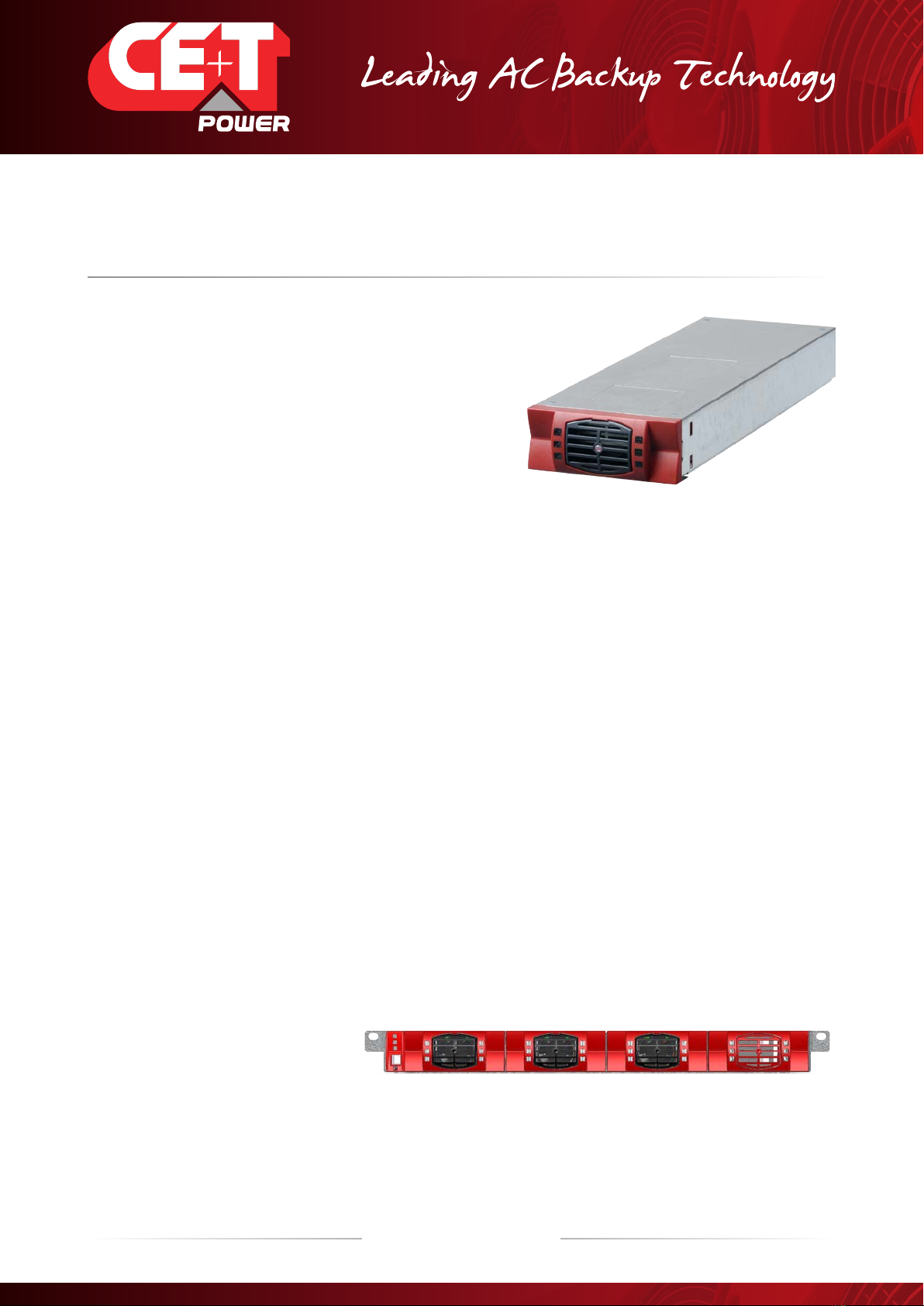
5.1 Inverter
Telecom / Datacom: -48VDC / 230VAC, 50/60Hz
The TSI NOVA is a 750 VA/525 W triple port inverter.
All versions available in EPC or REG.
The TSI inverter modules are hot swappable and hot pluggable.
The module operator interface comprises LEDs showing converter status and output power
Inverter modules run in single phase or three phase configurations.
The fan is equipped with an alarm and run time meter. The fan is field replaceable.
313 (D) x 104.5 (W) x 41.5 (H)
1.5 Kg
5.2 Sub-rack
The NOVA shelf shall be integrated in min 600 mm deep cabinets, Inch/ETSI mounting.
The NOVA shelf houses max four (4) inverter modules and one (1) monitor unit.
The extension shelf houses max four (4) inverter modules and one (1) monitor blank.
The NOVA shelf is designed with Common DC input, Common AC input and Common AC output.
Optional rear cover for IP 20 in open rack
Max 3 kVA per shelf
382 mm (D) x 19” (W) x 1U (H)
2.6 Kg empty
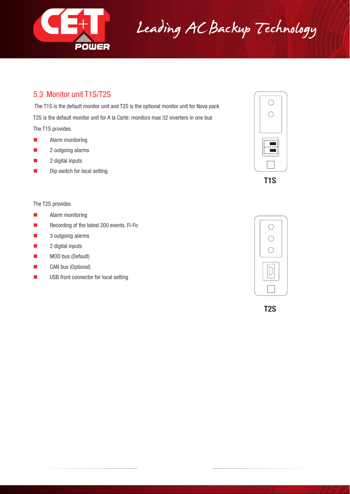
5.3 Monitor unit T1S/T2S
The T1S is the default monitor unit and T2S is the optional monitor unit for Nova pack
T2S is the default monitor unit for A la Carte; monitors max 32 inverters in one bus
The T1S provides
Alarm monitoring
2 outgoing alarms
2 digital inputs
Dip switch for local setting
The T2S provides
Alarm monitoring
Recording of the latest 200 events. Fi-Fo
3 outgoing alarms
2 digital inputs
MOD bus (Default)
CAN bus (Optional)
USB front connector for local setting
T1S
T2S
14 – TSI Nova – User manual – v7.3
Building blocks

6. Accessories
6.1 Cabinet
Powder coated (RAL 7035), 19“ welded steel sheet cabinet with 600x600 mm footprint. Cabinet designed for top cabling or
bottom cabling.
1100 mm (600x600 mm) 21U
1800 mm (600x600 mm) 37U
2110 mm (600x600 mm) 44U
The cabinet comes with a separable top cover to facilitate cabling. Tie strap support at cable entrance/exit.
Door accessory optional.
6.2 Manual by-pass
The manual by-pass operates via manually operated switches that create a by-pass from mains input to output AC distribution.
Inverter modules are by-passed and possible to remove without impacting the load. When in by-pass shelves and modules have
no AC supply, DC is still present. This is maximum 20 A and only applicable up to 4.5 KVA A la Carte system/pack.
The manual by-pass is “Make before Break”
NOTE! When the system is in by-pass the load is subjected to mains disturbances.
WARNING
IF AN ATS (automatic transfer switch) IS INSTALLED UPSTREAM,
MAKE SURE THAT IT DOES NOT ALLOW TRANSFER BETWEEN
AC SOURCES OUT OF SYNC. THE MAXIMUM ALLOWED PHASE
SHIFT IS 10°.
15 – TSI Nova – User manual – v7.3
Accessories

6.3 AC distribution unit
6.3.1 Distribution Rack
The standard AC output distribution unit is designed
with a 8X6 A breaker with Lamp indication and Voltage
test point
Max current per AC DU is 20 A, max current per output connector is 6 A, applicable only up to 4.5 KVA A la Carte system/pack.
Alarm for AC output breakers a inbuilt to each individual breaker is present (OF or SD). The alarm function is common and use one
of the digital input on the control unit.
16 – TSI Nova – User manual – v7.3
Accessories

7. Monitoring accessories
7.1 Can Dis shelf
The CanDis shelf accommodates 1-3 display units and 1 TCP/IP agent.
7.1.1 Display
Backlit 2 line dot matrix
The display shows two values simultaneously
7.1.2 TCP/IP Agent
The TCP/IP interface board is mounted on the CanDis shelf and is powered within the system.
17 – TSI Nova – User manual – v7.3
Monitoring accessories

8. System Design
8.1 Pack / A la Carte
The systems designs are divided into two topologies.
8.1.1 Pack
The PACK is a pre-assembled and configured single phase inverter system comprising 19”
inverter sub rack, inverter modules, monitor device and AC output distribution breaker.
The PACK is normally mounted in a 19” rack. A mounting kit is included in the delivery.
The PACK is only available as single phase, -48 VDC, EPC-mode.
A PACK comprises max 6 inverter modules.
8.1.2 A la Carte
The A la Carte is pre-assembled and configured as a single phase or three phase system. The system comprises cabinet, inverter
sub rack, inverter modules, manual by-pass, monitor device (T2S) and AC output distribution.
The A la Carte is available as EPC (Enhanced Power Conversion) or REG (Regular) operation.
The A la Carte (single phase) populate 1 to 24 modules, max 18 kVA
The A la Carte (three phase) populate 3 to 24 modules, max 18 kVA
Dual input (AC and DC) inverter modules (EPC)
94% efficiency during normal operation (EPC)
Always conditioned and filtered output voltage
Seamless transfer (0 ms) between primary and secondary source of supply
No single point of failure
Flexible AC output distribution
T2S MOD bus default, T2S CAN bus optional
Full modularity
Full redundancy
T1S/T2S
Blank
TSI
TSI blank
AC Output
18 – TSI Nova – User manual – v7.3
System Design

9. Installation of Nova PACK or Single shelf/shelves
Read safety instructions prior to starting any work
Do NOT attempt to use lifting eyes to erect the cabinet.
System is preferably handled without modules.
Pay attention to the module position; make sure that modules are repositioned in their original slot.
T2S is always mounted in the first shelf, left hand position.
In PACK the 4th inverter position (1st sub-rack) contains an output circuit breaker.
In three phase systems modules are configured per phase 1 (A, R), phase 2 (B, S) and phase 3 (C, T). These are not
interchangeable. Make sure that modules from one phase are not mixed with modules from another phase.
The system is designed for installation in an IP20 or IP21 environment. When installed in a dusty or humid environment,
appropriate measures (air filtering …) must be taken.
9.1 Mounting kit (Nova PACK or Single shelf)
The mounting guide rail is adjustable to fit different kind of cabinet depths.
4x Fixing brackets (ref 1)
2x Slider (ref 2)
2x Mounting brackets (ref 3)
12x Mounting screws (ref 4)
12x Cage nuts (ref 5)
Assemble the sliders and adjust the length to suit the
mounting depth
Fix cage nuts (5) iin the cabinet front and left and the
right side rear frame
Fix the left and right cabinet slider with the supplied
screws (4)
2
1
1
4
3
5
4
5
19 – TSI Nova – User manual – v7.3
Installation of Nova PACK or Single shelf/shelves

Fix cage nuts (4) in the mounting frame
Assemble the mounting bracket (3) in a suitable
position.
Slide the shelf into position and fix it with the
supplied screws (5)
Finished
5
3
9.2 Electrical installation (Nova PACK or single shelf)
9.2.1 Prerequisites
The sub – rack has markings for all terminations.
All cables shall be rated at min 90 deg C.
Electrical terminations shall be tightened to 3 Nm
All connection screws are M4 x 12 mm
DC Input-Common (per shelf); observe polarity.
AC Input / AC output – Common (per shelf); respect phases.
Wire all positions in the sub-rack for future expansion
Input AC / Output AC / Input DC / Signal cables shall be separated.
Cable crossings shall be done at 90 degree angles.
20 – TSI Nova – User manual – v7.3
Installation of Nova PACK or Single shelf/shelves
Table of contents
Other CE+T Power Inverter manuals

CE+T Power
CE+T Power TSI Y-ONE Series User manual

CE+T Power
CE+T Power TSI VEDA User manual

CE+T Power
CE+T Power BRAVO ST-120 VAC-UL User manual

CE+T Power
CE+T Power TSI Bravo User manual

CE+T Power
CE+T Power BRAVO 25 User manual

CE+T Power
CE+T Power BRAVO 10 - 48/120 User manual

CE+T Power
CE+T Power e-one 10 - 48/230 User manual

CE+T Power
CE+T Power TSI MEDIA User manual

CE+T Power
CE+T Power RBS Series User manual

CE+T Power
CE+T Power Bravo 10 - 48/230 User manual


