Kramer 840Hxl User manual

KRAMER ELECTRONICS LTD.
USER MANUAL
MODEL:
840Hxl
Pattern Generator
P/N: 2900-300032 Rev 5


840Hxl – Contents
i
Contents
1Introduction 1
2Getting Started 2
2.1 Achieving the Best Performance 2
2.2 Safety Instructions 2
2.3 Recycling Kramer Products 3
3Overview 4
4Defining the 840Hxl Pattern Generator 5
5Connecting the 840Hxl 7
5.1 Connecting to a PC 8
6Operating the 840Hxl Pattern Generator 9
6.1 Operating the 840Hxl Using the Front Panel Buttons 11
6.2 Operating the 840Hxl Using the Control Application 12
7Technical Specifications 21
8Serial Protocol 22
8.1 Command Format 22
8.2 Device Response 22
8.3 Commands 23
Figures
Figure 1: 840Hxl Pattern Generator Front Panel 5
Figure 2: 840Hxl Pattern Generator Rear Panel 6
Figure 3: Connecting the 840Hxl Pattern Generator 7
Figure 4: Found New Hardware Wizard Window 13
Figure 5: File Location Selection Window 13
Figure 6: Insert Disk Window 14
Figure 7: Connection Method Window 15
Figure 8: Connection Error Message 16
Figure 9: Controller Software Main Window 16
Figure 10: Menu Bar 17
Figure 11: About 18
Figure 12: User Defined Resolution Window 18
Figure 13: User Defined Resolution Advanced Window 19
Figure 14: User Defined Resolution Advanced Window–Detailed Timing Descriptor Tab 20

840Hxl - Introduction
1
1
1 Introduction
Welcome to Kramer Electronics! Since 1981, Kramer Electronics has been
providing a world of unique, creative, and affordable solutions to the vast range of
problems that confront the video, audio, presentation, and broadcasting
professional on a daily basis. In recent years, we have redesigned and upgraded
most of our line, making the best even better!
Our 1,000-plus different models now appear in 11 groups that are clearly defined
by function: GROUP 1: Distribution Amplifiers; GROUP 2: Switchers and Routers;
GROUP 3: Control Systems; GROUP 4: Format/Standards Converters; GROUP
5: Range Extenders and Repeaters; GROUP 6: Specialty AV Products; GROUP
7: Scan Converters and Scalers; GROUP 8: Cables and Connectors; GROUP 9:
Room Connectivity; GROUP 10: Accessories and Rack Adapters and GROUP 11:
Sierra Products.
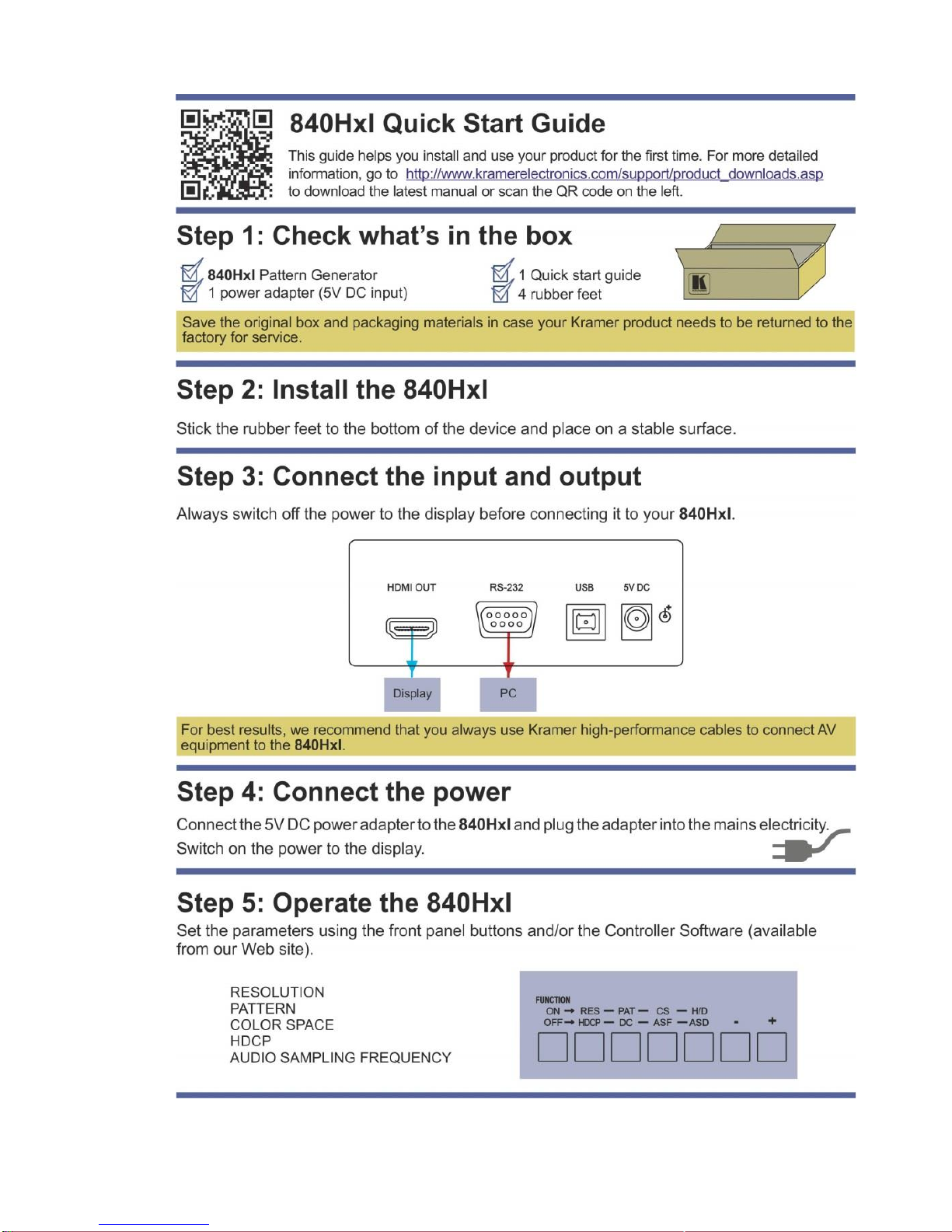
Congratulations on purchasing your Kramer MultiTOOLS®840Hxl Pattern
Generator, which is ideal for the following typical applications:
As a diagnostic tool in AV setups
Testing and adjusting flat panel LCD displays, projectors, plasmas and
HDMI cables

2
840Hxl - Getting Started
2 Getting Started
We recommend that you:
Unpack the equipment carefully and save the original box and packaging
materials for possible future shipment
Review the contents of this user manual
Go to http://www.kramerelectronics.com/support/product_downloads.asp
to check for up-to-date user manuals, application programs, and to
check if firmware upgrades are available (where appropriate).
2.1 Achieving the Best Performance
To achieve the best performance:
Use only good quality connection cables (we recommend Kramer high-
performance, high-resolution cables) to avoid interference, deterioration in
signal quality due to poor matching, and elevated noise levels (often
associated with low quality cables)
Do not secure the cables in tight bundles or roll the slack into tight coils
Avoid interference from neighboring electrical appliances that may adversely
influence signal quality
Position your Kramer 840Hxl away from moisture, excessive sunlight and
dust
This equipment is to be used only inside a building. It may only be
connected to other equipment that is installed inside a building.
2.2 Safety Instructions
Caution:
There are no operator serviceable parts inside the unit
Warning:
Use only the Kramer Electronics input power wall
adapter that is provided with the unit
Warning:
Disconnect the power and unplug the unit from the wall
before installing
i
!
!

840Hxl - Getting Started
3
3
2.3 Recycling Kramer Products
The Waste Electrical and Electronic Equipment (WEEE) Directive 2002/96/EC
aims to reduce the amount of WEEE sent for disposal to landfill or incineration by
requiring it to be collected and recycled. To comply with the WEEE Directive,
Kramer Electronics has made arrangements with the European Advanced
Recycling Network (EARN) and will cover any costs of treatment, recycling and
recovery of waste Kramer Electronics branded equipment on arrival at the EARN
facility. For details of Kramer’s recycling arrangements in your particular country
go to our recycling pages at http://www.kramerelectronics.com/support/recycling/.

4
840Hxl - Overview
3 Overview
The 840Hxl is a high performance HDMI video test pattern generator. It can
generate 32 preset patterns (including several unique patterns incorporating
motion) at 42 popular, predefined computer and HD video resolutions.
In particular, the MultiTOOLS®840Hxl features:
An HDMI output
Five dual-function and two single-function control buttons
A two-digit 7 segment display
An onboard EPROM that saves the last settings

840Hxl - Defining the 840Hxl Pattern Generator
5
5
4 Defining the 840Hxl Pattern Generator
Figure 1 defines the front panel of the 840Hxl.
Figure 1: 840Hxl Pattern Generator Front Panel
#
Feature
Function
1
FUNCTION
Buttons
ON/OFF
Press to toggle on and off. Button LED lights when on.
When on, the top row of functions are enabled (RES,
PAT, CS and H/D). When off, the bottom row of
functions (HDCP, DC, ASF and ASD) are enabled (see
Section 6.1)
2
RES/HDCP
Press to select either the Resolution or HDCP functions
3
PAT/DC
Press to select either the Pattern or Color Depth
functions
4
CS/ASF
Press to select either the Color Space or Audio Sample
Frequency functions
5
H/D / ASD
Press to select either the HDCP/DVI or Audio Sample
Depth functions
6
2-digit 7-segment Display
Indicates the current setting. The display flashes if there
is a problem communicating with the display, for
example, if the display does not support HDCP or does
not support the selected resolution
7
ON LED
Lights red when the device receives power
8
–Button
Press to step down through the list of available values
9
+Button
Press to step up through the list of available values

6
840Hxl - Defining the 840Hxl Pattern Generator
Figure 2 defines the rear panel of the 840Hxl.
Figure 2: 840Hxl Pattern Generator Rear Panel
#
Feature
Function
10
HDMI OUT Connector
Connect to the HDMI acceptor
11
RS-232 9-pin D-sub
Connector
Connect to the serial port on a PC for remote control
(see Section 5.1.1)
12
USB Connector
Connect to the USB port on a PC for remote control
13
5V DC Connector
Connect to the power adapter

840Hxl - Connecting the 840Hxl
7
7
5 Connecting the 840Hxl
Always switch off the power to any device before connecting it to your
840Hxl. After connecting your 840Hxl, connect its power and then
switch on the power to the device.
To connect the 840Hxl as illustrated in the example in Figure 3:
1. Connect the HDMI OUT connector to an HDMI acceptor (for example, a flat
panel LCD display).
2. Optional—connect a PC to control the 840Hxl via the RS-232 or USB ports.
3. Connect the power adapter to the 5V DC socket and to the mains electricity
(not shown in Figure 3).
Note: The device must be connected to the 5V supply or it will not function
correctly. If connected to a PC via the USB the device might appear to work
but it will not function correctly.
Figure 3: Connecting the 840Hxl Pattern Generator
!

8
840Hxl - Connecting the 840Hxl
5.1 Connecting to a PC
You can connect a PC either using the RS-232 port or the USB port.
5.1.1 Connecting a PC via the RS-232 Serial Port
You can connect to the 840Hxl via an RS-232 connection using, for example, a
PC. Note that a null-modem adapter/connection is not required.
To connect to the product via RS-232:
Connect the RS-232 9-pin D-sub rear panel port on the product unit via a
9-wire straight cable (only pin 2 to pin 2, pin 3 to pin 3, and pin 5 to pin 5
need to be connected) to the RS-232 9-pin D-sub port on your PC
5.1.2 Connecting a PC via the USB Port
To connect the 840Hxl via a USB port:
1. Using a USB cable, connect the 840Hxl to a USB port on the PC.
2. Install the USB driver as described in Section 6.2.1.

840Hxl - Operating the 840Hxl Pattern Generator
9
9
6 Operating the 840Hxl Pattern Generator
The 840Hxl can be operated either using the front panel buttons (see Section 6.1)
or using the 840Hxl Control Application (see Section 6.2).
The 840Hxl Control Application is available as a free download from
http://www.kramerelectronics.com).
You can choose from 24 resolutions (see Figure 9).
Common resolutions 1 through 16 are predefined. Resolution 24 is Output Native
Resolution as shown in the table below.
Common Resolutions
#
Resolution Name
Resolution
1
VGA
640 x 480 @60Hz
2
720 x 480 @60Hz
3
SVGA
800 x 600 @60Hz
4
XGA
1024 x 768 @60Hz
5
1260 x 720 @60Hz
6
1360 x 768 @60Hz
7
1440 x 900 @60Hz
8
SXGA+
1400 x 1050 @60Hz
9
SXGA
1260 x 1024 @60Hz
10
WSXGA+
1680 x 1050 @60Hz
11
SXGA
1280 x 1024 @75Hz
12
HD 1080
1920 x 1080 @60Hz
13
WUXGA
1920 x 1200 @60Hz
14
UXGA
1600 x 1200 @60Hz
15
720 x 480i @60Hz
16
HD 1080
1920 x 1080i @60Hz
24
Output Native
Resolution
User-defined resolutions 17 (Label 1) through 23 (Label 7) can be selected from
the resolutions in the following table.

10
840Hxl - Operating the 840Hxl Pattern Generator
User Defined Resolutions
Resolution
Resolution
720 x 480 @120Hz
2880 x 480 @60Hz
720 x 480 @240Hz
2880 x 480i @60Hz
720 x 576 @50Hz
2880 x 576 @50Hz
720 x 576 @100Hz
2880 x 576i @50Hz
720 x 576 @200Hz
1920 x 1080 @25Hz
1440 x 576 @50Hz
1920 x 1080 @30Hz
1440 x 576i @50Hz
1920 x 1080 @50Hz
1280 x 720 @50Hz
1920 x 1080i @50Hz
1280 x 720 @60Hz
1920 x 1080 @60Hz
1280 x 720 @100Hz
1920 x 1080i @60Hz
1280 x 720 @120Hz
1920 x 1080i @100Hz
1440 x 288 @50Hz
1920 x 1080i @120Hz
1440 x 480 @60Hz
2K 2048 x 1080 @50Hz
2880 x 240 @60Hz
2K 2048 x 1080 @60Hz
2880 x 288 @50Hz
The following patterns are supported.
#
Pattern
#
Pattern
1
100% Color bar
17
Square
2
75% Color bar
18
White dot
3
Gray 8
19
Alternate pixels
4
Red screen
20
White HScroll
5
Green screen
21
White VScroll
6
Blue screen
22
Multiburst
7
Yellow screen
23
Horizontal split
8
Cyan screen
24
Vertical split
9
Magenta screen
25
Red ramp
10
Gray 16
26
Green ramp
11
White screen
27
Blue ramp
12
RGB ramp
28
Bounce
13
Crosshatch black
29
Window
14
Crosshatch red
30
White border
15
Crosshatch green
31
Target circle
16
Crosshatch blue
32
Moving ball

840Hxl - Operating the 840Hxl Pattern Generator
11
11
The output options in the following table are supported.
Parameter
Front Panel
Values
Signal Mode
H/D
HDMI (video, audio and data
packet), DVI (video only), Auto
HDCP
HDCP
On, Off
Color Space
CS
RGB, YUV 444, YUV 422, Auto
Color Depth
DC
24 bit, 30 bit, 36 bit, Auto
Audio Sample Rate
ASF
44kHz, 48kHz, 88kHz, 96kHz,
176kHz, 192kHz, Auto
Audio Sample Depth
ASD
16 bit, 20 bit, 24 bit, Auto
6.1 Operating the 840Hxl Using the Front Panel Buttons
To activate the top row of functions (RES, PAT, CS and H/D):
Press the Function ON/OFF button (the button LED lights)
To activate the bottom row of functions (HDCP, DC, ASF and ASD):
Press the Function ON/OFF button again (the button LED no longer lights).
To select a function and modify the value, for example, to select a specific
pattern:
1. Press the Function button.
The button lights to indicate the top row of functions (ON) is active.
2. Press the PAT/DC button.
The button lights to indicate that the Pattern function is active.
3. Press the +or –button to cycle through the list of available patterns until the
required pattern is displayed on the 7-segment display.
Note: The display flashes if there is a problem communicating with the display, for
example, if the display does not support HDCP or does not support the selected
resolution.

12
840Hxl - Operating the 840Hxl Pattern Generator
6.2 Operating the 840Hxl Using the Control Application
The 840Hxl Control Application is a PC-based program which lets you program
and control the device.
To use the 840Hxl Control Application you must download and install the USB
driver and the 840Hxl Control Application.
Note: The USB driver is not supported by Windows 64 bit systems.
6.2.1 Downloading and Installing the USB Driver and Control
Application
To install the USB driver and Control Application:
1. Navigate to the Kramer Electronics Web site
(http://www.kramerelectronics.com) and search for the product 840Hxl.
2. Click on the Downloads tab.
3. Download the 840Hxl Windows USB Driver.
4. Download the 840Hxl Control Application to a designated folder on your
computer.
5. Extract the compressed USB driver file to your designated folder.
Two files are extracted, a .inf and a .sys file.
6. Connect the USB cable between your computer and the 840Hxl.
7. Connect the power supply to the 840Hxl.
8. After a few seconds the Found New Hardware message appears as shown
in Figure 4.

840Hxl - Operating the 840Hxl Pattern Generator
13
13
Figure 4: Found New Hardware Wizard Window
9. Click on the No, not this time option button.
10. Click Next.
11. Select Install from a list or specific location (Advanced) as shown in
Figure 5.
Figure 5: File Location Selection Window

14
840Hxl - Operating the 840Hxl Pattern Generator
12. Click Next.
13. Select Search for the best driver in these locations.
14. Check Include this location in the search. Browse to your previously
designated folder.
15. Click Next.
16. Select the file atm6124.inf
17. The warning This driver is not digitally signed! appears.
18. Click Next.
19. Ignore the warning. Click Continue Anyway.
20. In the Insert disk window, click OK as shown in Figure 6.
Figure 6: Insert Disk Window
21. Select the file atm6124.sys and click Open.
The driver installs and a success message is displayed. The USB driver has
been successfully installed and you can install the 840Hxl Control
Application.
22. Navigate to the designated folder to which you downloaded the Control
Application.
23. Double-click the file setup.exe from this folder or from the distribution media
included with the 840Hxl.
The Control Application has been successfully installed.

840Hxl - Operating the 840Hxl Pattern Generator
15
15
6.2.2 Connecting to the Device
To connect to the device:
1. Run the Control Application by clicking Start > Programs > Kramer
Electronics > 840Hxl.
2. Click the Connect button.
The Connection Method window is displayed as shown in Figure 7.
Figure 7: Connection Method Window
3. Select the required connection method (via a serial or USB connection) by
clicking the relevant radio button.
4. For a serial connection, select the required Com port from the drop-down
list.
5. For a USB connection, select the required USB device from the drop-down
list.
To view an up-to-date list of available USB ports, press the Refresh Ports
button.
Note: If the drop-down list shows No USB Devices, then either you have not
installed the USB driver (see Section 5.1.2) or the installation was not successful.
6. Click Connect.
If the connection is not successful, a Timeout error message appears as
shown in Figure 8. If the connection is successful, the main window shown
in Figure 9 appears.

16
840Hxl - Operating the 840Hxl Pattern Generator
Figure 8: Connection Error Message
6.2.3 Controller Software Main Window
The Controller Software Main Window is shown in Figure 9.
Figure 9: Controller Software Main Window

840Hxl - Operating the 840Hxl Pattern Generator
17
17
#
Feature
Function
1
CONNECT Button
Press to connect to a device (see Section 6.2.2)
2
COMMON Resolutions Buttons
Press to select a pre-configured output resolution
3
USER DEFINED Resolutions Buttons
Press to select a user-defined output resolution
4
User Defined Resolution Edit Buttons
Press to edit the relevant user defined output resolution
5
Patterns Buttons
Press to select an output pattern
6
Output Settings Buttons
Press to modify the output settings:
Signal Mode—HDMI, DVI, Auto
HDCP—HDCP, No HDCP
Color Space—RGB, YUV 444, YUV 422, Auto
Color Depth—24 bit, 30 bit, 36 bit, Auto
Audio Sample Rate—44kHz, 48kHz, 88kHz, 96kHz,
176kHz, 192kHz, Auto
Audio Sample Depth—16 bit, 20 bit, 24 bit, Auto
7
Status of Connected Display
Information on the currently connected display
8
Status of Output
Information on the currently selected output settings
9
EDID Info
Click on Get EDID Info from the menu bar to display
EDID information from the connected display. If there is
no display connected, random data is displayed
6.2.4 The Menu Bar
Figure 10: Menu Bar
There are four functions available from the menu bar:
Device Reset—Resets the device to factory default settings
Get EDID Info—Reads EDID data from an attached display device
About—Displays the current software version number, (see Figure 11)
Check for updates—Checks that the current software version is the latest
available
Other manuals for 840Hxl
1
Table of contents
Other Kramer Inverter manuals

Kramer
Kramer SG-6005 User manual

Kramer
Kramer 860 User manual

Kramer
Kramer TOOLS 810B User manual

Kramer
Kramer MultiTOOLS 850 User manual

Kramer
Kramer FC-46xl User manual

Kramer
Kramer SG-6005XL User manual

Kramer
Kramer DigiTOOLS 840 User manual

Kramer
Kramer 811 User manual

Kramer
Kramer DigiTOOLS 820 User manual

Kramer
Kramer 841 User manual