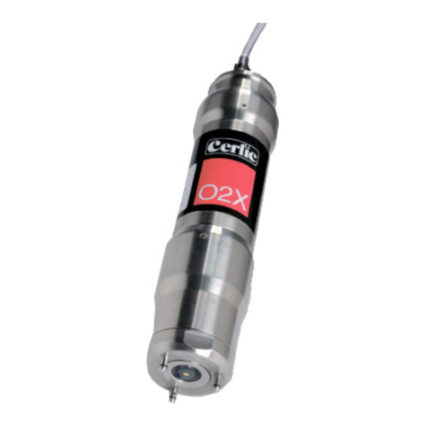
Cerlic CBX User manual

2011-11-08 C81B5EN12
CBX
Cerlic CBX
Sludge Blanket Monitor

fghj
2
CBX
Index
INDEX....................................................................................................................................................................2
GENERAL INFORMATION ................................................................................................................................................. 4
SECURITY INFORMATION................................................................................................................................................. 4
DESCRIPTION OF THE FUNCTION.................................................................................................................................... 4
WORKING PRINCIPLE ....................................................................................................................................................... 4
SENSOR BODY .................................................................................................................................................................... 4
INSTALLATION..................................................................................................................................................5
Unpacking............................................................................................................................................................................ 5
Damages............................................................................................................................................................................... 5
Packing.................................................................................................................................................................................. 5
Content.................................................................................................................................................................................. 5
Accessories........................................................................................................................................................................... 5
STARTING UP.....................................................................................................................................................6
Mechanical installation................................................................................................................................................. 6
Water connections........................................................................................................................................................... 6
Electrical connection...................................................................................................................................................... 6
Sludge rake guard limit switch, Trigger................................................................................................................ 6
USER INTERFACE .............................................................................................................................................................. 7
Configurations................................................................................................................................................................... 7
LED INDICATION .............................................................................................................................................................. 7
OPERATION........................................................................................................................................................8
CBX MODE......................................................................................................................................................................... 8
Rake interval ...................................................................................................................................................................... 8
EMERGENCY RETRACTION OF THE CABLE..................................................................................................................... 8
CONFIGURATION TERMS...............................................................................................................................9
Home position, A............................................................................................................................................................... 9
Blind zone, B ....................................................................................................................................................................... 9
Max depth, C ....................................................................................................................................................................... 9
Sludge level, D.................................................................................................................................................................... 9
Measured range, E ........................................................................................................................................................... 9
Raker, F................................................................................................................................................................................. 9
Fluff, G.................................................................................................................................................................................... 9
BB1/BB2 MENU FOR CBX...........................................................................................................................................10
Settings................................................................................................................................................................................10
CBX Setup...........................................................................................................................................................................11
Calibration.........................................................................................................................................................................11
Cleaning..............................................................................................................................................................................12
Scale / Alarm....................................................................................................................................................................12
System..................................................................................................................................................................................12
Timer....................................................................................................................................................................................13
INFORMATION DISPLAY .............................................................................................................................13
PROFILE............................................................................................................................................................ 14
CALIBRATION ..................................................................................................................................................................16
Calibration of sensor.....................................................................................................................................................16
DEITAILED INFORMATION OF CBX.........................................................................................................17
Main control board........................................................................................................................................................17
PICKUP BOARD ................................................................................................................................................................17
Axle board..........................................................................................................................................................................18
Sensor...................................................................................................................................................................................18
Cable drum assembly....................................................................................................................................................19

fghj
3
CBX
Heater & fan......................................................................................................................................................................20
Flushing tube & valve ...................................................................................................................................................20
Connection terminal .....................................................................................................................................................20
APPENDIX 6 , OPTIONAL 4-20MA OUTPUT MODULE FOR BB1/BB2 ..........................................21
INTRODUCTION ...............................................................................................................................................................21
MODULE OVERVIEW.......................................................................................................................................................21
WIRE CONNECTIONS ......................................................................................................................................................23
GETTING STARTED WITH THE 4-20 MAMODULE.....................................................................................................23
TECHNICAL SPECIFICATION FOR 4-20MAMODULE..................................................................................................23
MAINTENANCE ...............................................................................................................................................24
MANUAL OPERATION OF CBX................................................................................................................... 24
Maintenance schedule..................................................................................................................................................24
Cable and sensor.............................................................................................................................................................24
TROUBLESHOOTING .......................................................................................................................................................25
ALARM..............................................................................................................................................................................25
APPENDIX 1, MOUNTING OF CBX SUPPORT STAND.......................................................................... 26
APPENDIX 2, MOUNTING OF FLUSH PIPE ............................................................................................. 27
APPENDIX 3, WIRING DIAGRAM......................................................................................................... 28
APPENDIX 4, SAFETY INSTRUCTIONS.................................................................................................... 29
CONTACT INFORMATION ...........................................................................................................................30
WARRANTY .....................................................................................................................................................30
SPECIFICATION, CBX .................................................................................................................................... 31
DIMENSIONS IN MM (“)............................................................................................................................32
APPENDIX 7, SERVICE FORM................................................................................................................33
APPEMNDIX 8, SETUP FORM .................................................................................................................... 34

fghj
4
CBX
General information
It is of great importance to read all parts of this manual prior to startup of the
instrument. If the Blanket Monitor is not used and handled according to this manual,
then the life and functionality may be jeopardized, and all warranties will be voided.
Security information
This instrument should be used by qualified and authorized personnel only.
It is mandatory to follow all security and other routines that apply at site when
using the CBX.
Within EU it is prohibited to dispose of electric and electronic waste in regular
waste as these may contain harmful substances. All electric and electronic
waste must be sorted and left for recycling. Such products are labeled with an
X-marked waste bin. It is important that everyone cooperate in order to secure
a high level when it comes to recycling and help to save our environment. If such waste
is handled and recycled according to regulation (EC Directive 2002/96/EC) the
environment as well as people’s health may be jeopardized
Description of the function
CBX is an optical suspended solids meter designed to measure sludge and fluff blanket
depth in clarifiers, thickeners, etc. in water and wastewater plants, as well in other
facilities. It is possible to display measured values as text or as a graphic image of the
sludge profile.
Working principle
The sensor is sent down into the clarifier/thickener and measures the suspended solids
as it descends and sends the data via a communication cable to the BB2 control box. By
submersing the sensor into the liquid you are able to obtain reliable suspended solids
readings versus depth and avoid problems from foam and fluff layers in the
clarifier/thickener.
Sensor body
The sensor body contains optics and electronics that should not be exposed to
mechanical abuse or high temperatures. If the sensor body has mechanical damages,
water may penetrate into the sensor and destroy the electronics and optics. Please see
section Maintenance for more information.

fghj
5
CBX
Installation
It is important that installation, maintenance and configuration only are done by
authorized personnel to avoid damages on the product. .
Unpacking
The unit has been tested and approved before delivery from factory. Please check to
confirm that no visible damages occurred during shipment. Make sure that all
equipment inside the cabinet is secure and that the sensor and cable can move freely.
Damages
If damages occurred during shipment, immediately contact your shipper as well as your
Cerlic representative within 2 days of receipt. The shipment may be returned only after
contact has been made with Cerlic.
Packing
The original packing is designed to protect the equipment and should be used for
storage or if the goods must be returned. If other packing material is used Cerlic is not
responsible for damages during transport.
Content
Please check that the content corresponds to your order and packing list.
Options
P/N
SS Handrail Mounting Bracket 10305893
BB2 Control Box 11905426
BB1 Control Box 11905885
Mounting plate for BB1/2 10305532
M12 Cable 1.5m (5’) 20805752
M12 Cable 10m (33’) 20805510
M12 Cable 30m (100’) 20850727
Sensor with 33’ cable 11305888
Flushing Valve 115V 11705516B
Motor 115V 21750924
Fan 115V 21750926
Door key 20305403
Accessories
Cerlic Sensor Cleaning Fluid (CSC) 10905944
CBX Jacket (for cold weather) 11205969

fghj
6
CBX
Starting up
Connect the CBX to the BB1/BB2 and connect 110/1/60 power to both units. BB1/BB2
must have program version 3.1 or higher so it will automatically detect and connect to
the CBX.
Mechanical installation
Mechanical mounting is described in appendix 1 “Mounting of stand”. When CBX is
installed outdoors there is a risk of flush lines freezing at sub zero temperatures. This
will not damage the instrument but the automatic cleaning function will stop working. It
is also recommended to use a CBX Jacket (P/N 11205969) when there is a risk of
temperatures below 23ºF (-5ºC).
Water connections
On the bottom right hand side of the cabinet there is a ¼” npt male connection for
flexible flush hose. A description of the connection can be found in appendix 3
“Mounting of hose”. Outdoor installations must protect water pipe or hose from freezing
conditions or the water must be disconnected and emptied to avoid the hose or valve
from freezing. Under all circumstances flushing should be avoided when the outdoor
temperature is below 0 ºC (32ºF).
Electrical connection
In the bottom lower left corner of the cabinet there are the four (4) ½” npt female
electrical connections. Any wires required to go outside the cabinet can be found here.
Electrical connections must be installed by authorized personnel only. The connections
are terminated in the junction box inside the cabinet on the left side. Description is given
in appendix 3 “Electrical connections”.
Sludge rake guard limit switch, Trigger
All sampling modes are dependent of the connection of a rake guard limit switch which
is a N/O (normally open) contact. The digital input for the limit switch can be used in
several different ways for control of the CBX
NOTE! A limit switch must be used in all applications where a rake or other
moving equipment may come in contact with the sensor or cable. Cerlic Controls
AB does not assume any responsibility for damages caused by the absence or
malfunction of the rake guard limit switch.

fghj
7
CBX
User interface
The BB1/BB2 will show the CBX as a standard “X” sensor on the display and it will show
both sludge and fluff level in text on the display.
Configurations
The figure below shows the different terms used for distances that are involved in the
configuring of the CBX.
To set the basic parameters like, Max depth, Blind zone and scale do the following.
Lower the sensor head to 1’ (0.3m) below the liquid surface (see calibration section for
instructions), note the distance on the BB1/BB2. This is the length of cable to the blind
zone (B) . Continue to feed the sensor down until the sensor is just touching the bottom.
You can see this by watching the cable, when the sensor is all the way down the cable
will go slack. Feed sensor back up until you have about 2” (5 cm) of clearance between
the bottom of clarifier and sensor. Note the distance on the BB1/BB2, this is the Max
Depth (C). Exit the Manual UP/DOWN mode and scroll down to “CBX setup” and enter
the “blind zone (B)” “Max depth (C)” and “Measuring scale (E)” do not forget to set Rake
height (F) if you have a botton rake or if you want to compensate for a slope. Calculate
Measuring range by subtracting Blind zone from Max depth (C-B=E). Measuring range is
the max depth for sludge and fluff that correspond to 20mA on channel 1 (blanket) and 2
(Fluff).
LED indication
Red
Yellow
Green
Status
CBX Start Up, Light Test
Standby, waiting for next sample cycle
Configuration or Setup Mode
Sampling
Configuration or Setup error, check parameters
Mechanical or Electrical Problem
Cold Temp, less then 36ºF inside the unit.
Shut down the CBX to alleviate cold weather damage
Fig 1

fghj
8
CBX
Operation
All configurations are done via BB1/BB2 that is connected to the CBX. All settings shall
be done and saved (done by exiting the menu) before a new sampling is preformed.
Depth and concentration is shown on the BB1/BB2 on-line during a sampling cycle.
CBX Mode
There is two different modes the CBX can be set to, Setup and Trig.
Trig is the normal working mode. In this mode the CBX will take a sample on every
external trig from the rake limit switch.
Setup, the CBX must be set to this mode before changing calibration parameters or
using “MANUAL UP/DOWN” button.
Rake interval
The rake limit switch starts a measuring cycle. When the rake is passing the rake limit
switch the CBX will execute a sampling cycle. It is possible to configure the number of
pulses from the rake switch that is needs for a measuring cycle to start. This parameter
is called “trig int”. It can be used for delaying the time between the samples, normally
you will take a sample every 30 - 45 minute.
Emergency retraction of the cable
If the CBX for some reason does not retract the cable, then it is possible to do manually.
But always try to switch off the main power to the CBX for 10 seconds and then back on
line again. The CBX will always start with retracting the cable to “home position” after a
power loss. If the cable still does not retract use the emergency motor control switch
that is located on the box for the terminal block inside the CBX. The switch can be
located on top of the terminal box or under the lid. As a safety feature, you must press
and hold the door switch in during manual operation.
NOTE!
As a safety you must press and hold the door switch in during manual operation.

fghj
9
CBX
Configuration terms
Home position, A
The sensor will always return to this position.
Blind zone, B
Sludge or foam detected in this zone during lowering of the sensor is not registered.
Unwanted interference is prevented by setting this zone to be 1’ (0.3m) below the
normal liquid surface. Sensor does not start to measure until it reaches this distance.
Max depth, C
This is the maximum distance from the home position. The sensor will stop at this depth
if no sludge is detected. The sensor might stop and return at a shorter distance if a rake
guard offset is entered (F).
Sludge level, D
The sludge level distance from bottom found when the preset sludge concentration is
reached.
Measured range, E
The output signal will vary from 4-20 mA within this range.
Raker, F
This denotes the safe height from the bottom (Max depth) to a point where the sensor
always must stop and then turn back to home position to alleviate hitting the bottom
rake.
Fluff, G
The fluff layer or depth found when the present fluff concentration is reached.
Fig 2

fghj
10
CBX
BB1/BB2 menu for CBX
This section describes the menus used in BB1/BB2 to set up the CBX for
operation. ! Important, you need to exit the Settings menu to save the
parameters or changes!
Settings
Tag
Name of the sensor (10 characters) shown on the main
display.
I-Time[s]
Integration time or dampening - can be set up to 999
seconds. This is integration in BB1/BB2. The value
coming from CBX is normally also an average.
Manual
up/down
Enables the BB1/BB2 to control the sensor in the CBX to
go UP and DOWN. In this mode the depth and
concentration are displayed in the BB1/BB2 . Must
change “MODE” to “TRIG” to activate.
Depth Unit
Unit used for distances in CBX settings in
m, cm, inches or feet & inches.
Cons units
Unit for measure in
”%”, ”ppm”, ”g/l”, or ”mg/l”
Analog
Set the analog output channels for sludge blanket depth
(distance D in fig 4) as primary and (optional) second
analog for fluff (distance G in fig 4) if used.. 1, 2, 3, 4, 1&2,
3&4, all or none. Standard is all
Second
This shows the height of the fluff layer from the bottom
Blanket
Concentration
Set the consistency that will define the blanket. This can
be done by entering a blanket concentration.
Fluff Cons
(optional)
Set the concentration that will define the fluff layer. This
can be done by entering a fluff concentration.
CBX setup
Sub Program for initial CBX set-up
Mains
freq
The frequency of the power, i.e. 50HZ in Europe and
60Hz in the USA.
Trig
Number of trig closures before lowering the sensor

fghj
11
CBX
CBX Setup
Max depth
The maximum travel distance from home position (A). The
sensor will stop at this depth if no blanket or sludge is detected
(Distance C). This travel distance will be shortened if a raker
offset exists (distance F)
Blind zone
Distance B. Distance to where sensor must travel before it starts
to measure solids. Sludge or foam detected in this zone during
lowering is not registered. Unwanted false blanket depth is
prevented by setting this zone to be approximately 25cm (1 ft)
below liquid surface.
Rake
height
Distanse F. This denotes the safe height from the bottom (Max
depth) to a point where the sensor always must stop and then
turn back to home position to alleviate hitting the bottom rake.
Rake int
The rake switch starts a measuring cycle. When the rake has
activated the rake switch so the CBX will execute a sampling
cycle. It is possible to configure the number of pulses from the
rake switch that is needs for a measuring cycle to start.
Track
Profile/Level. You can set if the CBX shall measure sludge profile
or only sludge and fluff levels. If the CBX is set to Level the sensor
will stop when it detects the sludge level and return home.
Calibration
Mode
Setup: The CBX must be set to this mode before changing calibration
parameters or using “MANUAL UP/DOWN” button.
Trig: This is the normal working mode. In this mode the CBX will
take a sample on every external trig. Set CBX back to Trig for normal
use..
Manual
up/down
Enables the BB1/BB2 to control the sensor in the CBX to go UP and
DOWN. In this mode the depth and concentration are displayed in
the BB2. . Must change “MODE” to “TRIG” to activate.
Take
sample
No / Zero / Sample - Chose the type of calibration. Zero is for clean
water and Sample is sludge sample or concentration.
Cons
Current concentration.
Sample
Enter concentration from Lab test –concentration/suspended solids
value for Sample.

fghj
12
CBX
Cleaning
Cleaning
Yes/No Yes, flush cleaning is switched ON. No, the
flush is switched OFF.
Manual
up/down
Enables the BB1/BB2 to control the sensor in the
CBX to go UP and DOWN. In this mode the sensor
is switched off and can be left out for an unlimited
time for cleaning. Must change “MODE” to
“TRIG” to activate.
Scale / Alarm
Max
Max level or 20 mA output, distance E in fig 2
Min
Min level or 4 mA output
Hi-
Alarm
Max level for alarm
Low-
Alarm
Min level for alarm
Alarm
Relay
Pick which alarm relay is to be used on the
BB1/BB2
System
Type
Type of sensor, read only information
Serial
Serial number of the sensor, read only information
SoftW
Software version of the sensor, read only
information
Info
Ch1
Info, measured light value on channel 1
Ch2
Info, measured light value on channel 2
Samples
Counter that shows total number of samples taken
by the CBX from the last power off.

fghj
13
CBX
Timer
Timer
On/Off, switch the timer function on or off
Interval min
Delay time between samples in minutes
Relay
Relay 1/ Relay 2, can be used as level alarms. You
can configure one of the internal relays as a timer
to start the CBX if you do not have a rake to use as
a trigger.
Next time
Next time the sample starts
Information display
If you press and ENT key at the same time you will see an information display that
shows the status of the display.
If you press one more time at the and ENT key you will see a graphical profile of the
last sampling (available on software on the BB1/BB2 3.23 and later) .
The profile shows fluff and sludge level, the top number is fluff level and the lower
number is sludge level measured from the tank bottom and up.
fig 3

fghj
14
CBX
Profile
CBX users can get the sludge profile using the 4 output signals on the BB2. It is updated
at the end of each sampling cycle (channel 3 & 4 are on-line during sampling). This
option requires an extra card in theBB2 unit with two more 4-20mA signals (total 4
outputs)
Attach the extra mA card to the BB2 (P/N 11905782) see appendix 6.
Follow the checklist below to get started
-Set the analog outputs on the BB2 to “all” (settings/analog)
-Set second to “fluff” (settings/second)
-Set the track to “profile” (settings/CBX setup/track)
The analogue 4-20mA assign to the following channels when using “profile”
Channel 1 High of sludge blanket, signal updated every time a new
measurement is done. Scale is the same as (scale/alarms/Max
depth).
Channel 2 High of fluff blanket, signal updated every time a new
measurement is done (scale/alarms/Max depth).
Channel 3 Concentration on-line during a sample otherwise 0. Scale is
looked to 0-10000 mg/l.
Channel 4 Depth of sensor on-line during sampling otherwise 20mA.
Scale is same as (scale/alarms/Max depth)
See graph below how a typical profile can look like when you
have about 1ft of sludge and 3ft fluff on top of the sludge.
See fig 4 on next page for detailed information how this can be displayed.

fghj
15
CBX
Profile data
fig 4

fghj
16
CBX
Calibration
Before leaving the factory the CBX sensor is calibrated to give accurate measurement
but during the lifetime of the system it might be necessary to re-calibrate the sensor.
Even at installation, a re-calibration with sludge might improve the accuracy.
Zero calibration is done with clean, de-aerated water in a bucket. Sludge (Sample)
calibration is done with a known concentration in a bucket.
Calibration of sensor
The operations below are done in the menu “Calibration”
1. Set the CBX in Configuration mode (Calibration/Modes). The green LED on the door
should now blink, the green LED on the door should blink while making changes.
2. Set the sensor in calibration position (Calibration) by using “ Manual up/down” and
position the sensor approximately 1 meter under the flushing tube.
3. Put the sensor in the clean water or sludge sample.
4. Go to “Take sample” and choose either “Zero” (for clean water) or “sample” depending
on type of calibration to be preformed.
The CBX will collect samples and the BB1/BB2 shows this with a pop-up window.
5. In the case of sludge calibration enter the “Sample” concentration from the lab test.
6. Set the CBX in Trig mode (Calibration/Modes) and back out of the menu to save the
values or changes.
The green LED on the door should now be a constant green light for operation mode

fghj
17
CBX
Deitailed information of CBX
The sludge blanket monitor system is constructed from parts built inside a cabinet. The
parts are described and illustrated in the sections below.
Main control board
The main control board controls the mechanical events in the cabinet and communicates
with both sensor and BB1/BB2. The BB1/BB2 communication is done through RS-485
interface.
Other signals going in and out of the cabinet are also connected to the main control
board.
The board collects the values of sludge concentration from the sensor and distributes
them to the BB1/BB2 for presentation
fig 5
Pickup board
The pickup board for the drum is used to transfer power and communication signals to
the cable drum. It also decodes the movement of the cable drum using sensors.
The pickup board is mounted on a spring loaded lever arm.
fig 6

fghj
18
CBX
Axle board
The axle board mounted on the cable drum is powered by contact free power
(inductive) from the pickup board. It communicates with the main board via the pickup
board and it communicates with the sensor through an optical RS-485 interface.
fig 7
Sensor
The sensor is connected to a cable that supplies it with power and transmits the
communication signals. The sensor contains a near-infrared light source and a receiver
that are positioned in such a way that the light passes through the liquid.
fig 8

fghj
19
CBX
Cable drum assembly
The cable drum moves the sensor up and down in the clarifier. It is mounted directly on
the axle of a synchronous motor, hidden behind the drum mounting plate, with a very
constant speed. Since the diameter of the cable roll in the drum varies, the speed of the
sensor will vary. It will move slower during the end of the sampling cycle.
The cable and sensor are cleaned by a water spray in the flushing tube mounted below
the SS enclosure during return of the sensor to the home position.
fig 9

fghj
20
CBX
Heater & fan
Hidden behind the drum mounting plate there is a heater which is used in cooperation
with the fan to maintain a stable temperature inside the cabinet. The fan is mounted on
the top right side of the cabinet, fig10.
fig 10
Flushing tube & valve
The flushing tube contains a flushing nozzle ring that sprays cleaning water around the
sensor and cable during the return or rising of the sensor to the home position.
The flushing valve is controlled by the main control board.
In the top of the flushing tube is the home position sensor. There is an inductive limit
switch in the top of the flushing tube to determine the correct position or home position
of the sensor. There is a SS clip on the cable for the limit switch to detect when in the
home position, fig 11.
fig 11
Connection terminal
In the lower left corner of the cabinet there are connection terminals for the external
wire connections. To the lower left corner of this terminal block there is a safety switch
that will disconnect the power when the cabinet door is opened. There is also an
emergency motor control switch that is located on the box for the terminal block inside
the CBX. The switch can be located on top of the terminal box or under the lid, fig 12.
fig 12
Other manuals for CBX
2
Table of contents
Other Cerlic Measuring Instrument manuals
Popular Measuring Instrument manuals by other brands

Lutron Electronics
Lutron Electronics PCE-228 Operation manual

Pfeuffer
Pfeuffer HOH-EXPRESS operating instructions

Tempo Fitness
Tempo Fitness Cable Scout TV90 operating manual

TSI Instruments
TSI Instruments Q-Trak XP Operation and service manual

SONBEST
SONBEST SM2110V-10 user manual

YOKOGAWA
YOKOGAWA WT310 user manual