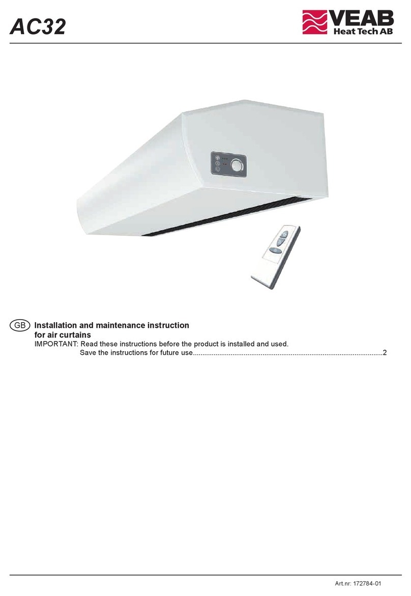
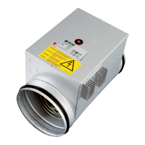
VEAB AC35 User manual

AC35
Art.nr: 172786-01
GB Installation and maintenance instruction
for air curtains
IMPORTANT: Read these instructions before the product is installed and used.
Save the instructions for future use.....................................................................................................2

2
AC35
Safety
• For all installations of electrically heated products
should a residual current circuit breaker 300 mA for
re protection be used.
• Keep the areas around the air intake and exhaust gril-
les free from possible obstructions!
• CAUTION! During operation the surfaces of the unit
can be hot!
• e unit must not be fully or partially covered with
clothing, or similar materials, as overheating can result
in a re risk! (E)
• e appliance can be used by children, aged from 8
years and above, and by persons (children included)
with reduced physical, sensory, or mental capabilities,
or lack of experience and knowledge, if they have been
given supervision or instruction concerning use of the
appliance in a safe way and understand the hazards
involved.
Children shall not play with the appliance.
Cleaning and user maintenance shall not be made
by children without supervision.
Children, of less than 3 years of age, should be kept
away unless continuously supervised.
Children, aged from 3 years and less than 8 years, shall
only switch on/o the appliance, provided that it has
been placed or installed in its intended normal opera-
ting position and they have been giving supervision or
instruction concerning use of the appliance in a safe
way and understand the hazards involved. Children,
aged from 3 years and less than 8 years, shall not plug
in, regulate and clean the appliance or perform user
maintenance.
General instructions
Read these instructions carefully before installation and
use. Keep this manual for future reference.
e product may only be used as set out in the assembly and
operating instructions. e guarantee is only valid if the pro-
duct is used in the manner intended and in accordance with
the instructions.
Application area
e AC35 air curtain unit is supplied with electrical
heating or hot water heating. AC35 is intended for en-
trances and smaller doors up to 3.5 metres in height.
Protection class for units with electrical heating: IP20.
Protection class for units with water heating: IP21.
Operation
Air is drawn in at the top/rear of the unit and blown out
downwards/outwards so that it shields the door ope-
ning and minimizes heat loss. To achieve the optimum
curtain eect the unit must extend the full height/width
of the door opening.e grille for directing exhaust air
is adjustable and is normally angled outwards to achieve
the best protection against incoming cold air.
e eciency of the air curtain depends on the air
temperature, pressure dierences across the doorway and
any wind pressure.
NOTE! Negative pressure in the building considerably
reduces the eciency of the air curtain. e ventilation should
therefore be balanced.
Mounting
e air curtain range includes possibilities for horizontal
installation and for vertical installation and the units can
also be installed recessed into suspended ceilings.
Horizontal mounting
e air curtain unit is installed horizontally with the
supply air grille facing downwards as close to the door as
possible. Minimum distance from outlet to oor for elec-
trically heated units is 1800 mm. For other minimum
distances, see g. 3.
For the protection of wider openings, several units can
be mounted next to each other using a joining kit
(g. 9).
Mounting with wall brackets PA34WB (g. 6)
1.1. Remove the plastic covers on the
wall brackets.
(Fig. 6A)
2. 2. Mount the brackets on the wall according to
measures in g. 6B.
3. 3. Fasten the hammer head screws on the unit in
the
holes M8. (Fig. 5 and 6C)
4. 4. Lock the nuts so that the hammer head screws
are
at 20 mm height. Note the direction of the screw
heads. (Fig. 6C)
5.5. Slide the unit on the consoles. (Fig. 6D)
6. 6. Lock the nuts against the bracket and put the
plastic
covers on again. (Fig. 6E)
Assembly and operating instructions

3
AC35
Horizontal mounting on the ceiling
readed rods, wire suspension kits and ceiling brackets
for ceiling mounting are available as accessories, see g.
7 and 8 and separate manuals.
Vertical mounting PL3JK
Units from 1,5 metres and longer may be used vertically.
For vertical mounting, all units must be supplemented
with a vertical kit containing everything needed for a
practical installation of oor standing units.
e unit can be reversed and placed on either side of the
door. Connections and PC Board PLS are positioned
near oor level when the air curtain is placed to the left
of the door and at the top when it is placed to the right
(seen from the inside).
e accompanying oor edging is attached to the oor
with fasteners appropriate to the surface.
Two units can be mounted directly on top of each other,
the oor edging is then used as a joining bracket.
e air curtain must be secured to wall or ceiling, use
PL3JK (accessory).
A design kit which gives a neater installation that
conceals cables and pipes is available as accessory, see
accessories pages.
See separate manual.
Electrical installation
e installation, which should be preceded by an om-
nipolar switch with a contact separation of at least 3
mm, should only be wired by a competent electrician
and in accordance with the latest edition of IEE wiring
regulations.
e control system is pre-installed in the air curtain with
an integrated control card, (see g. 2).
PLS is supplied pre-programmed with quick-t connec-
tions.
Modular cables are connected to the control board. See
manual for PLS.
Unit with water heating
Connected via the built-in PLS control board with
2 m cord and plug.
Unit with electrical heating
e installation is made on the top of the unit (horizon-
tal) or on the reverse (vertical).
Control supply is 230V~ and cable is routed from the
built-in PLS control board.
Power supply for heating (400V3N~) is connected to
terminal block in the internal connection boxes. 2-metre
and longer units require dual power supplies. e largest
cable diameter for the terminal block is 16 mm². e
cable glands used must meet the protection class require-
ments. In the distribution board it is to be indicated that
”the air curtains can be supplied from more than one
connection”.
See wiring diagrams.
Start-up (E)
Note! When using for the rst time or when starting up
after a long period of disuse, a small amount of smoke
and a slight odour may occur temporarily, which is
completely normal.
Type Output
[kW]
Voltage
[V]
Minimum area 2
[mm2]
AC35-10-E08 8400V3N~ 2,5
AC35-15-E12 12 400V3N~ 4
AC35-20-E1618 / 8 400V3N~ 2,5 / 2,5
AC35-25-E2018 / 12 400V3N~ 2,5 / 4
12 m and 2.5 m-units are connected with two power supplies, see p. 2. 2.5 meter units have elec-
tric batteries with two dierent eects, and the electric battery on the left, on a horizontal unit,
seen from inside the room, has the highest eect.
2Dimensioning of external wiring shall comply with applicable regulations and local deviations
may occur.

4
AC35
Connecting the water coil (W)
e installation must be carried out by an authorised
installer.
e water coil has copper tubes with aluminium ns and
is suitable for connection to a closed water heating sys-
tem. Steel connection pipe. e heating coil must not be
connected to a mains pressure water system or an open
water system.
Note that the unit shall be preceded by a regulating
valve, see valve kits.
e water coil is connected on top of the unit (horizontal
mounting) or on the reverse (vertical mounting) via con-
nections DN20 (3/4’’), external thread. Flexible hoses are
available as an accessory, see accessories pages.
e connections to the heating coil must be equipped
with shut o valves (included in valve kits) to allow pro-
blem free removal.
A vent valve should be connected at a high point in the
pipe system. Air valves are not included.
For vertical installation and bottom water connection it
is not possible to bleed the coil in the unit. Ensure that
the water coil is lled with water and that no air re-
mains, prior to commissioning. See g. 4.
Our recommended solution is to use a T-connection and
shut o valves. Small air bubbles may remain, but will
disappear with normal operation.
NOTE: Care must be taken when connecting
the pipes. Use a wrench or similar to hold the
air curtain connections to prevent straining
of the pipes and subsequent water leakage
during connection to water supply pipe-work.
Adjustment of the air curtain and air ow
e direction and speed of the air ow should be ad-
justed considering the load on the opening. Pressure
forces aect the air stream and make it bend inwards
into the premises (when the premises are heated and the
outdoor air is cold).
e air stream should therefore be directed outwards to
withstand the load. Generally speaking, the higher the
load, the greater the angle that is needed.
Basic setting fan speed
e fan speed when the door is open is set using the
control. Note that the air ow direction and fan speed
may need ne adjustment depending on the loading of
the door.
Filter (W)
e water coil is protected against dirt and blockage by
an air lter which covers the coil face. In environments
where the lter needs cleaning often, it is advisable to
use an external intake lter (see accessories pages), which
provides an easier maintenance, since the unit does not
need to be opened.
Service, repairs and maintenance
For all service, repair and maintenance rst carry out the
following:
1. Disconnect the power supply.
2. Loosen the screws and raise the front panel.
e front is blocked in open position with the front
hatch hook, see g 1A or removed completely, see
g. 1B. e service hatch is removed by loosening
the screws.
3. After service, repairs and maintenance fasten the
service hatch and the front. When the front has been
removed it is important to be sure it is rmly seated
in the front locks again, see g. 1B.

5
AC35
Maintenance
Unit with water heating:
e appliance lter should be cleaned regularly to ensure
the air curtain eect and the heat emission from the
device. How often depends on local circumstances.
A clogged lter is not a risk, but the appliance function
can fail.
1. Disconnect the power.
2. Loosen the screws and raise the front panel.
e front is blocked in open position with the front
hatch hook, see g 1A.
3. Remove the lter and vacuum clean or wash it.
If the lter is clogged or damaged, it may need to
be changed.
All units:
Since fan motors and other components are maintenance
free, no maintenance other than cleaning is necessary.
e level of cleaning can vary depending on local condi-
tions. Undertake cleaning at least twice a year. Inlet and
exhaust grilles, impeller and elements can be vacuum
cleaned or wiped using a damp cloth. Use a brush when
vacuuming to prevent damaging sensitive parts. Avoid
the use of strong alkaline or acidic cleaning agents.
Overheating
e air curtain unit with electric heater is equipped with
an overheat protector. e overheat protection is reset by
turning o the switch and the unit cools. If it is deploy-
ed due to overheating, reset as follows:
1. Disconnect the electricity with the fully
isolated switch.
2. Allow the electrical coil to cool.
3. Determine the cause of overheating and rectify
the fault.
4. Connect the air curtain again.
All motors are equipped with an integral thermal safety
cut-out. is will operate, stopping the air curtain
should the motor temperature rise too high. e cut-out
will automatically reset when the motor temperature has
returned to within the motor’s operating limits.
Temperature control
Temperature control of PLS maintains the exhaust tem-
perature to approx. +40 °C. If the temperature should
exceed anyway there is an overheating alarm. For more
information see the manual for PLS.
Fan replacement
1. Determine which of the fans is not functioning.
2. Disconnect the cables to the relevant fan.
3. Remove the screws securing the fan and lift
the fan out.
4. Install the new fan as above in reverse order.
Replacing a electric coil (E)
1. Mark and disconnect the cables to the electric
coil package.
2. Remove the mounting screws securing the electric
coil package in the unit and lift it out.
3. Replace faulty electric coil.
4. Install the electric coil package in reverse order
to the above.
Replacing the water coil (W)
1. Shut o the water supply to the unit.
2. Disconnect the connections to the water coil.
3. Remove the mounting screws securing the coil
in the unit and lift the coil out.
4. Install the new coil in reverse order to the above.
Draining the water coil (W)
e drain valves are on the underside of the coil on the
connector side. It can be accessed via the service hatch.

6
AC35
Trouble shooting
If the fans are not working or do not blow properly, check
the following:
at the intake grille/lter is not dirty.
Check the functions and settings of the control system
PLS, see manual for PLS.
If there is no heat, check the following:
Check the functions and settings of the control system
PLS, see manual for PLS.
For units with electrical heating, check also the following:
Power supply to electric heater coil; check fuses and
circuit-breaker (if any).
at the overheat protection for the motors has not been
deployed.
For units with water coil, check also the following:
at the water coil is air free.
at there is enough water ow.
at incoming water is heated enough.
If the fault cannot be rectied, please contact a qualied
service technician.
Residual current circuit breaker (E)
When the installation is protected by means of a residual
current circuit breaker, which trips when the appliance
is connected, this may be due to moisture in the heating
element. When an appliance containing a heater element
has not been used for a long period or stored in a damp
environment, moisture can enter the element.
is should not be seen as a fault, but is simply rectied
by connecting the appliance to the mains supply via a
socket without a safety cut-out, so that the moisture can
be eliminated from the element. e drying time can
vary from a few hours to a few days. As a preventive
measure, the unit should occasionally be run for a short
time when it is not being used for extended periods of
time.

7
AC35
528
L
275 33
PL3510/3515: 4 M8
PL3520: 6 M8
PL3525: 8 M8
DN20 (3/4”),
outside thread
160
A
43 205 92
364
40
PLS
2 m; 2,5 m
L1
528
275
40
23
L
(mm)
A
(mm)
AC35-10 1073 72
AC35-15 1583 72
AC35-20 2073 74
AC35-25 2583 71
L1
(mm)
AC35-15 1589
AC35-20 2079
AC35-25 2589
AC 35-10/35-15: 4 M8
AC35-20: 6 M8
AC35-25: 8 M8

8
AC35
PLS
2
1
Fig. 1A
Open the unit by raising the front panel. The front is
blocked in open position with the front hatch hook.
Fig. 2
Control card PLS is integrated in the air
curtain at delivery.
Fig. 1B
When the front has been removed it is important to be
sure it is rmly seated in the front locks again.
100
Fig. 3
Minimum distance.

9
AC35
AB
A
160L
B
160875
875
AB
160770
74
57
45
Fig. 5
M8-holes for mounting.
Fig. 4
BA
34
Filling the water coil
L
(mm)
AC35-10 750
AC35-15 1260
A B
AC35 205 92
12

10
AC35
Fig. 6
See separate manual for PA34WB.
AC35 + PA34WB
20 mm
79
19
120
11
40
PA34WB
AC35-W-15 2 pcs
AC35-W-20 3 pcs
AC35-W-30 4 pcs
A
B
D
E
C
F

11
AC35
PL3JK
PA34WS
(PA34CB)
PA34TR
PA34CB
Fig. 7
PA34TR + PA34CB.
See separate manual for PA34TR.
Fig.8
PA34WS + PA34CB
See separate manual for PA34WS.

12
AC35
Note! The top of the air
curtain must be secured
in the wall or ceiling.
Fig. 9
See separate manual for PL3JK
PL3JK

13
AC35
Accessories Horizontal
PL3JK
Accessories Vertical
PA34WB15
Wall bracket for 1 and 1.5
meter unit
Units: 2 pcs
AC35-10/15 Fig. 6
Brackets for mounting the unit
horizontally on the wall.
Length: 400 mm
PA34WB20 Wall bracket for 2 meter unit
Units: 3 pcs AC35-20 Fig. 6
PA34WB30
Wall bracket for 2.5-meter
unit
Units: 4 st
AC35-25 Fig. 6
PA34CB15 Ceiling brackets for 1 and 1.5
meter unit Units: 4 pcs AC35-10/15 Fig. 7/8
Ceiling brackets for mounting the
unit on the ceiling using wires or
threaded rods (not included).
PA34CB20
Ceiling brackets for 2 meter
unit
Units: 6 pcs
AC35-20 Fig. 7/8
PA34CB30
Ceiling brackets for 2.5 meter
unit
Units: 8 pcs
AC35-25 Fig. 7/8
PA34WS15
Wire suspension kit for 1 and
1.5 meter units
Units: 4 pcs
AC35-10/15 Fig. 8
Wire suspension kit with
bright-galvanized wires with
wire locks for ceiling installa-
tion. Used with ceiling mounts
(PA34CB15/20/30).
Length: 3 m
PA34WS20
Wire suspension kit for
2 meter units
Units: 6 pcs
AC35-20 Fig. 8
PA34WS30
Wire suspension kit for
2.5 meter units
Units: 8 pcs
AC35-25 Fig. 8
PA34TR15
Threaded rods for 1 and 1.5
meter unit
Units: 4 pcs
AC35-10/15 Fig. 7
Threaded rods for ceiling moun-
ting.
Used with ceiling mounting
brackets PA34CB.
Length: 1 m
PA34TR20 Threaded rods for 2 meter unit
Units: 6 pcs AC35-20 Fig. 7
PA34TR30
Threaded rods for 2.5 meter
unit
Units: 8 pcs
AC35-25 Fig. 7
PL3JK Connecting bracket with
mounting hardware AC35 Fig. 9
For joining together horizontal
air curtains. Provides a neat and
uniform installation.
Also used for vertical mounting.
PL3JK Vertical kit for AC35 AC35 Fig. 9
Used to adapt a unit for vertical mounting. Contains
oor edging and mounting hardware to brace the
top. The vertical kit makes it possible to mount two
units on top of each other. One vertical kit is requi-
red per unit. Also used as a connecting bracket for
horizontal mounting.
AXP300 Collision guard AC35 Floor positioned guard against collisions
with, e.g., a shopping trolley.
PA34WB
PA34CB
PA34WS
PA34TR
PL3JK
AXP300

14
AC35
PAMLK
VAT
Accessories PLS
PLSB
PLSAC
PLSRTX
SIRECC
SIRECJ4 / SIRECJ6
VOS
VOT
Type Connection
VOS15LF DN15
VOS15NF DN15
VOS20 DN20
VOS25 DN25
VOT15 DN15
VOT20 DN20
VOT25 DN25
VAT
Control valves for water systems (optional)
PLSB Control unit Basic Incl. control unit PLSUB1 and 5 meter modular
cable with RJ12 quick connect.
IP30
PLSAC Control unit Competent Incl. PLSUA1 control unit, box cover, PLSC1X hub
unit, PLSDC door switch, and 2 modular cables
with RJ12 quick connects (1 pc 3 m, 1 pc 5 m).
IP30
PLSRTX External room
temperature sensor
70x33x23 mm
SIRECJ4 RJ11 coupler (4/4) Used to join together two RJ11 or RJ12 connec-
tors.
SIRECJ6 RJ12 coupler (6/6)
SIRECC403
RJ11 modular cable (4/4)
Length 3 m
SIRECC405 Length 5 m
SIRECC410 Length 10 m
SIRECC415 Length 15 m
SIRECC603
RJ12 modular cable (6/6)
Length 3 m
SIRECC605 Length 5 m
SIRECC610 Length 10 m
SIRECC615 Length 15 m
PAMLK Motor alarm board Provides a potential free alarm connection
when thermal contact is triggered in the motor.
Installed in the air curtain.

15
AC35
AC35-E
3510E 3520E/3525E
3510E/3515E
400V3~
PLSB1
400V3~
Actuator
230V~
Transformer
230V
200V
170V
145V
120V
100V
N
Black
Black
Grey
Blue
Blue
White
White
C2 C1 ROOM
Internal
sensor
Motor
protection
°C°C°C
Transformer
230V
200V
170V
145V
120V
100V
N
Yellow
Orange
Red
Brown
Black
Green
Blue
N N
3515E
°C°C°C°C
3525E 3520E
230V~

16
AC35
AC35-W
PLSB1
230V~
Actuator
230V~
Transformer
230V
200V
170V
145V
120V
100V
N
Black
Blue
White
White
Supply
230V~
C2 C1 ROOM
Internal
sensor
Motor
protection
Transformer
230V
200V
170V
145V
120V
100V
N
Yellow
Orange
Red
Brown
Black
Green
Blue
3510W
°C°C°C
3515W
°C°C°C°C
3225W 3520W

17
AC35
PLS Basic
AC35-E
PLS Basic - Parallel connection
Wiring diagrams for PLSAC Competent, see manuals for PLS.
230V~ 230V~
C2
X5
C1
X4
ROOM
X3
Pot.
Unit ID
N L
PE
NL
PE
ACTUATORSUPPLY
C2
X5
C1
X4
ROOM
X3
Pot.
Unit ID
N L
PE
NL
PE
ACTUATORSUPPLY
PLSB1 PLSB1
PLSRTX
(optional)
PLSUB1
230V~
C2
X5
C1
X4
ROOM
X3
Pot.
Unit ID
N L
PE
NL
PE
ACTUATOR SUPPLY
PLSB1 PLSRTX
(optional)
PLSUB1

18
AC35
PLS Basic
AC35-W
C
C2
X5
C1
X4
ROOM
X3
Pot.
Unit ID
N L
PE
NL
PE
ACTUATOR SUPPLY
230V~
PLSB1
SD230 PLSRTX
(optional)
PLSUB1

19
AC35
PLS Basic - Parallel connection
AC35-W
Wiring diagrams for PLSAC Competent, see manuals for PLS.
C2
X5
C1
X4
ROOM
X3
Pot.
Unit ID
N L
PE
NL
PE
ACTUATOR SUPPLY
C2
X5
C1
X4
ROOM
X3
Pot.
Unit ID
N L
PE
NL
PE
ACTUATOR SUPPLY
C2
X5
C1
X4
ROOM
X3
Pot.
Unit ID
N L
PE
NL
PE
ACTUATOR SUPPLY
230V~
230V~
230V~
PLSB1 SD230
SD230
SD230
PLSB1
PLSB1 PLSUB1
PLSRTX
(optional)

VEAB Heat Tech AB
Box 265
S-281 23 Hässleholm
SWEDEN
Visitors adress
Stattenavägen 50
Delivery adress
Ängdalavägen 4
Org.no/F-skatt
556138-3166
VAT.no
SE556138316601
Postal Cheque Service
48 51 08- 5
Bank Transfer
926-0365
Fax
Int +46 451 410 80
E-mail
veab@veab.com
Phone
Int +46 451 485 00
Website
www.veab.com
NB: We reserve us from typographical errors and the right to make changes and improvements to the contents of this manual without prior notice.
AC35
20
Table of contents
Other VEAB Heater manuals

VEAB
VEAB CV MTEM Series User manual

VEAB
VEAB CV MQU Series User manual

VEAB
VEAB VFLPG User manual

VEAB
VEAB CV MTC Series User manual

VEAB
VEAB EA Series User manual

VEAB
VEAB CV TX Series User manual

VEAB
VEAB KX 2 User manual

VEAB
VEAB ENV-L Series User manual

VEAB
VEAB VFLPG Series User manual

VEAB
VEAB CV MQEM Series User manual