Cervoz MEC-COM-2032i User manual

MEC-COM-2032i
M.2 2242/2260/2280 2-port RS-232/422/485 isolated serial board
User’s Manual
First Edition, December 2021
© 2021 Cervoz Technology Co., Ltd. All rights reserved.
Reproduction without permission is prohibited

2
M.2 2242/2260/2280 Serial Card
User’s Manual
The software described in this manual is furnished under a license agreement and may be
used only in accordance with the terms of that agreement.
Copyright Notice
© 2021 Cervoz Technology Co., Ltd. All rights reserved. Reproduction without permission is
prohibited.
Trademarks
Cervoz is a registered trademark of Cervoz Technology Co., Ltd. All other trademarks or
registered marks in this manual belong to their respective manufacturers.
Disclaimer
Information in this document is subject to change without notice and does not represent a
commitment on the part of Cervoz.
Cervoz provides this document “as is,” without warranty of any kind, either expressed or
implied, including, but not limited to, its particular purpose. Cervoz reserves the right to make
improvements and/or changes to this manual, or to the products and/or the programs
described in this manual, at any time.
Information provided in this manual is intended to be accurate and reliable. However, Cervoz
assumes no responsibility for its use, or for any infringements on the rights of third parties that
may result from its use.
This product might include unintentional technical or typographical errors. Changes are
periodically made to the information herein to correct such errors, and these changes are
incorporated into new editions of the publication.
Technical Support Contact Information
http://www.cervoz.com/contact.php
Cervoz Technology Co., Ltd.
Tel: +886-2-2911-9599
Fax: +886-2-2911-9566

3
Table of Contents
Chapter 1
Introduction
4
Overviews
4
Features
4
Installation Flowchart
5
Package Checklist
5
Chapter 2
DIP Switch Setting
6
Chapter 3
Hardware Installation
8
Chapter 4
Driver Installation
12
Appendix
Pin Assignments
18
Board Side Pin Assignments
18
Device Side Pin Assignments
19
Technical Reference
20
MEC-COM-2032i Specifications
20
MEC-COM-2032i Dimensions
21
Product Warranty Statement
22

4
1
Introduction
Overview
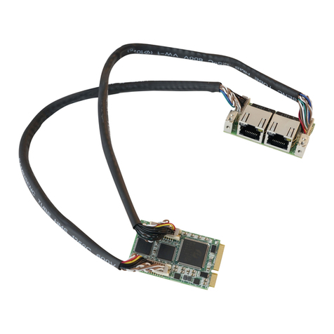
MEC-COM-2032i is a serial communication card for embedded PC. The card follows
the M.2 standard which is complaint with PCI Express x 1 classification and M.2 form
factor. This board fits in any host computer that has M.2 slots.
Features
The PCI Express boards have the following outstanding features:
Single-Lane (x1) PCI-Express with throughput up to 5.0 / 2.5Gbps
Fully compliant with PCI-Express Base Specification Rev 2.0
Top serial transmission performance up to 921.6 Kbps baud rate
FIFO 256 Bytes, 15 KV ESD protections on board
H/W, S/W automate flow control supported
RS-232/422/485 mode selectable by DIP switch setting
Support port to computer isolation 2.5kV

5
Installation Flowchart
Installation Flowchart of MEC-COM-2032i
The following flowchart provides a brief summary of the procedure you should follow to
install the M.2 card:
Package Checklist
The following items are included in the M.2 board package:
M.2 Card x 1
Bracket x 1
20Pin Internal Cable w/ two DB9 Male Connectors (30cm) x 1
Quick Installation Guide (Printed) x 1
Note: Notify your sales representative if any of the above items are missing or
damaged.
Set up DIP switch
Hardware Installation
Connect the internal cable
Install the card in the M.2 slot
Hardware Installation
Connector Fixation
Hardware Installation
DIP Switch Setting
Install the driver
Software Installation

6
2
DIP Switch Setting
Set up the DIP switch
Make sure you set up the correct DIP switch before hardware installation
DIP Switch Define

7
Mode Select
SW1: PORT 1 RS232/RS422/RS485 MODE Select switch
SW2: PORT 2 RS232/RS422/RS485 MODE Select switch
**SW1 and SW2 are the same way to set up.
RS232
RS422
RS485
Switch 1
ON
ON
OFF
Switch 2
OFF
ON
ON
Make sure you set up the correct DIP switch before hardware installation

8
3
Hardware Installation
This chapter describes the PCI Express Series hardware installation procedure. Since the
BIOS automatically assign the PCI Express board’s IRQ number and I/O addresses, you must
plug in the board before installing the driver.
Step 1
Connect the internal cable to the card

9
Step 2
Install the card to the M.2 slot
Make sure you install the card in the right position (fool-proof design)
Step 3
Fix the card on the motherboard
Make sure you tighten up the screws to fix the card

10
Step 4
Card installation completed

11
Connector Fixation
1. Standard PCI/PCIe Bracket
PCI / PCIe IO Bracket
2. Customized Front / Rear Plate
Front / Rear I/O Plate
Universal Bracket

12
4
Driver Installation
This chapter describes the procedures of installation, configuration and update/removal the
driver on Windows 10.
Step 1
Turn on PC and start Windows
Please download driver from Cervoz website.
1. To ensure the installation of hardware device.
Note
Win 10 OS as example

13
Step 2
Windows automatically detects the new device
1. Start Computer Management and click device manager.
2. Look for the PCI Serial Port.
Step 3
Update driver –PCI Serial Port
1. Right click on “PCI Serial Port”and click “Update Driver”.

14
Step 4
Install driver
1. Select “Browse”and choose “MEC-COM(RS232)”.
2. Locate your driver (base on your system).
3. Click “Next” and it will attempt to install the driver.
Step 5
Update driver –Multifunction Device
Multi-port serial adapters: Exar’s 2-Port UART PCI-Express Card completed and
update “Multifunction Device”.

15
Step 6
Install driver
1. Select “Browse”.
2. Locate your driver (base on your system).
3. Click “Next” and it will attempt to install the driver.
Step 7
Driver installation completed
You will see the COM ports listed on the device manager if the installation is success.

16
Step 8
Set up the COM ports
1. Select the COM port and right click.
2. Select “Properties”.
Step 9
COM ports properties settings
1. Properties settings window would pop out.
2. Select the “Port Setting”page.

17
Step 10
Select COM ports hardware configuration
Click “RS-485”to select the hardware configuration for your COM port (RS422/485).
Note
Default setting of the COM port is RS232

18
Appendix
Pin Assignments
Board Side Pin Assignments
Wire to Board Connector (CN1)
Pin
Description
Pin
Description
1
DCD_1
2
DCD_2
3
DSR_1
4
DSR_2
5
RXD_1
6
RXD_2
7
RTS_1
8
RTS_2
9
TXD_1
10
TXD_2
11
CTS_1
12
CTS_2
13
DTR_1
14
DTR_2
15
RI_1
16
RI_2
17
NC
18
NC
19
GND
20
GND

19
Device Side Pin Assignments
RS232/422/485 Port DB9 Male Connector-1
Pin
RS232
Description
RS-422/485 FULL DUPLEX
Description
RS-485 HALF DUPLEX
Description
1
DCD_1
TX_1-
DATA_1-
2
RxD_1
TX_1+
DATA_1+
3
TxD_1
RX_1+
4
DTR_1
RX_1-
5
GND
6
DSR_1
7
RTS_1
8
CTS_1
9
RI_1
RS232/422/485 Port DB9 Male Connector-2
Pin
RS232
Description
RS-422/485 FULL DUPLEX
Description
RS-485 HALF DUPLEX
Description
1
DCD_2
TX_2-
DATA_2-
2
RxD_2
TX_2+
DATA_2+
3
TxD_2
RX_2+
4
DTR_2
RX_2-
5
GND
6
DSR_2
7
RTS_2
8
CTS_2
9
RI_2

20
Technical Reference
MEC-COM-2032i Specifications
General
PCI-Express Revision
PCI-Express Base Specification Rev 2.0
PCI-Express
Electromechanical
Revision
PCI-Express M.2 Electromechanical Rev. 1.1
Hardware
Controllers
XR17V352 (16C550C compatible)
Bus
Single-Lane (x1) PCI-Express with throughput up to 5.0 / 2.5Gbps
Interface (Connector)
RS-232/422/485
2 (DB9 male)
Serial Line Protection
ESD Protection
15 KV on board
Galvanic Isolation
Voltage
2.5kV
Performance
Baud Rate
Asynchronous baud rates up to 921.6 Kbps
Serial Communication Parameters
Data Bits
5, 6, 7, 8
Stop Bits
1, 1.5, 2
Parity
No Parity bit
Odd Parity bit
Even Parity bit
Parity bit forced to 1
Parity bit forced to 0
Flow Control
RTS/CTS, XON/XOFF
Serial Signals
RS-232
TXD, RXD, RTS, CTS, DTR, DSR, DCD, GND
RS-422
TXD+, TXD-, RXD+, RXD-
RS-485
DATA+, DATA-
Driver Support
Operating Systems
Win 7, Win 8, Win 10
Power Requirement
Power Consumption
Dimensions
Width x Length (mm)
22.00 x 42.00 / 22.00 x 60.00 / 22.00 x 80.00
Environmental Limits
Operating Temperature
-40°C ~ 85°C
Storage Temperature
-40°C ~ 95°C
Humidity
5% ~ 95%
Regulatory Approvals
EMC
CE, FCC
EMI
EN 55022, EN61000-3-2, EN61000-3-3, FCC Part 15 Subpart B
Class B
EMS
EN 55035, IEC 61000-4-2, IEC 61000-4-3, IEC 61000-4-4,
IEC 61000-4-5, IEC 61000-4-6, IEC 61000-4-8, IEC 61000-4-11
IEC-60950
Reliability
Warranty
3 years
Table of contents
Other Cervoz Computer Hardware manuals