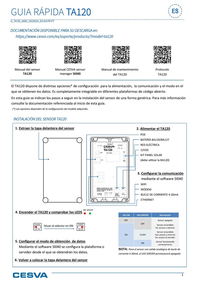
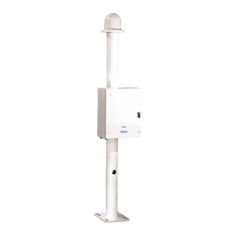
CESVA TA120 User manual

TA120
Noise sensor
USER GUIDE
M_TA120_v0028_20211020_EN


1
Since its beginnings in Barcelona in 1969, has been devoted to
manufacturing sound equipment and instrumentation through research,
development and innovation, and by registering its own patents.
We belong to national and international committees for the establishment and
revision of standards and regulations.
has a fast and efficient distribution network in over 40 countries
around the world.
We offer our customers an after-sales service to ensure the long life of our
instruments. Periodic tests and calibration services are also available.
Our website is the focal point for finding information on our products, requesting
no-obligation quotes, downloading software, contacting us andbeing keptupdated
about all the training events and exhibitions we are present at on a regular basis.
Taking care of our customers and listeningto what they tell us means we are closer
to them and are able to offer the measurement solution thatfully meets their needs.

2 Contents
1. Equipment and literature 4
2. General device description 5
2.1 TA120 noise sensor 5
2.2 Main features of TA120 sensor 5
2.3 Device components 6
2.4 SI040 - CESVA Sensor Manager Software 8
3. Installing TA120 sensor 9
3.1 Steps 9
3.2 Cable gland inputs 11
4. TA120 communication for data transmission 13
4.1 Ethernet 13
4.2 Wi-Fi* (WF120 Optional module) 14
4.3 Modem 3G/GPRS* (MR123 Optional module) 14
4.4 Current Loop 4-20mA* (CL120 Optional module) 15
4.4.1 Description of a 4-20mA current loop circuit 16
5. TA120 sensor power 17
5.1 Mains 17
5.2 12VDC Input 18
5.3 PoE (Power Over Ethernet) 18
5.4 BA120/BA127 battery* 19
5.5 PS120 Solar Panel kit 20
6. Acoustic verification 21
6.1 Remove the front cover and outdoor kit TK120 21
6.2 Connecting the PC to the sensor TA120 22
6.3 Place the calibrator 24
6.4 Check the setting 25
6.5 Close and secure the sensor 26
7. Maintenance 28
8. Technical specifications 30
8.1 NOISE MEASUREMENT ACCORDING TO IEC 61672-1 30
8.2 MICROPHONE 30
Contents

Contents 3
8.3 WARM-UP TIME 31
8.4 PROTECTION AGAINST EXTERNAL AGENTS 31
8.5 CONNECTIVITY 31
8.6 OPTIONAL CONNECTIVITY 31
8.7 TRANSMISSION PROTOCOLS 31
8.8 REMOTE CONTROL 32
8.9 POWER 32
8.10 ENVIRONMENTAL CRITERIA 32
8.11 DIMENSIONS AND WEIGHT 33
8.12 MARKING 33
8.13 OPTIONS* 33

4 Chapter 1 Equipment and literature
The first step is to check that all the equipment and literature supplied with the
device is there:
Material included:
•Noise sensor TA120, composedby its centralbody, and an outdoor kittoprotect
the microphome.
•USB cable type B.
•Connectors for net mains cable and 12VDC and Ethernet communication cable.
•Cap for input cable gland.
Literature included:
•TA120 noise sensor user’s manual.
•Warranty.
Should any of these elements be missing, please contact your official distributor.
Equipment and literature
1. Equipment and literature
1

Chapter 2 General device description 5
This chapter provides a general description of the TA120 noise sensor. This
description will introduce you to all the possibilities offered by the TA120 and its
main features. It will also help you to identify the various components of the device.
2.1 TA120 noise sensor
The TA120 sensor is the solution for monitoring noise levels of infrastructures and
activities. The TA120 brings in a small size equipment, the Class 1 sound level
meter precision, the maximum protection of TK200 a professional outdoorkit (rain,
snow, wind, dust, birds, IP65) and full connectivity with open source platforms and
industrial protocols.
2.2 Main features of TA120 sensor
The most important features of TA120 sensor are as follows:
•Class 1 precision sensor according to IEC 61672-1.
•Protection against external agents with outdoor kit TK120: wind, rain, birds.
Maintains Class 1. IP65 Protection.
•Can be fully integrated into different open source platforms for sensors
connectivity.
•Light weighted small sized and easy to install in street lights, marquees,
billboards, shelters, kiosks and advertising posts.
•Powered by mains, POE (Power over Ethernet), 12 VDC (optional PS120 Solar
panel kit, external batteries), public lighting network with optional BA120 daily
backup battery*.
•Continuous measurement 24 hours / 7 days a week.
•Minimum annual maintenance. The materials used in manufacturing the TA120
ensure a long life.
•Removable outdoor kit for quick verification and adjustment with an acoustic
calibrator (IEC 60942).
•Communication by Ethernet (RJ45) or other options: 3G/GPRS Modem, Wi-Fi,
Current loop (4-20 mA loop).
General device description
2. General device description
2

6 Chapter 2 General device description
2.3 Device components
1. TK120 Outdoor Kit · Responsible for protecting the microphone and
preamplifier of possible meteorological factors: wind, snow, rain, etc.
2. Screws ·4 screews to close the front cover of the main body [3].
3. Main body · Maintains the IP65 when it is closed. Inside contains the elements
which are described between points [5] and [18].
4. Gland cable input for TA120 communication.
5. Gland cable input for TA120 supply.
6. LED ON indicator · It indicates whether the device is supplied.
7. LED SERVER indicator · It indicates the connection with the server.
8. USB connector · Type B connector for digital communication with a PC.
Compliant with USB rev. 2.0.
9. LAN connector for Ethernet connection.
10. Connector for 4-20mA current loop / Slot for SIM card.
11. Marks · CE mark (European conformity mark) and WEEE mark (Indicates the
separate collection of electrical/electronic appliances.).
12. POWER ON/OFF switch · To turn on and turn off the TA120 sensor.
13. Connector to connect the battery* optional BA120/BA127.
14. Equipment information ·This area displays the serial number of the sensor
and also its MAC address.
15. Battery support optional BA120/BA127.
16. Mains power connector ·100-240V 50/60Hz.
17. 12VDC power connector ·Power through solar panels and 12V external
batteries and PS120 solar panel kit (BA120 battery* required).
18. Information of power connectors [16] and [17].

Chapter 2 General device description 7

8 Chapter 2 General device description
2.4 SI040 - CESVA Sensor Manager Software
CESVA Sensor Manager is the software to verify and set the TA120 noise
sensor. In order to communicate with the sensor, two software applications
should be installed:
1. Install the drivers package with the CESVA USB Drivers software,
version 1.01 or later.
2. Install the CESVA Sensor Manager software.
If you already have an older version of CESVA Sensor Manager or CESVA USB
Driver installed in your computer, first uninstall the old version before installing
the new one.
NOTE: Download the latest versions of CESVA Sensor Manager and CESVA
USB Drivers from (www.cesva.com), you will find these softwares
in the support section of the TA120 sensor. This will ensure you are installing
the latest versions.

Chapter 3 Installing the TA120 sensor 9
3.1 Steps
1. Preferably, mount the sensor vertically using its support and flanges. The
TA120 support also allows the sensor to be mounted horizontally.
Installing the TA120 sensor
3. Installing TA120 sensor
3

10 Chapter 3 Installing the TA120 sensor
2. Unscrew the 4 screws [2] of the front of the sensor box and remove the box
cover.
3. Set TA120 communication for data transmission (see Chapter 4).
4. Feed the TA120 sensor (see Chapter 5).
5. Place the switch POWER [12] in the ON position. Check that the LED [6] has
been turned ON (red). If it is not lit, there is a problem in the power supply: check
the external power and that the switch POWER [12] is in the ON position.
6. Wait 5 minutes and check that the LED SERVER [7] is lit (green). If it is not lit,
there is a problem with the data server or router configuration, AP (Access Point)
or Internet access: MAC address, DHCP enabled, etc. In that case, consult your
installer or router provider or AP.
For TA120 sensor with current loop analog output configuration of 4-20 mA, the
SERVER LED [7] will always be turned off.
If the SERVER LED [7] is lit, the sensor is working properly. Close the sensor
box by the 4 screws [2] of the front cover.

Chapter 3 Installing the TA120 sensor 11
3.2 Cable gland inputs
In the bottom part of the TA120 there are two cable gland inputs [4 and 5] to
introduce the necessary cables for power thesensor andfor communication thereof
if necessary (depending on configuration).
The gland connector has the following elements:
[Cap] [Seal] [Sealing nut]
- Cap to close the cable gland input which will not be use.
- Seal Consisting of two concentric rubber rings to seal the cable introduced by
the cable gland input.
- Sealing nut to close the cable gland input.
Follow these steps to enter the power and / or communication cables in the
corresponding input cable glands:
1) If there is a cap, remove it and then unscrew the sealing nut.
2) Pass the power / communication cable by the corresponding input cable gland.
If the thickness of the cable does not allow to insert the cable, push the Seal
part with a thin and elongated tool by pushing from the inside of the TA120
central body [3].
NOTE: In case that only one of the two inputs cable gland is used, place the
supplied cap on the unused input to maintain IP65 sensor protection.

12 Chapter 3 Installing the TA120 sensor
Once the Seal is out, separate the two concentric rubber rings and insert just
the external rubber ring from the outside of the TA120 central body [3].
→→
3) Insert the cable first trough the sealing nut and then through the input
gland.The cable should not have the connector due the connection between
the cable and its connector will be done after the cable is entered through the
input cable gland.
4) Finally place the respective connectorto the
cable already introduced by the input cable
gland, and plug in the connector on the main
body of sensor TA120.

Chapter 4 TA120 communication for data transmission 13
Depending on the configuration of the acquired model, there are several options
for data transmission:
4.1 Ethernet
To make an Ethernet communication insert the LAN cable without RJ45 connector
through the bottom input cable gland [4], then crimp the cable. See chapter 3.2 for
more information about insert the cable through the appropriate cable gland input.
TA120 communication for data
transmission
4. TA120 communication for data transmission
4

14 Chapter 4 TA120 communication for data transmission
Connect the LAN cable between the RJ45 [9] connector and the corresponding
router or AP (Access Point). Take care to put the cable in a "U" shape under the
TA120 sensor for, in case of rain, avoid possible water dripping into the box.
Use CESVA Sensor Manager software - SI040 if you need configure the server
where TA120 sensor data will be sent and / or if you want to set a static IP address.
For this, consult the manual or software help.
4.2 Wi-Fi* (WF120 Optional module)
Through the USB output [8] and the SI040–CESVA Sensor Manager software you
should seek the wireless network to connect the TA120 sensor. For this, consult
the manual or software help.
4.3 Modem 3G/GPRS* (MR123 Optional module)
Through the USB [8] CESVA Sensor connection and SI040-software Mananger,
configure the parameters of the internal 3G/GPRS modem of the TA120. For this,
consult the manual or software help.
NOTE: only recommends the use of SIM cards with a flat rate
contract. Other types of cards, for example prepaid, can give problems.
NOTE: recommends the use of SIM cards from telephone
companies that have their own infrastructures near the measurement area of
the TA120 sensor.

Chapter 4 TA120 communication for data transmission 15
4.4 Current Loop 4-20mA* (CL120 Optional module)
Analog output via 4-20mA current loop. Insert the communication cable through
the bottom gland input [4], then connect the cable to the 4-20 mA current loop
connector [10]. See chapter 3.2 for more information about insert the cable through
the appropriate gland input.
Technical characteristics of the current output:
Power
from 8 to 36 VDC
Output
from 4 to 20 mA / from 25.0 to 125.0 dBA
LAeqT=Iout-4100
16 +25 dBA
Note 1: Iout is the output current in mA
Note 2: Measurement range is from 35.0 to 120.0 dBA
Note 3: T is the programmed time averaged. The output current is updated every T(*).
Note 4: If an overload occurs, LAeqT > 124.5 dBA
Maximum error
±0.2 dB, respect to the measured level
Connection
Without polarity
(*) Configurable parameter through SI040 - CESVA Sensor Manager software. For more information consult the
manual or the software or help.

16 Chapter 4 TA120 communication for data transmission
4.4.1 Description of a 4-20mA current loop circuit
A typical 4-20mA current-loop circuit is made up by next elements: a sensor
(TA120); a power supply for the loop; and a receiver (to read the information).
These elements are connected in a closed, series circuit, loop.
The sensor output transmits the proportional 4-20mA dc-current that circulates
within the closed series-loop. The 4 mA represents the sensor’s lowest level output,
and 20 mA representing the sensor’s highest level output.
The receiver, normally a data acquisition system, converts the 4-20mA current back
into a voltage which can be further processed and/or displayed.
Current loops are ideal for data transmission because of their inherent insensitivity
to electrical noise. In a 4-20 mA current loop, all the current flows through all
components.

Chapter 5 TA120 sensor power 17
Depending on the purchased model configuration, there are several options to
power the TA120 sensor:
5.1 Mains
Connect the power cable to the mains (make sure it meets the specifications
described in section 8.9). Take care to put the cable in a "U" shape under the
sensor, in case of rain, this will avoid possible water dripping into the box. Refer to
Section 3.2 for more information about insert the cable through the appropriate
gland input.
Connect the power cable to the A.C. INPUT [16] of the TA120 sensor.
The power cable must always respect the following cable connections:
•Brown wire Phase ➔L
•Yellow and green wire Ground ➔
•Blue wire Neutral ➔N
➔
In the same TA120 sensor cover [18] the equivalence of each of the three input
connectors of the AC INPUT are indicated.
TA120 sensor power
5. TA120 sensor power
5

18 Chapter 5 TA120 sensor power
5.2 12VDC Input
Connect the power cable to the 12V supply (solar panels, external batteries, etc.).
Refer to Section 3.2 for more information about insert the cable through the
appropriate gland input. Connect the power cable to the D.C. INPUT [17] of the
TA120 sensor.
5.3 PoE (Power Over Ethernet)
Uninterrupted power through the Ethernet cable. Refer to Section 3.2 for more
information about insert the cable through the appropriate gland input. Connect
the Ethernet cable to the LAN input [9].
Other manuals for TA120
2
Table of contents
Other CESVA Accessories manuals
