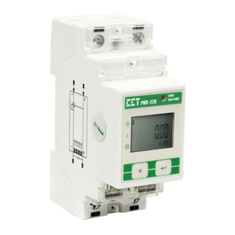
Revision Date: May 24, 2023
Mounting the Meter
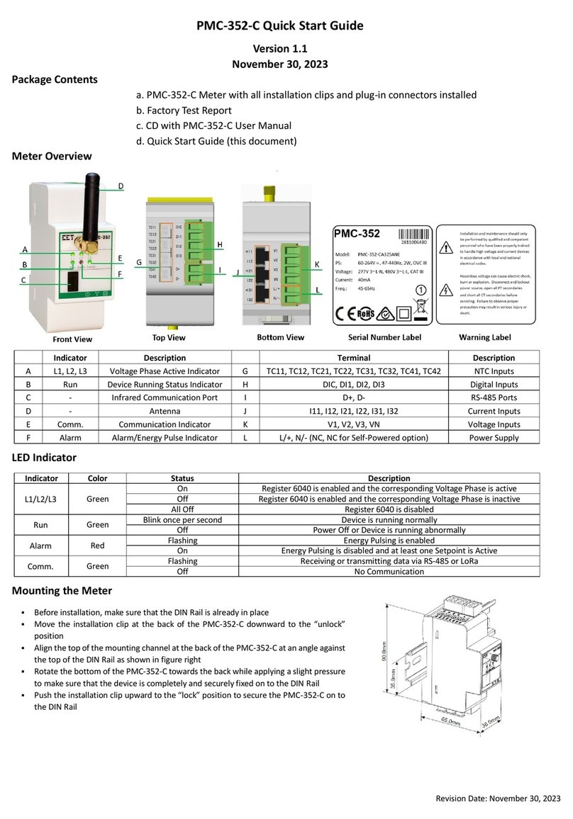
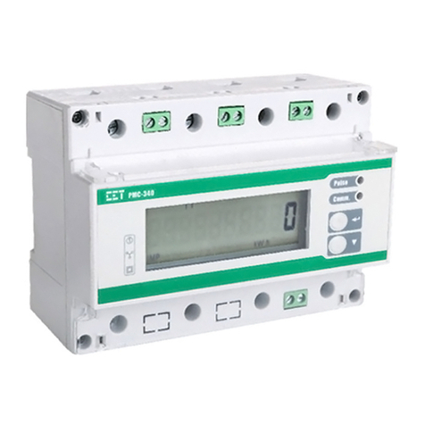
Pre-drill the mounting holes for the DIN rail and ensure it is already in place before installation.
Move the installation clips at the back of the device downward to the “unlock” position.
Align the top of the mounting channel at the back of the device at an angle against the top of the DIN rail as
shown in figure right.
Rotate the bottom of the device towards the back while applying a slight pressure to ensure that the device is
completely and securely fixed on to the DIN rail.
Push the installation clips upward to the “lock” position to secure the device on to the DIN rail.
4G Installation
Install the 4G antenna and position it in the correct location. Insert the SIM card into the slot in the direction shown in the following figure.
Using the Front Panel Buttons
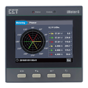
The Front Panel Display allows users to view the measurements and perform basic configuration. There are five main-menus, which are <Metering>,
<Power Quality>, <PQ Insight>, <Events>, and <Setup>. Each main menu includes multiple sub-menus for Measurements, Events or Setup Parameters.
The following table provides an overview of the Front Panel Buttons under different menus. The default password is 000001.
Metering / Power Quality / PQ Insight / Event Menu
<>
<>
<>
<>
The <> and <> are used for navigation between different menus on the Front Panel.
Before a sub-menu is selected,
•Press <> or <> to navigate the sub-menu list.
After a sub-menu is selected,
•Press <> or <> to display different pages of parameters.
•Use <> or <> to scroll to the next tab at the top pane.
•In the WFR and DWR page, press <> or <> to scroll backward or forward
through the waveform and <> or <> to zoom in/out of the waveform.
Before a parameter is selected,
•Use <>, <>, <> and <> buttons to
navigate around.
If a parameter is selected,
•For a numeric parameter, press <> or
<> to increment or decrement a numeric
value.
•For an enumerated parameter, press <>
or <> to scroll through the selection list.
<Enter>
•Press <Enter> to enter the selected Sub-menu
•In Max. & Min., press <Enter> to toggle between Max. and Min. measurements.
•In Harmonics, press <Enter> to switch between Harmonic Spectrum,
THD/TDD/CF/KF and Individual Harmonics.
•In Interharmonics, press <Enter> to switch between Interharmonic Spectrum,
TIHD and Individual Interharmonics.
•In PQ Insight, press <Enter> to Pause/Refresh the WF Capture, toggle the signal
selection for WF display, manually trigger WFR/DWR or view the latest event
Before a parameter is selected and modified,
•pressing <Enter > selects a parameter for
modification.
After a parameter is modified
•pressing <Enter > saves the present value of
the selected parameter into memory.
<Esc>
Press <Esc> to exit the current display.
•Press <Esc> to cancel the current change.
•Press <Esc> to exit a setup page, a pop-up
window will prompt to save the changes.
Basic Setup Parameters
Password Password Enter Password
The password digits cannot
be identical or sequential.
“000001”
The Wiring Connection of the meter
Basic > PT/CT
Ull Nominal Voltage on the Secondary Side
PT Nominal Primary Voltage
PT Nominal Secondary Voltage
CT Nominal Primary Current
CT Nominal Secondary Current
Comm. >
Ethernet (P1/P2)
Enable/Disable Ethernet P1 and select IP Addressing Mode
Ethernet Port 1 IP Address
Ethernet Port 1 Subnet Mask
Ethernet Port Gateway Address
Enable/Disable Ethernet P2 and select IP Addressing Mode
Ethernet Port 2 IP Address
Ethernet Port 2 Subnet Mask
Comm. >
RS-485 (P3)
Protocol RS-485 Port Protocol
Modbus, EtherGate,
Disable
Modbus
Baud Rate Data rate in bits per second
1200/2400/4800/
9600/19200/38400bps
9600


