manuals.online logo
Brands
  1. Home
  2. •
  3. Brands
  4. •
  5. CET
  6. •
  7. Measuring Instrument
  8. •
  9. CET PMC-S963-E User manual

CET PMC-S963-E User manual

Revision Date: July 26, 2023
PMC-S963-E Quick Start Guide
Version 1.0
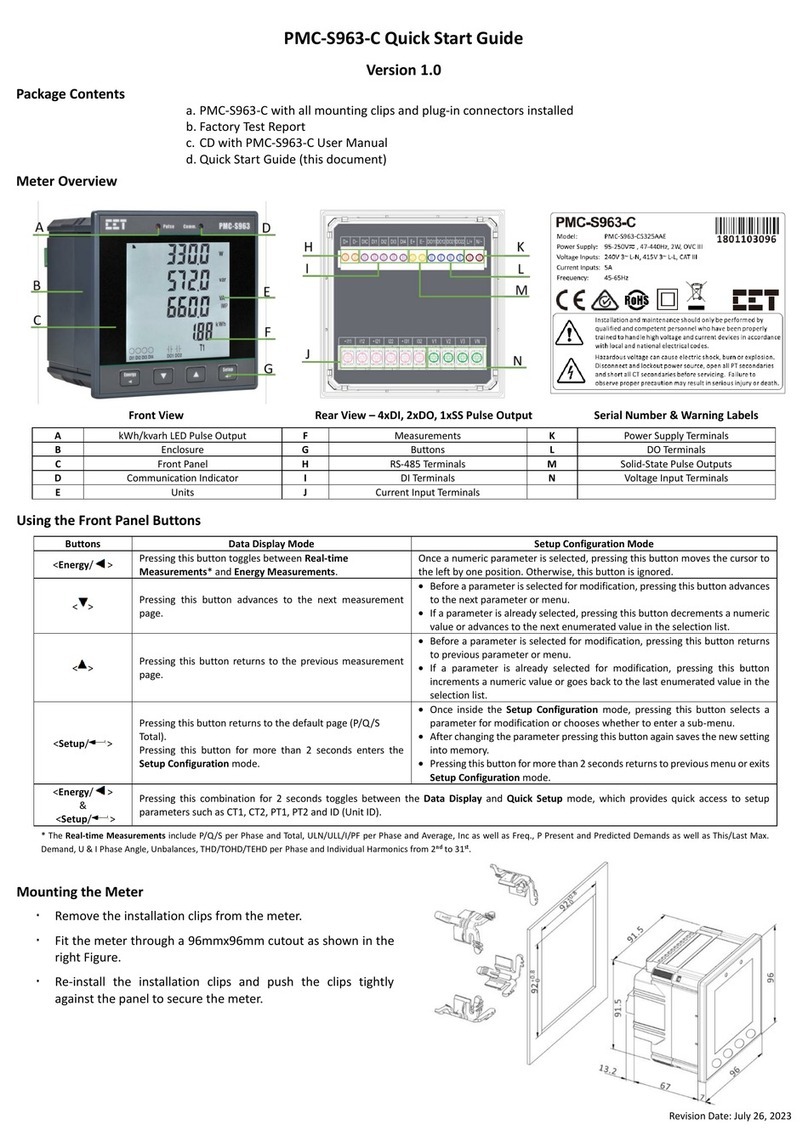
Package Contents a. PMC-S963-E with all mounting clips and plug-in connectors installed
b. Factory Test Report
c. CD with PMC-S963-E User Manual
d. Quick Start Guide (this document)
Meter Overview
Front View Rear View – 4xDI, 2xDO, 1xSS Pulse Output Serial Number & Warning Labels
A
kWh/kvarh LED Pulse Output
G
Buttons
M
Power Supply Terminals
B
Enclosure
H
RS-485 Terminals
N
DO Terminals
C
Front Panel
I
DI Terminals
O
Ethernet Port
D
Communication Indicator
J
Ung Input Terminals
P
Voltage Input Terminals
E
Units
K
Current Input Terminals
F
Measurements
L
Solid-State Pulse Outputs
Using the Front Panel Buttons
Buttons
Data Display Mode
Setup Configuration Mode
<Energy/ >
Pressing this button toggles between Real-time
Measurements* and Energy Measurements.
Once a numeric parameter is selected, pressing this button moves the cursor to
the left by one position. Otherwise, this button is ignored.
< >
Pressing this button advances to the next measurement
page.
•Before a parameter is selected for modification, pressing this button advances
to the next parameter or menu.
•If a parameter is already selected, pressing this button decrements a numeric
value or advances to the next enumerated value in the selection list.
< >
Pressing this button returns to the previous measurement
page.
•Before a parameter is selected for modification, pressing this button returns
to previous parameter or menu.
•If a parameter is already selected for modification, pressing this button
increments a numeric value or goes back to the last enumerated value in the
selection list.
<Setup/ >
Pressing this button returns to the default page (P/Q/S
Total).
Pressing this button for more than 2 seconds enters the
Setup Configuration mode.
•Once inside the Setup Configuration mode, pressing this button selects a
parameter for modification or chooses whether to enter a sub-menu.
•After changing the parameter pressing this button again saves the new setting
into memory.
•Pressing this button for more than 2 seconds returns to previous menu or exits
Setup Configuration mode.
<Energy/>
&
<Setup/ >
Pressing this combination for 2 seconds toggles between the Data Display and Quick Setup mode, which provides quick access to setup
parameters such as CT1, CT2, PT1, PT2, IP (Ethernet IP Address) and ID (Unit ID).
* The Real-time Measurements include P/Q/S per Phase and Total, ULN/ULL/I/PF per Phase and Average, Inc, Ung as well as Freq., P Present and Predicted Demands as well as This/Last Max.
Demand, U & I Phase Angle, Unbalances, THD/TOHD/TEHD per Phase and Individual Harmonics from 2nd to 31st.
Mounting the Meter
Remove the installation clips from the meter.
Fit the meter through a 96mmx96mm cutout as shown in the
right Figure.
Re-install the installation clips and push the clips tightly
against the panel to secure the meter.
Revision Date: July 26, 2023
Wiring Diagrams
Basic Setup Parameters
Menu
Parameters
Description
Options/Range
Default
Password Setup
/
Password
0000 to 9999
0
Basic Setup
WIRE TYPE
The Wiring Connection of the meter
DEMO/3P3W/3P4W
3P4W
CT 1*
Primary CT Ratio
1 to 30,000 (A)
5A
CT 2*
Secondary CT Ratio
1 to 5 (A)
5A
PT 1*
Primary PT Ratio
1 to 1,000,000 (V)
100V
PT 2*
Secondary PT Ratio
1 to 690 (V)
100V
PF
Set PF Convention
IEC/IEEE/-IEEE
IEC
kVA
Set kVA Calculation Method
Vector/Scalar
Vector
THD
Select between
% of Fundamental or % of RMS
THDF/THDR
THDF
PRD TIME
Set Demand Period
1 to 60 (min)
15
SUB NUM
Set No. of Sliding Windows
1 to 15
1
PRED RESP
Predicted Demand Response
70 to 99 (%)
70
LED PULSE
Enable LED kWh/kvarh Energy Pulsing
Disabled/kWh Tot./kvarh Tot/kWh
Imp./kWh Exp./kvarh Imp./kvarh Exp.
kWh Tot.
DO PULSE
Enable Solid-State Pulsing Output
kWh Tot.
SR TIME
Self-Read Time for both Max. Demand and
Max./Min. Log
0/--D--H
D: 1-28; H: 0-23
0
BLTO
Backlight Timeout
0 to 60 mins
5
I PHS A REV
Reverse Ia CT Polarity
Yes/No
No
I PHS B REV
Reverse Ib CT Polarity
Yes/No
No
I PHS C REV
Reverse Ic CT Polarity
Yes/No
No
Communication Setup
ID*
Set the Modbus Address
1 to 247
Last 2 digits of SN~
BD
Data rate in bits per second
1200/2400/4800/9600/19200/38400 bps
9600
CFG
Data Format
8N2/8O1/8E1/8N1/8O2/8E2
8E1
Ethernet Setup
IP*
Ethernet IP Address
/
192.168.0.100
SM
Ethernet Subnet Mask
/
255.255.255.0
GW
Ethernet Gateway
/
192.168.0.1
* These setup parameters are available in the Quick Setup mode.
~ If the last 2 digits of SN is 00, the default ID should be 100.

Other CET Measuring Instrument manuals

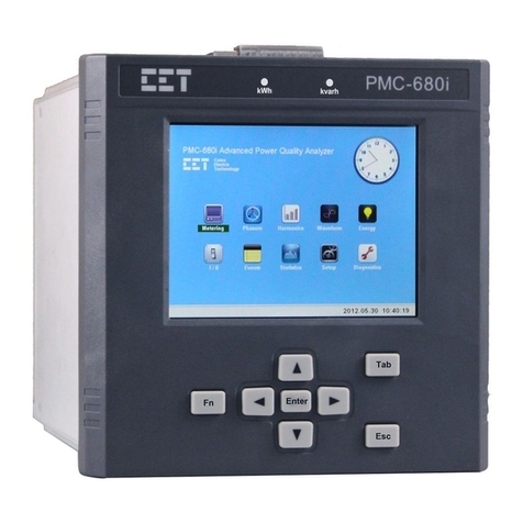
CET PMC-680i User manual

CET

CET PMC-680i User manual

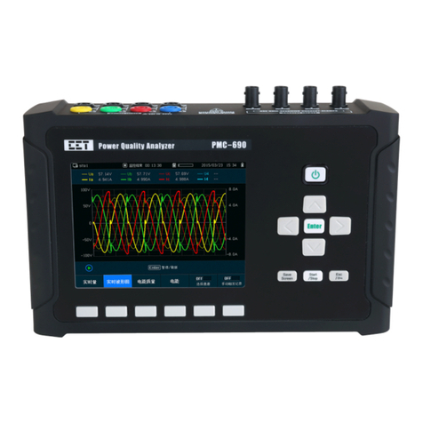
CET PMC-690 User manual

CET

CET PMC-690 User manual

CET PMC-S963-C User manual

CET

CET PMC-S963-C User manual

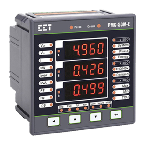
CET PMC-53M-E User manual

CET

CET PMC-53M-E User manual

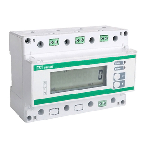
CET PMC-340 User manual

CET

CET PMC-340 User manual

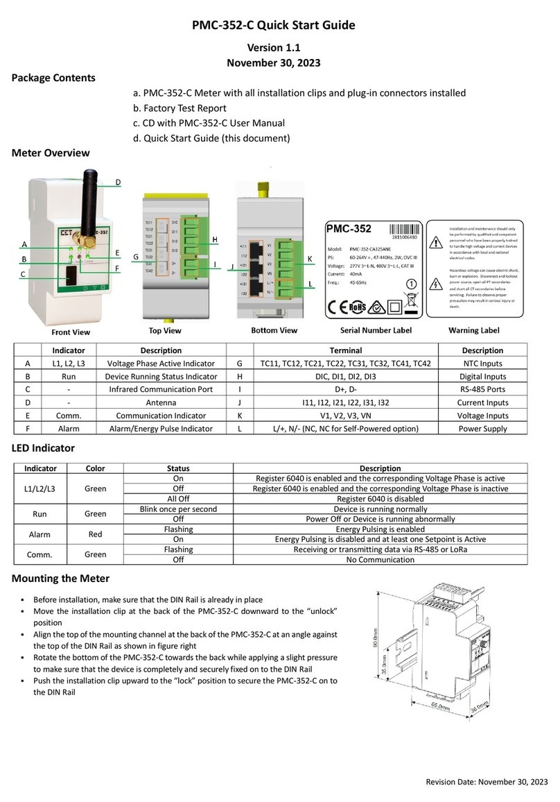
CET PMC-352-C User manual

CET

CET PMC-352-C User manual

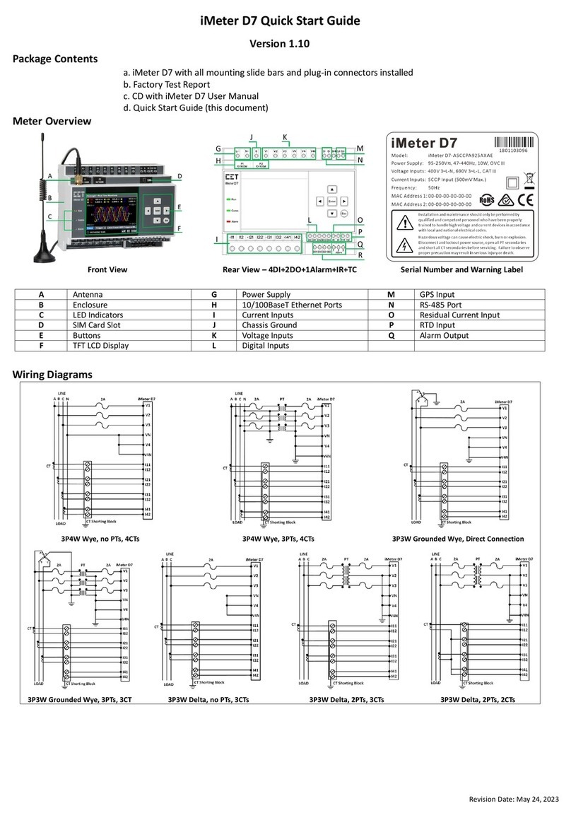
CET iMeter D7 User manual

CET

CET iMeter D7 User manual

CET PMC-352 User manual

CET

CET PMC-352 User manual

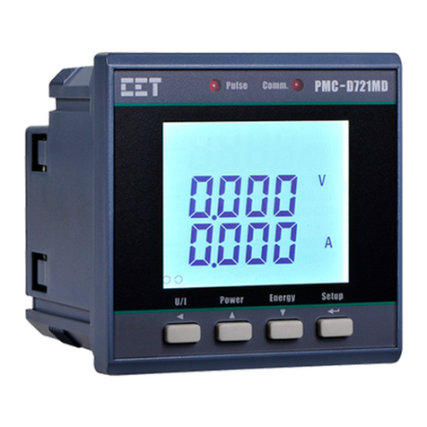
CET PMC-D721MD User manual

CET

CET PMC-D721MD User manual

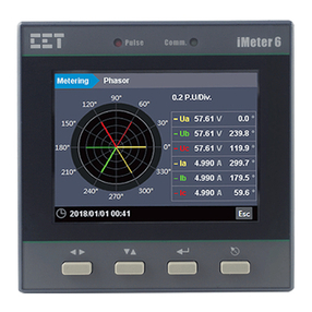
CET iMeter 6 User manual

CET

CET iMeter 6 User manual

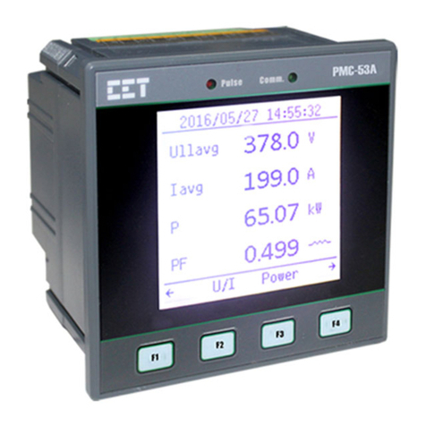
CET PMC-53A User manual

CET

CET PMC-53A User manual

CET PMC-512-A User manual

CET

CET PMC-512-A User manual

CET PMC-220 User manual

CET

CET PMC-220 User manual

CET PMC-630 Series User manual

CET

CET PMC-630 Series User manual

CET PMC-352 User manual

CET

CET PMC-352 User manual

CET PMC-680i User manual

CET

CET PMC-680i User manual

CET PMC-220 User manual

CET

CET PMC-220 User manual

CET PMC-53M-E User manual

CET

CET PMC-53M-E User manual

CET PMC-53A User manual

CET

CET PMC-53A User manual

CET PMC-340 User manual

CET

CET PMC-340 User manual

CET PMC-53M-A User manual

CET

CET PMC-53M-A User manual

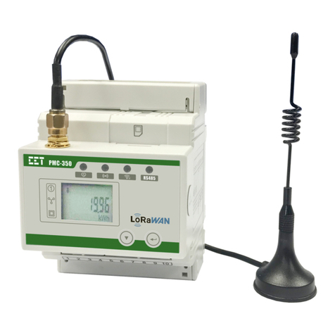
CET PMC-350 User manual

CET

CET PMC-350 User manual

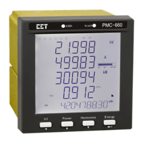
CET PMC-660 Series User manual

CET

CET PMC-660 Series User manual

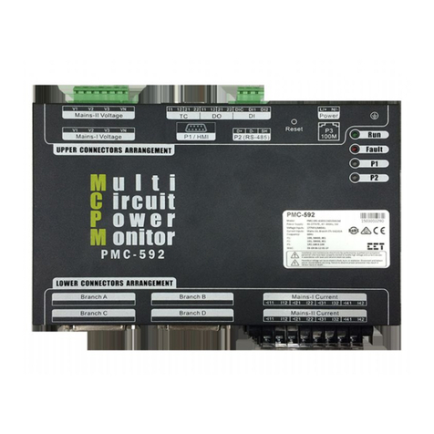
CET PMC-592 User manual

CET

CET PMC-592 User manual

Popular Measuring Instrument manuals by other brands

OHAUS Defender I-D33P15B1R1 instruction manual

OHAUS

OHAUS Defender I-D33P15B1R1 instruction manual

AEMC instruments CA846 user manual

AEMC instruments

AEMC instruments CA846 user manual

Gryzzly H3022 owner's manual

Gryzzly

Gryzzly H3022 owner's manual

BRUEL & KJAER VIBROCONTROL 920 user manual

BRUEL & KJAER

BRUEL & KJAER VIBROCONTROL 920 user manual

Crosby SP Handheld Plus SW-HHP user manual

Crosby

Crosby SP Handheld Plus SW-HHP user manual

Farnell Sound level meter instruction manual

Farnell

Farnell Sound level meter instruction manual

Extech Instruments 475055 user manual

Extech Instruments

Extech Instruments 475055 user manual

SUTO S551 Instruction and operation manual

SUTO

SUTO S551 Instruction and operation manual

R&S NRT2 user manual

R&S

R&S NRT2 user manual

PCE Instruments PCE-T 260 Operation manual

PCE Instruments

PCE Instruments PCE-T 260 Operation manual

Kimo DB 200 user manual

Kimo

Kimo DB 200 user manual

Datacolor SpyderTV quick start guide

Datacolor

Datacolor SpyderTV quick start guide

Macherey-Nagel NANOCOLOR Advance Operating	 instruction

Macherey-Nagel

Macherey-Nagel NANOCOLOR Advance Operating instruction

Sokkia iM-100 Series Quick manual

Sokkia

Sokkia iM-100 Series Quick manual

Veris H704-42 installation guide

Veris

Veris H704-42 installation guide

Hanna Instruments HI762 instruction manual

Hanna Instruments

Hanna Instruments HI762 instruction manual

TempSen ITAG 3 Series quick guide

TempSen

TempSen ITAG 3 Series quick guide

OfiTE 800 instruction manual

OfiTE

OfiTE 800 instruction manual

manuals.online logo
manuals.online logoBrands
  • About & Mission
  • Contact us
  • Privacy Policy
  • Terms and Conditions

Copyright 2025 Manuals.Online. All Rights Reserved.