CG Emotron CDN Series User manual

Emotron CDN
Motor mounted AC drive
0.75 ... 7.5 kW
Hardware manual


Contents
i
1
Aboutthisdocumentation
1.1
Validity information
. . . . . . . . . . . . . . . . . . . . . . . . . . . . . . . . . . . . . . . . . . . . . . . . . . 1
. . . . . . . . . . . . . . . . . . . . . . . . . . . . . . . . . . . . . . . . . . . . . . . . . . 1
1.2
Document history
1.3
Conventions used
. . . . . . . . . . . . . . . . . . . . . . . . . . . . . . . . . . . . . . . . . . . . . . . . . . . . 2
. . . . . . . . . . . . . . . . . . . . . . . . . . . . . . . . . . . . . . . . . . . . . . . . . . . . 2
1.4 Terms and abbreviations used . . . . . . . . . . . . . . . . . . . . . . . . . . . . . . . . . . . . . . . . . . 3
1.5
Notes used
. . . . . . . . . . . . . . . . . . . . . . . . . . . . . . . . . . . . . . . . . . . . . . . . . . . . . . . . . . 4
2 Safety instructions . . . . . . . . . . . . . . . . . . . . . . . . . . . . . . . . . . . . . . . . . . . . . . . . . . . . . . . . . 5
2.1
General safety and application notes for Emotron CDN AC
drives
. . . . . . . . . . . . . . . . . 5
2.2
Residual hazards
. . . . . . . . . . . . . . . . . . . . . . . . . . . . . . . . . . . . . . . . . . . . . . . . . . . . . 8
3
Product description
. . . . . . . . . . . . . . . . . . . . . . . . . . . . . . . . . . . . . . . . . . . . . . . . . . . . . . . . 9
3.1
System overview
3.2
Device features
. . . . . . . . . . . . . . . . . . . . . . . . . . . . . . . . . . . . . . . . . . . . . . . . . . . . . 9
. . . . . . . . . . . . . . . . . . . . . . . . . . . . . . . . . . . . . . . . . . . . . . . . . . . . . . 10
3.3
Identification
. . . . . . . . . . . . . . . . . . . . . . . . . . . . . . . . . . . . . . . . . . . . . . . . . . . . . . . . 11
3.4 Product key . . . . . . . . . . . . . . . . . . . . . . . . . . . . . . . . . . . . . . . . . . . . . . . . . . . . . . . . . . 12
3.4.1
Wiring Unit
. . . . . . . . . . . . . . . . . . . . . . . . . . . . . . . . . . . . . . . . . . . . . . . . . . 12
3.4.2
CommunicationUnit
. . . . . . . . . . . . . . . . . . . . . . . . . . . . . . . . . . . . . . . . . . 13
3.4.3
Drive Unit
. . . . . . . . . . . . . . . . . . . . . . . . . . . . . . . . . . . . . . . . . . . . . . . . . . . 13
3.5 Overview of control terminals
. . . . . . . . . . . . . . . . . . . . . . . . . . . . . . . . . . . . . . . . . . 14
4
Technicaldata
. . . . . . . . . . . . . . . . . . . . . . . . . . . . . . . . . . . . . . . . . . . . . . . . . . . . . . . . . . . . 15
4.1
Generaldataandoperating conditions
. . . . . . . . . . . . . . . . . . . . . . . . . . . . . . . . . 15
4.2
Rated data
. . . . . . . . . . . . . . . . . . . . . . . . . . . . . . . . . . . . . . . . . . . . . . . . . . . . . . . . . . 20
4.2.1
Operation with normal duty on 400 V
system . . . . . . . . . . . . . . . . . . . . . . 20
4.2.2
Operation with normal duty on 480 V system
. . . . . . . . . . . . . . . . . . . . . 22
4.2.3
Operation with heavy duty operation . . . . . . . . . . . . . . . . . . . . . . . . . . . . . 24
4.2.4
Operation with rated mains voltage 400 V
– Heavy duty. . . . . . . . . . . . 26
4.2.5
Operation with rated mains voltage 480 V –Heavy duty
. . . . . . . . . . 28
4.3
Overcurrent operation
. . . . . . . . . . . . . . . . . . . . . . . . . . . . . . . . . . . . . . . . . . . . . . . . 30
4.4
Switching frequency reduction
. . . . . . . . . . . . . . . . . . . . . . . . . . . . . . . . . . . . . . . . . 32

i
Contents
4.5 Power terminals . . . . . . . . . . . . . . . . . . . . . . . . . . . . . . . . . . . . . . . . . . . . . . . . . . . . . . 33
4.5.1 Emotron CDN40-2P2 – 40-8P7 ( 0.75 ... 3 kW) . . . . . . . . . . . . . . . . . . . . . . . 33
4.5.2
Emotron CDN40-012 – 40-016 ( 4 ... 7.5 kW
) . . . . . . . . . . . . . . . . 35
4.6 Control terminals . . . . . . . . . . . . . . . . . . . . . . . . . . . . . . . . . . . . . . . . . . . . . . . . . . . . . 37
4.6.1 Overview . . . . . . . . . . . . . . . . . . . . . . . . . . . . . . . . . . . . . . . . . . . . . . . . . . . . 37
4.6.2.
General data
. . . . . . . . . . . . . . . . . . . . . . . . . . . . . . . . . . . . . . . . . . . . . . . . 38
4.6.3 CANopen® . . . . . . . . . . . . . . . . . . . . . . . . . . . . . . . . . . . . . . . . . . . . . . . . . . . 39
4.7 Dimensions . . . . . . . . . . . . . . . . . . . . . . . . . . . . . . . . . . . . . . . . . . . . . . . . . . . . . . . . . . 40
4.7.1
Standardmotormounting
. . . . . . . . . . . . . . . . . . . . . . . . . . . . . . . . . . . . . 40
5 Installation
. . . . . . . . . . . . . . . . . . . . . . . . . . . . . . . . . . . . . . . . . . . . . . . . . . . . . . . . . . . . . . . 41
5.1 Important notes . . . . . . . . . . . . . . . . . . . . . . . . . . . . . . . . . . . . . . . . . . . . . . . . . . . . . . 41
5.2
Safety instructions for the installation according to UL/CSA
. . . . . . . . . . . . . . . . . 44
5.3
Installation according to EMC (installation of a CE−typical drive system) . . . . . . . 46
5.3.1
Shielding
. . . . . . . . . . . . . . . . . . . . . . . . . . . . . . . . . . . . . . . . . . . . . . . . . . . . 46
5.3.2 Motor cable . . . . . . . . . . . . . . . . . . . . . . . . . . . . . . . . . . . . . . . . . . . . . . . . . . 47
5.3.3 Control cables . . . . . . . . . . . . . . . . . . . . . . . . . . . . . . . . . . . . . . . . . . . . . . . . 48
5.3.4
Detecting and eliminating EMC interferences
5.4
Measures when drive is used in IT systems . . . . . . . . . . . . . . . . . . . . . . . . . . . .
48
5.5
Power terminals . . . . . . . . . . . . . . . . . . . . . . . . . . . . . . . . . . . . . . . . . . . . . . . . . . . . . . 50
5.5.1
StandardI/O
. . . . . . . . . . . . . . . . . . . . . . . . . . . . . . . . . . . . . . . . . . . . . . . . . 51
5.5.2 Extended I/O . . . . . . . . . . . . . . . . . . . . . . . . . . . . . . . . . . . . . . . . . . . . . . . . . 52
5.5.3 CANopen® . . . . . . . . . . . . . . . . . . . . . . . . . . . . . . . . . . . . . . . . . . . . . . . . . . .
53
6 Commissioning
. . . . . . . . . . . . . . . . . . . . . . . . . . . . . . . . . . . . . . . . . . . . . . . . . . . . . . . . . . .
54
6.1 Before you start
. . . . . . . . . . . . . . . . . . . . . . . . . . . . . . . . . . . . . . . . . . . . . . . . . . . . . .
54
6.2 Handling the memory module . . . . . . . . . . . . . . . . . . . . . . . . . . . . . . . . . . . . . . . . . .
56
6.3
Setting
elements . . . . . . . . . . . . . . . . . . . . . . . . . . . .
58
6.3.1
Before switching on
. . . . . . . . . . . . . . . . . . . . . . . . . . . . . . . . . . . . . . . . . . .
61
6.3.4 Commissioning steps . . . . . . . . . . . . . . . . . . . . . . . . . . . . . . . . . . . . . . . . . .
62
6.4 Diagnostics . . . . . . . . . . . . . . . . . . . . . . . . . . . . . . . . . . . . . . . . . . . . . . . . . . .. . . .
63
7 Braking operation
. . . . . . . . . . . . . . . .
. . . . . . . . . . . . . . . . . . . . . . . . . . . . . . . . . . . . . . . . . . . . . .
64
8
Accessories (overview)
. . . . . . . . . . . . . . . . . . . . . . . . . . . . . . . . . . . . . . . . . . . . . . . . . . . . .
65
8.1
Memory module
. . . . . . . . . . . . . . . . . . . . . . . . . . . . . . . . . . . . . . . . . . . . .
65

About
this
documentation
Validity
information
1
CG Drives & Automation 1
1
About this documentation
1.1
Validity information
Contents
This Hardware Manual informs you how to use the Emotron CDNseries as directed.
Validity
Type
Typedesignation
Emotron CDN
CDN40-2P2-65
Target group
This Hardware Manual is intended for all persons who design, install, commission, and
adjust Emotron CDN drives range.
Tip!
Information and tools concerning the CG products can be found in thedownload
area at
www.emotron.com

1
About
this
documentation
Document
history
2 CG Drives & Automation
1.2
Document history
Material number
Version
Description
01-6460-01
R0
2017-01-27
First edition
1.3
Conventions used
This documentation uses the following conventions to distinguish between different
typesofinformation:
Spelling ofnumbers
Decimal separator
Point
In general, the decimal point is used.
For instance: 1234.56
Warnings
UL warnings
Given in English and French
UR warnings
Text
Program name
» «
PC software
For example:
»
Easy starter
«
Icons
Page reference
Referencetoanother page withadditional
information
For instance:
16 = see page 16
Documentation reference
Reference to another documentation with
additional information
For example:
01-xxxx-yy = see
d
ocumentation 01-xxxx-yy

About
this
documentation
Validity
information
1
CG Drives & Automation 3
1.4
Terms and abbreviations used
Term Meaning
Device size Used as generic term for a group of devices which have the same dimensions
(depth, height and width) but different power ratings.
Standard device Used as generic term when actions and features are described which are very
similar or the same for different versions or device sizes, e.g.
•
mechanical installation or
•
power terminals
DU
Drive unit
CDN controller
CU
Communication unit
Optional interfaces per I/O, fieldbus
WU
Wiring unit
Ready−made motor connection, replaces the motor terminal box
Abbreviation
Meaning
Cat. Category according to EN 954−1 (valid until 30 November 2009)
Opto supply Optocoupler supply for controlling the drivers
PELV
Protective Extra Low Voltage
PWM
Pulse Width Modulation
n. c. Terminal not assigned

1
About
this
documentation
Document
history
4 CG Drives & Automation
1.5
Notes used
The following pictographs and signal words are used in this documentation to indicate
dangers andimportant information:
Safety instructions
Structureofsafety instructions:
Meaning
Danger!
Danger of personal injury through dangerous electrical voltage.
Reference to an imminent danger that may result in death or
serious personal injury if the corresponding measures are not
taken.
Danger!
Danger of personal injury through a general source of danger.
Reference to an imminent danger that may result in death or
serious personal injury if the corresponding measures are not
taken.
Stop!
Danger of property damage.
Reference to a possible danger that may result in property
damage if the corresponding measures are not taken.
Application notes
Pictograph and signal word
Meaning
Note!
Important note to ensure troublefree operation
Tip!
Useful tip for simple h
Reference to another documentation
Special safety instructions and application notes
Pictograph and signal word
Meaning
Warnings!
Safety note or application note for the operation according to
UL or CSA requirements.
The measures are required to meet the requirements according
to UL or CSA.
Warnings!
Danger!
(characterises
the
type
and
severity
of
danger)
Note
(describes
the
danger
and
gives
information
about
how
to
prevent
dangerous
situations)

Safety
instructions
General
safety
and
application
notes
2
CG Drives & Automation 5
2
Safety instructions
2.1
General safety and application notes for Emotron CDN drives
(in accordance with Low−Voltage Directive 2014/35/EU)
For your personal safety
Disregarding the following safety measures can lead to severe injury to persons and
damage to material assets:
Onlyusetheproductasdirected.
Nevercommissiontheproductintheeventofvisibledamage.
Never commission the product before assembly has been completed.
Donotcarryoutanytechnicalchangesontheproduct.
Onlyusetheaccessoriesapprovedfortheproduct.
OnlyuseoriginalsparepartsfromCG.
Observeallregulationsforthepreventionofaccidents,directivesandlaws
applicable on site.
Transport, installation, commissioning and maintenance work must only be carried
outbyqualifiedpersonnel.
–
Observe IEC 364 and CENELEC HD 384 or DIN VDE 0100 and IEC report 664 or
DIN VDE 0110 and all national regulations for the prevention of accidents.
–
According to this basic safety information, qualified, skilled personnel are persons
who are familiar with the assembly, installation, commissioning, and operation of
the product and who have the qualifications necessary for their occupation.
Observeallspecificationsinthisdocumentation.
–
This is the condition for safe and trouble−free operation and the achievement of
the specified product features.
–
The procedural notes and circuit details described in this documentation are only
proposals. It’s up to the user to check whether they can be transferred to the
particular applications. CG does not accept any liability for the suitability of the
procedures and circuit proposals described.
Depending on their degree of protection, some parts of the Emotron CDN drives
and their accessory
components can be live during operation. Surfaces can be hot.
–
Non−authorised removal of the required cover, inappropriate use, incorrect
installation or operation, creates the risk of severe injury to persons or damage to
material assets.
–
For more information, please see thedocumentation.
Highamountsofenergyareproducedinthedrive.Thereforeitisrequiredto
wear
personal protective equipment (body protection, headgear, eye protection, ear
protection, hand guard).

2
Safety
instructions
General
safety
and
application
notes
6 CG Drives & Automation
Application as directed
AC drives are components which are designed for installation in electrical systems or
machines. They are not to be used as domestic appliances, but only for industrial purposes
according to EN 61000−3−2.
When AC drives are installed into machines, commissioning (i.e. starting of the operation
as directed) is prohibited untilitisproven thatthe machine complies with the regulations
of the EC Directive 2006/42/EC (Machinery Directive); EN 60204 must be observed.
Commissioning (i.e. starting of the operation as directed) is only allowed when there is
compliance with the EMC Directive (2004/108/EC).
The AC drives meet the requirements of the Low−Voltage Directive 2006/95/EC. The
harmonised standard EN 61800−5−1 applies to the AC drives.
The technical data and supply conditions can be obtained from the nameplate and the
documentation. They must be strictly observed.
Warning:
AC drives are products which can be installed in drive systems of category C2
according to EN 61800−3. These products can cause radio interferences in residential areas.
In this case, special measures can be necessary.
Transport, storage
Please observe the notes on transport, storage, and appropriate handling.
Observe the climatic conditions according to the technical data.
Installation
The AC drives must be installed and cooled according to the instructions given in the
corresponding documentation.
The ambient air must not exceed degree of pollution 2 according to EN 61800−5−1.
Ensure proper handling and avoid excessive mechanical stress. Do not bend any
components and do not change any insulation distances during transport or handling. Do
not touch any electronic components and contacts.
AC drives contain electrostatic sensitive devices which can easily be damaged by
inappropriate handling. Do not damage or destroy any electrical components since this
might endanger your health!
Electrical connection
When working on live AC drives, observe the applicable national regulations for the
prevention of accidents.
The electrical installation must be carried out according to the appropriate regulations
(e.g. cable cross−sections, fuses, PE connection). Additional information can be obtained
from the documentation.
The documentation provides notes on EMC−compliant installation (shielding, earthing,
filter arrangement, and laying of cables). Please also observe these notes when installing
CE−labelled AC drives. The manufacturer of the machine or plant is responsible for the
compliance with the required limit values associated with EMC legislation.
Emotron CDN drives may cause a DC current in the PE conductor. If a residual current
device is used as a protective means in the case of direct or indirect contact with a
three−phase controller, a residual current device of type B must be used on the current
supply side of thecontroller. If the controller has a single−phase supply, it is also permissible
to use a residualcurrent device of type A. Apart from the use of a residual current device,
other protective measures can also be taken, such as isolation from the environment by
double or reinforced insulation, or separation from the supply system by means of a
transformer.

Safety
instructions
General
safety
and
application
notes
2
CG Drives & Automation 7
Operation
If necessary, systems including AC drives must be equipped with additional monitoring
and protection devices according to the valid safety regulations (e.g. law on technical
equipment, regulations for the prevention of accidents). The AC drives can be adapted to
your application. Please observe the corresponding information given in the
documentation.
After the controller has been disconnected from the supply voltage, all live components
and power terminals must not be touched immediately because capacitors can still be
charged. Please observe the corresponding stickers on the controller.
All protection covers and doors must be shut during operation.
Notes for UL−approved systems with integrated AC drives: UL warnings are notes that
only apply to UL systems. The documentation contains special UL notes.
Maintenanceandservicing
The AC drives do not require any maintenance if the prescribed operating conditions are
observed.
Disposal
Recycle metal and plastic materials. Ensure professional disposal of assembled PCBs.
The product−specific safety and application notes given in these instructions must
beobserved!

2
Safety
instructions
Residual
hazards
8 CG Drives & Automation
2.2
Residual hazards
Protection of persons
Switchoffmainsvoltagebeforeremovingthecontroller(DriveUnit).
Beforeworkingonthecontroller,checkifnovoltageisappliedtothepower
terminals because
–
depending on the device
−
the power terminals U, V, W, Rb1, Rb2, T1 and T2 remain
live for at least 3 minutes after disconnecting the mains.
–
the power terminals L1, L2, L3; U, V, W, Rb1, Rb2, T1 and T2 remain live when the
motor is stopped.
Device protection
Only connect/disconnect all pluggable terminals in deenergised condition!
Onlydisconnecttheinvertersfromtheinstallation,e.g.fromthemotoror
mounting
wall, in deenergised condition!
Motor protection
Withsomesettingsofthecontroller,theconnectedmotorcanbeoverheated.
–
E.g. longer operation of the DC injectionbrake.
–
Longer operation of self−ventilated motors at low speed.
–
Wrong frequency or voltage settings in the motor parameters (especially with
120 Hz motors).
Protection of the machine/system
Drivescanreachdangerousoverspeeds(e.g.settingofhighoutputfrequenciesin
connection with motors and machines unsuitable for such conditions):
–
The AC drives do not offer any protection against such operating conditions. Use
additional components for this purpose.
Warning by symbols
Icon
Description
Long discharge time:
All power terminals remain live for up to 3 minutes after mains disconnection!
High leakagecurrent:
Carry out fixed installation and PE connection in accordance with EN 61800−5−1!
Electrostatic sensitive devices:
Before working on the device, the staff must ensure to be free of electrostatic charge!
Hotsurface:
Use personal protective equipment or wait until devices have cooled down!
Product
description
System
overview
3
CG Drives & Automation 9
3
Product description
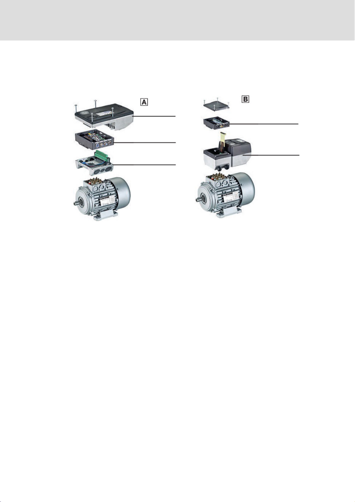
3.1
System overview
Emotron CDN40 0.75 ... 4.0 kW
Emotron CDN40 5.5 ... 7.5 kW
Drive unit
Communication unit
Wiring unit
Communication unit
Drive unit
Wiring unit

3
Product
description
10 CG Drives & Automation
Device features
3.2
Device features
General features
Functional features
Compactmotorinverter
Modulardesign
Scalable fieldbus communication (optional)
On site diagnostics per status LEDs
I/O accessories (optional)
Pluggable memory module
Features
Version
Power
range
0.75
...
7.5
kW
Fieldbus
communication
(optional)
–
CANopen
Integrated
interference
suppression
according
to
EN
61800−3
Flying
restart
circuit
Operating
modes
–
VFCplus:
V/f
open
loop
control,
linear
and
quadratic
–
SLVC:
sensorless
vector
control
(torque/speed)
–
VFC
eco
(energy−saving
function)
S−shaped
ramps
for
almost
jerk−free
acceleration
and
deceleration
Fixed
frequencies
3
Overload
current
200
%
(3
s)
IT
system
usability
Incremental
encoder
evaluation
Two−track,
10
kHz
Outputs
Optional:
1
digital
output
1
potential−free
relay
contact,
2
A,
NO
contact
DC−injection
braking
Mounting
Motor
mounting

Product
description
3
CG Drives & Automation 11
Identification
3.3
Identification
Due to the modular design of the Emotron CDN AC drives, every unit has an own
nameplate.
The nameplate shows the type designation of the respective unit. The type designation
serves to exactly identify a unit.
Note
Via the type designation, detailed device properties can be identified using the following
type code. The list containing the type code, features, and device properties does not take
any restrictions with regard to possible combinations into consideration.
Type designation

3
Product
description
Product
key
12 CG Drives & Automation
3.4
Product key
Due to the modular structure of the Emotron CDN AC drive, every unit needs an own
part number. Although a part number is also defined for the Emotron CDN AC drive as a
set, for practical and logistical reasons it cannot be fixed visibly on the set or on the
individual units.
The following lists inform you about the part number for:
Wiring Unit
Wiring level to the motor and mains connection
CommunicationUnit
Connectionlevelforfieldbuscommunicationandfurtherinputsandoutputs,partially
optional
Drive Unit
Emotron CDN AC drive
Accessories
Efficiency−enhancing and cost−cutting
3.4.1
Wiring Unit
Module
part
Wiring
Unit
–
Emotron CDN
Type
P/n
Motor size
Used with Drive unit
CDN-WU-Size 1
01-6360-01
1
=
63
/
71
Frame size 1
CDN-WU-Size 2
01-6360-02
2
=
80
/
090
/
100
Frame size 1
CDN-WU-Size 3
01-6360-03
3
=
80
/
90
/
100
/
112
Frame size 2
CDN-WU-Size 4
01-6360-04
4
=
80
/
90
/
100
/
112
Frame size 3
CDN-WU-Size 5
01-6360-05
5
=
132
Frame size 3
Enclosure
IP66

Product
description
Communication Unit
3
CG Drives & Automation 13
3.4.2
Communication Unit
Module
part
Communication
Unit
–
Emotron CDN
Type
P/n
Description
CDN-COM-Std IO
01-6361-00
Standard I/O
CDN-COM-Ext IO
01-6361-01
Extended I/O
CDN-COM-CANbus
01-6361-02
CANopen + Standard I/O
Connection
system
I/O
modules/fieldbus
S
tandard
I/O,
extended
I/O:
terminal
Type
of
protection
IP65
3.4.3
Drive Unit
Module
part
Drive
Unit
–
Emotron CDN
Type
P/n
Rated output current, Normal duty (120%)
Drive unit
frame size
In @ 400V
(A)
In @ 480V
(A)
CDN40-2P2-65
CDN402P2
2.2
2.1
1
CDN40-3P8-65
CDN403P8
3.8
3.7
1
CDN40-4P8-65
CDN404P8
4.8
4.5
1
CDN40-7P0-65
CDN407P0
7.0
5.6
2
CDN40-8P7-65
CDN408P7
8.7
7.3
2
CDN40-012-65
CDN40012
11.6
9.5
3
CDN40-016-65
CDN40016
15.6
13.0
3
Current
e.g.
012
=
12 Amp
Voltage
class
40
=
400/480
V,
3/PE
AC
(also
for
IT
systems)
Type
of
protection
IP65

3
Product
description
14 CG Drives & Automation
3.5
Overview of control terminals
The control terminals of the Emotron CDN AC drives are always located in the
Communication Unit.
The type of fieldbus version, power class of the inverter, or motor frame size have no
influence on the availability of the device versions.
For Emotron CDN AC drive without a fieldbus link, two types of control terminals are
available:
StandardI/O
ExtendedI/O
For Emotron CDN AC drive with fieldbus link, two types of control terminals are
available:
With the I/O functions as for the standard I/O, but without an
analog input and
relay output
Connection options for Communication Unit
Plugs
Type
X4
Digital input/output
Analog
input
AI/AU
Relay
COM/NO
Part no
RFR
(Enable)
DIx
DO1
01-6361-00
Standard I/O
1)
1 x
5 x
01-6361-01
Extended I/O
1)
1 x
8 x
2 x
01-6361-02
CANopen
1 x
5 x
−
−
✓
Available
−
Not available
1)
Without a fieldbus link

Technical
data
General
data
and
operating
conditions
4
CG Drives & Automation 15
4
Technical data
4.1
General data and operating conditions
Conformity and approval
Conformity
CE
2006/95/EC
LowVoltage Directive
EAC
(TR CU 004/2011)
On safety of low voltage
equipment
Eurasian Conformity
TR CU: Technical
Regulation ofCustoms
EAC
(TR CU 020/2011)
Electromagnetic
compatibility of
technical
means
Eurasian Conformity
TR CU: Technical
Regulation ofCustoms
Approval
UR
UL 508C
Power Conversion
Equipment, File No.
E254612
C
UR
C22.2 No 274−13
Protection of persons and equipment
Enclosure
•
Close unused bores for cable glands with blanking
plugs!
•
Close unused connectors with protection
EN 60529
Emotron CDN set:
IP65
NEMA 250
Emotron CDN set:
Type 4
Field Package
without switch
0.75 ... 4.0 kW
5.5 ... 7.5 kW
Type 1
Type 4X (interior)
(Earth) leakage current
EN 61800−5−1
> 3.5 mA AC, > 10 mA DC
Observe the
regulations andsafety
i i!
Total fault current
In TN systems the following earth−leakage circuit
breakers canbe used:
Motor mounting
0.75 ... 4.0 kW
30 mA, type B
5.5 ... 7.5 kW
30 mA, type B
5.5 ... 7.5 kW
300 mA, type B

4
Technical
data
s
16 CG Drives & Automation
Protection of persons and equipment
Additional
equipotential
bonding
M5 thread with terminal in the WU for connection of a
16mm PE cable
Protective insulation of
control circuits
EN 61800−5−1
Safe isolation from mains by double (reinforced) insulation
Insulation resistance
EN 61800−5−1
Site altitude
0 ... 2000 m
Overvoltage category III
2000 ... 4000 m
Overvoltage category II
Short−circuit strength
EN 61800−5−1
Connection:
Motor
To a limited extent, the
controller is inhibited, error
acknowledgement required
Motor holding brake, brake
resistor
No
PTC, control terminals
Full
Earth−fault strength
EN 61800−5−1
Connection:
Motor (at controller
enable)
To a limited extent, the
controller is inhibited, error
acknowledgement required
Motor (during operation)
No
Brake resistor, PTC
No
Protective measures
against
•
Short circuit on the motor side at switch−on and during
operation
•
Motor stalling
•
Motor overtemperature
–
Input for PTC or thermal contact
–
I
2
t monitoring
Cyclic mainsswitching
•
Switchings/minute
3
•
Switchings/hour
Max. 20
•
Switching pause
After switching the mains3
times in one minute, there must
be a switching pause of
9 minutes.
Starting current
2 x I
N
Supply conditions
Mains connection
Power system
Motor connection
Motors
EN 60034
Only use motors suitable for inverter operation. Insulation
resistance:
at least û 1.5 kV, at least du/dt 5 kV/ s
Length of the motor
cable
< 20 m (Shielded cable)
TT,
TN
(with
an
earthed
neutral)
Operation
permitted
without
restrictions.
IT
Implement
the
measure
described
for
IT
systems
(remove
IT
screw).
The
machine/system
manufacturer
is
responsible
for
compliance
with
EMC
requirements
for
noise
emission
(EN
61800−3)
for
the
machine/plant!
Operation
with
an
integrated
safety
system
is
not
permissible.
This manual suits for next models
7
Table of contents
Other CG Controllers manuals


