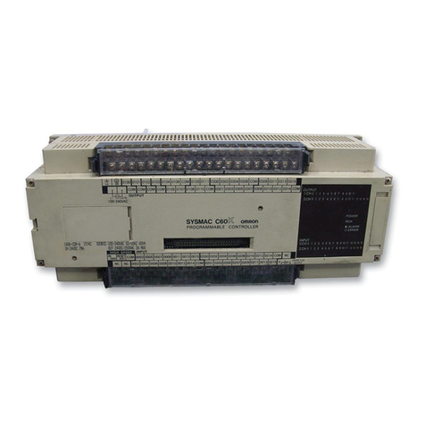
Omron SYSMAC C500 User manual

Cat. No. W132-E1-4
Programmable Controller
SYSMAC
C500

C500 Programmable Controller
Installation Guide
Revised May 2000

!
!
!
ii
Notice:
OMRON products are manufactured for use according to proper procedures by a qualified operator
and only for the purposes described in this manual.
The following conventions are used to indicate and classify precautions in this manual. Always heed
the information provided with them. Failure to heed precautions can result in injury to people or dam-
age to the product.
DANGER Indicates information that, if not heeded, is likely to result in loss of life or serious injury.
WARNING Indicates information that, if not heeded, could possibly result in loss of life or serious injury.
Caution Indicates information that, if not heeded, could result in relatively serious or minor injury, dam-
age to the product, or faulty operation.
OMRON Product References
All OMRON products are capitalized in this manual. The word “Unit” is also capitalized when it refers
to an OMRON product, regardless of whether or not it appears in the proper name of the product.
The abbreviation “Ch,” which appears in some displays and on some OMRON products, often means
“word” and is abbreviated “Wd” in documentation in this sense.
The abbreviation “PC” means Programmable Controller and is not used as an abbreviation for any-
thing else.
Visual Aids
The following headings appear in the left column of the manual to help you locate different types of
information.
Note Indicates information of particular interest for efficient and convenient operation
of the product.
1, 2, 3...
1. Indicates lists of one sort or another, such as procedures, checklists, etc.
OMRON, 1990
All rights reserved. No part of this publication may be reproduced, stored in a retrieval system, or transmitted, in any
form, or by any means, mechanical, electronic, photocopying, recording, or otherwise, without the prior written permis-
sion of OMRON.
No patent liability is assumed with respect to the use of the information contained herein. Moreover, because OMRON is
constantly striving to improve its high-quality products, the information contained in this manual is subject to change
without notice. Every precaution has been taken in the preparation of this manual. Nevertheless, OMRON assumes no
responsibility for errors or omissions. Neither is any liability assumed for damages resulting from the use of the informa-
tion contained in this publication.

iii
About this Manual:
This manual describes the installation of the C500 Programmable Controller and includes the sections
described below.
Please read this manual carefully and be sure you understand the information provided before attempting
to install and operate the C500 Programmable Controller.Be sure to read the following section before
operating the C500 Programmable Controller.
Section 1
is an introduction to Programmable Controllers. General information about what a Programma-
ble Controller can do and how a Programmable Controller works is provided.
Section 2
provides a description of all the components of the C500. The names of all the individual parts
of each Unit are given.
Section 3
explains how to assemble the C500. A detailed description of how to mount each Unit is pro-
vided.
Section 4
outlines the system connections involved in installing a C500 Programmable Controller Sys-
tems.
Section 5
contains the requirements for the installation environment of the C500. Suggestions for pre-
venting electrical noise are included.
Section 6
explains the power considerations involved in installing the C500.
Section 7
lists safety considerations that should be kept in mind while installing the C500.
Appendixes
, a
Glossary
, and an
Index
are also included.
WARNING Failure to read and understand the information provided in this manual may result in
personal injury or death, damage to the product, or product failure. Please read each
section in its entirety and be sure you understand the information provided in the section
and related sections before attempting any of the procedures or operations given.
!

v
TABLE OF CONTENTS
PRECAUTIONS vii. . . . . . . . . . . . . . . . . . . . . . . . . . . . . . . . . . . . . . . . . . . . . . . .
1 Intended Audience viii. . . . . . . . . . . . . . . . . . . . . . . . . . . . . . . . . . . . . . . . . . . . . . . .
2 General Precautions viii. . . . . . . . . . . . . . . . . . . . . . . . . . . . . . . . . . . . . . . . . . . . . . .
3 Safety Precautions viii. . . . . . . . . . . . . . . . . . . . . . . . . . . . . . . . . . . . . . . . . . . . . . . .
4 Operating Environment Precautions ix. . . . . . . . . . . . . . . . . . . . . . . . . . . . . . . . . . .
5 Application Precautions ix. . . . . . . . . . . . . . . . . . . . . . . . . . . . . . . . . . . . . . . . . . . .
SECTION 1 – Introduction 1. . . . . . . . . . . . . . . . . . . . . . . . . . . . . . . . . . . . . . .
1-1 What is a Control System? 2. . . . . . . . . . . . . . . . . . . . . . . . . . . . . . . . . . . . . . . . . .
1-2 The Role of the PC 3. . . . . . . . . . . . . . . . . . . . . . . . . . . . . . . . . . . . . . . . . . . . . . . .
1-2-1 Input Devices 4. . . . . . . . . . . . . . . . . . . . . . . . . . . . . . . . . . . . . . . . . . . .
1-2-2 Output Devices 4. . . . . . . . . . . . . . . . . . . . . . . . . . . . . . . . . . . . . . . . . .
1-3 How Does a PC Work? 5. . . . . . . . . . . . . . . . . . . . . . . . . . . . . . . . . . . . . . . . . . . . .
SECTION 2 – Description of All Components 9. . . . . . . . . . . . . . . . . . . . . . .
2-1 CPU Rack 10. . . . . . . . . . . . . . . . . . . . . . . . . . . . . . . . . . . . . . . . . . . . . . . . . . . . . . .
2-2 CPU Power Supply 12. . . . . . . . . . . . . . . . . . . . . . . . . . . . . . . . . . . . . . . . . . . . . . . .
2-3 Expansion I/O Backplane 14. . . . . . . . . . . . . . . . . . . . . . . . . . . . . . . . . . . . . . . . . . .
2-4 I/O Power Supply 14. . . . . . . . . . . . . . . . . . . . . . . . . . . . . . . . . . . . . . . . . . . . . . . . .
2-5 I/O Control Unit 16. . . . . . . . . . . . . . . . . . . . . . . . . . . . . . . . . . . . . . . . . . . . . . . . . .
2-6 I/O Interface Unit 16. . . . . . . . . . . . . . . . . . . . . . . . . . . . . . . . . . . . . . . . . . . . . . . . .
2-7 I/O Units 16. . . . . . . . . . . . . . . . . . . . . . . . . . . . . . . . . . . . . . . . . . . . . . . . . . . . . . . .
2-8 Memory Packs 19. . . . . . . . . . . . . . . . . . . . . . . . . . . . . . . . . . . . . . . . . . . . . . . . . . .
SECTION 3 – Assembly 21. . . . . . . . . . . . . . . . . . . . . . . . . . . . . . . . . . . . . . . . .
3-1 Mounting the Units 22. . . . . . . . . . . . . . . . . . . . . . . . . . . . . . . . . . . . . . . . . . . . . . . .
3-2 Memory Packs 25. . . . . . . . . . . . . . . . . . . . . . . . . . . . . . . . . . . . . . . . . . . . . . . . . . .
3-3 System Configurations 27. . . . . . . . . . . . . . . . . . . . . . . . . . . . . . . . . . . . . . . . . . . . .
SECTION 4 – System Connections 29. . . . . . . . . . . . . . . . . . . . . . . . . . . . . . . .
4-1 Current Consumption 30. . . . . . . . . . . . . . . . . . . . . . . . . . . . . . . . . . . . . . . . . . . . . .
4-2 I/O Connections 33. . . . . . . . . . . . . . . . . . . . . . . . . . . . . . . . . . . . . . . . . . . . . . . . . .
SECTION 5 – Installation Environment 37. . . . . . . . . . . . . . . . . . . . . . . . . . . .
5-1 Cooling 38. . . . . . . . . . . . . . . . . . . . . . . . . . . . . . . . . . . . . . . . . . . . . . . . . . . . . . . . .
5-2 Mounting Requirements 38. . . . . . . . . . . . . . . . . . . . . . . . . . . . . . . . . . . . . . . . . . . .
5-3 Duct Work 40. . . . . . . . . . . . . . . . . . . . . . . . . . . . . . . . . . . . . . . . . . . . . . . . . . . . . . .
5-4 Preventing Noise 41. . . . . . . . . . . . . . . . . . . . . . . . . . . . . . . . . . . . . . . . . . . . . . . . . .
SECTION 6 – Power Considerations 43. . . . . . . . . . . . . . . . . . . . . . . . . . . . . . .
SECTION 7 – Safety Considerations 49. . . . . . . . . . . . . . . . . . . . . . . . . . . . . . .
Appendix 53. . . . . . . . . . . . . . . . . . . . . . . . . . . . . . . . . . . . . . . . . . . . . . . . . . . . . .
A Inspection and Maintenance 54. . . . . . . . . . . . . . . . . . . . . . . . . . . . . . . . . . . . . . . . .
B Specifications 57. . . . . . . . . . . . . . . . . . . . . . . . . . . . . . . . . . . . . . . . . . . . . . . . . . . .
C Standard Models 97. . . . . . . . . . . . . . . . . . . . . . . . . . . . . . . . . . . . . . . . . . . . . . . . . .
Glossary 103. . . . . . . . . . . . . . . . . . . . . . . . . . . . . . . . . . . . . . . . . . . . . . . . . . . . . . .
Index 107. . . . . . . . . . . . . . . . . . . . . . . . . . . . . . . . . . . . . . . . . . . . . . . . . . . . . . . . .

vii
PRECAUTIONS
This section provides general precautions for using the Programmable Controller (PC) and related devices.
The information contained in this section is important for the safe and reliable application of the PC. You must read
this section and understand the information contained before attempting to set up or operate a PC system.
1 Intended Audience viii. . . . . . . . . . . . . . . . . . . . . . . . . . . . . . . . . . . . . . . . . . . . . . . . .
2 General Precautions viii. . . . . . . . . . . . . . . . . . . . . . . . . . . . . . . . . . . . . . . . . . . . . . . .
3 Safety Precautions viii. . . . . . . . . . . . . . . . . . . . . . . . . . . . . . . . . . . . . . . . . . . . . . . . .
4 Operating Environment Precautions ix. . . . . . . . . . . . . . . . . . . . . . . . . . . . . . . . . . .
5 Application Precautions ix. . . . . . . . . . . . . . . . . . . . . . . . . . . . . . . . . . . . . . . . . . . . .

!
!
!
!
3Safety Precautions
viii
1 Intended Audience
This manual is intended for the following personnel, who must also have knowl-
edge of electrical systems (an electrical engineer or the equivalent).
•Personnel in charge of installing FA systems.
•Personnel in charge of designing FA systems.
•Personnel in charge of managing FA systems and facilities.
2 General Precautions
The user must operate the product according to the performance specifications
described in the operation manuals.
Before using the product under conditions which are not described in the manual
or applying the product to nuclear control systems, railroad systems, aviation
systems, vehicles, combustion systems, medical equipment, amusement
machines, safety equipment, and other systems, machines, and equipment that
may have a serious influence on lives and property if used improperly, consult
your OMRON representative.
Make sure that the ratings and performance characteristics of the product are
sufficient for the systems, machines, and equipment, and be sure to provide the
systems, machines, and equipment with double safety mechanisms.
This manual provides information for programming and operating OMRON PCs.
Be sure to read this manual before attempting to use the software and keep this
manual close at hand for reference during operation.
WARNING It is extremely important that a PC and all PC Units be used for the specified
purpose and under the specified conditions, especially in applications that can
directly or indirectly affect human life. You must consult with your OMRON
representative before applying a PC System to the abovementioned
applications.
3 Safety Precautions
WARNING Do not attempt to take any Unit apart while the power is being supplied. Doing so
may result in electric shock.
WARNING Do not touch any of the terminals or terminal blocks while the power is being
supplied. Doing so may result in electric shock.
WARNING Do not attempt to disassemble, repair, or modify any Units. Any attempt to do so
may result in malfunction, fire, or electric shock.

!
!
!
!
!
5Application Precautions
ix
4 Operating Environment Precautions
Caution Do not operate the control system in the following locations:
•Locations subject to direct sunlight.
•Locations subject to temperatures or humidity outside the range specified in
the specifications.
•Locations subject to condensation as the result of severe changes in tempera-
ture.
•Locations subject to corrosive or flammable gases.
•Locations subject to dust (especially iron dust) or salts.
•Locations subject to exposure to water, oil, or chemicals.
•Locations subject to shock or vibration.
Caution Take appropriate and sufficient countermeasures when installing systems in the
following locations:
•Locations subject to static electricity or other forms of noise.
•Locations subject to strong electromagnetic fields.
•Locations subject to possible exposure to radioactivity.
•Locations close to power supplies.
Caution The operating environment of the PC system can have a large effect on the lon-
gevity and reliability of the system. Improper operating environments can lead to
malfunction, failure, and other unforeseeable problems with the PC system. Be
sure that the operating environment is within the specified conditions at installa-
tion and remains within the specified conditions during the life of the system.
5 Application Precautions
Observe the following precautions when using the PC system.
WARNING Always heed these precautions. Failure to abide by the following precautions
could lead to serious or possibly fatal injury.
•Always ground the system to 100 Ωor less when installing the Units. Not con-
necting to a ground of 100 Ωor less may result in electric shock.
•Always turn OFF the power supply to the PC before attempting any of the fol-
lowing. Not turning OFF the power supply may result in malfunction or electric
shock.
•Mounting or dismounting I/O Units, CPU Units, Memory Units, or any other
Units.
•Assembling the Units.
•Setting DIP switches or rotary switches.
•Connecting cables or wiring the system.
•Connecting or disconnecting the connectors.
Caution Failure to abide by the following precautions could lead to faulty operation of the
PC or the system, or could damage the PC or PC Units. Always heed these pre-
cautions.
•Fail-safe measures must be taken by the customer to ensure safety in the
event of incorrect, missing, or abnormal signals caused by broken signal lines,
momentary power interruptions, or other causes.

5Application Precautions
x
•Interlock circuits, limit circuits, and similar safety measures in external circuits
(i.e., not in the Programmable Controller) must be provided by the customer.
•Always use the power supply voltages specified in this manual. An incorrect
voltage may result in malfunction or burning.
•Take appropriate measures to ensure that the specified power with the rated
voltage and frequency is supplied. Be particularly careful in places where the
power supply is unstable. An incorrect power supply may result in malfunction.
•Install external breakers and take other safety measures against short-circuit-
ing in external wiring. Insufficient safety measures against short-circuiting may
result in burning.
•Do not apply voltages to the Input Units in excess of the rated input voltage.
Excess voltages may result in burning.
•Do not apply voltages or connect loads to the Output Units in excess of the
maximum switching capacity. Excess voltage or loads may result in burning.
•Disconnect the functional ground terminal when performing withstand voltage
tests. Not disconnecting the functional ground terminal may result in burning.
•Be sure that all the mounting screws, terminal screws, and cable connector
screws are tightened to the torque specified in this manual. Incorrect tighten-
ing torque may result in malfunction.
•Leave the label attached to the Unit when wiring. Removing the label may re-
sult in malfunction if foreign matter enters the Unit.
•Remove the label after the completion of wiring to ensure proper heat dissipa-
tion. Leaving the label attached may result in malfunction.
•Double-check all wiring and switch settings before turning ON the power sup-
ply. Incorrect wiring may result in burning.
•Wire correctly. Incorrect wiring may result in burning.
•Mount Units only after checking terminal blocks and connectors completely.
•Be sure that the terminal blocks, Memory Units, expansion cables, and other
items with locking devices are properly locked into place. Improper locking
may result in malfunction.
•Check the user program for proper execution before actually running it on the
Unit. Not checking the program may result in an unexpected operation.
•Confirm that no adverse effect will occur in the system before attempting any of
the following. Not doing so may result in an unexpected operation.
•Changing the operating mode of the PC.
•Force-setting/force-resetting any bit in memory.
•Changing the present value of any word or any set value in memory.
•Resume operation only after transferring to the new CPU Unit the contents of
the DM Area, HR Area, and other data required for resuming operation. Not
doing so may result in an unexpected operation.
•Do not pull on the cables or bend the cables beyond their natural limit. Doing
either of these may break the cables.
•Do not place objects on top of the cables or other wiring lines. Doing so may
break the cables.
•Use crimp terminals for wiring. Do not connect bare stranded wires directly to
terminals. Connection of bare stranded wires may result in burning.
•When replacing parts, be sure to confirm that the rating of a new part is correct.
Not doing so may result in malfunction or burning.
•Before touching a Unit, be sure to first touch a grounded metallic object in order
to discharge any static built-up. Not doing so may result in malfunction or dam-
age.
1
SECTION 1
Introduction
1-1 What is a Control System? 2. . . . . . . . . . . . . . . . . . . . . . . . . . . . . . . . . . . . . . . . . . .
1-2 The Role of the PC 3. . . . . . . . . . . . . . . . . . . . . . . . . . . . . . . . . . . . . . . . . . . . . . . . .
1-2-1 Input Devices 4. . . . . . . . . . . . . . . . . . . . . . . . . . . . . . . . . . . . . . . . . . . . .
1-2-2 Output Devices 4. . . . . . . . . . . . . . . . . . . . . . . . . . . . . . . . . . . . . . . . . . .
1-3 How Does a PC Work? 5. . . . . . . . . . . . . . . . . . . . . . . . . . . . . . . . . . . . . . . . . . . . . .

Section 1Introduction
2
Introduction This section provides general information about Programmable Controllers
(Systems) and how they fit into a Control System.
1-1 What is a Control System?
A Control System is the electronic equipment needed to control a particular
process. It may include everything from a process control computer, if one is
used, to the factory computer, down through the PCs (and there may be
many of them networked together), and then on down through the network to
the control components: the switches, stepping motors, solenoids, and sen-
sors which monitor and control the mechanical operations.
PC PC PC
PCs
Process Control Computer
Factory Computer
Control Components
A Control System can involve very large applications where many different
models of PC are networked together or it could be an application as small
as a single PC controlling a single output device.

Section 1Introduction
3
Position Control System
Control switch
Control panel
Signal line for
Servomotor
driver control
Position Control Unit Input Unit
PC
Handheld
Programming
Console
Power
source
DC Servomotor
Driver
DC Servomotor
DC Servomotor
Driver
DC Servomotor
Power
source
In the typical Control System example shown above, a PC controls the move-
ment of the workpiece bed across two horizontal axes using Limit Switches
and Servomotors to monitor and control movement.
1-2 The Role of the PC
The PC is the part of the Control System that directly controls the manufac-
turing process. According to the program stored in its memory, the PC ac-
cepts data from the input devices connected to it, and uses this data to moni-
tor the controlled system. When the program calls for some action to take
place, the PC sends data to the output devices connected to it to cause that
action to take place. The PC may be used to control a simple, repetitive task,
or it may be connected to other PCs, or to a host computer in order to inte-
grate the control of a complex process.

Section 1Introduction
4
1-2-1 Input Devices
PCs can receive input from either automated or manual devices. The PC
could receive data from the user via a pushbutton switch, keyboard, or simi-
lar device. Automated input could come from a variety of devices: micro-
switches, timers, encoders, photosensors, and so on. Some devices, like the
Limit Switch shown below, turn ON or OFF when the equipment actually
makes contact with them. Other devices, like the Photoelectric Switch and
Proximity Switch shown below, use other means, such as light or inductance,
in order to get information about the equipment being monitored.
Photoelectric Switch
Limit Switch
Proximity Switch
1-2-2 Output Devices
A PC can output to a myriad of devices for use in automated control. Almost
anything that you can think of could be controlled (perhaps indirectly) by a
PC. Some of the most common devices are motors, Solenoids, Servomotors,
Stepping Motors, valves, switches, indicator lights, buzzers, and alarms.
Some of these output devices, such as the motors, Solenoids, Servomotors,
Stepping Motors, and valves, affect the controlled system directly. Others,
such as the indicator lights, buzzers, and alarms, provide output to notify per-
sonnel.
Solenoid Servomotor
Stepping Motor

Section 1Introduction
5
1-3 How Does a PC Work?
PCs operate by monitoring input signals and providing output signals. When
changes are detected in the signals, the PC reacts, through the user-pro-
grammed internal logic, to produce output signals. The PC continually cycles
the program in its memory to achieve this control.
Block Diagram of PC
Power Supply
Input Output
CPU
Memory
Programming
Device
Signals
from
switches,
sensors,
etc.
Signals
to Sole-
noids,
motors,
etc.
A program for your applications must be designed, and stored in the PC. This
program is then executed as part of the cycle of internal operations of the
PC.
Scanning Cycle
When a PC operates, that is, when it executes its program to control an ex-
ternal system, a series of operations are performed inside the PC. These in-
ternal operations can be broadly classified into the following four categories:
1. Common (or overseeing) processes, such as watchdog timer operation
and testing the program memory.
2. Data input and output.
3. Instruction execution.
4. Peripheral device servicing.
Cycle Time
The total time required for a PC to perform all these internal operations is
called the cycle time. The flowchart and diagram on page 7 illustrate these
internal operations for a typical PC.
Timing is one of the most important factors in designing a Control System.
For accurate operations, it is necessary to have answers to such questions
as these:
•How long does it take for the PC to execute all the instructions in its mem-
ory?

Section 1Introduction
6
•How long does it take for the PC to produce a control output in response to
a given input signal?
The cycle time of the PC can be automatically calculated and monitored, but
it is necessary to have an understanding of the timing relationships within the
PC for effective System design and programming.

Section 1Introduction
7
Check OK?
IR data to Output Units
Power application
No
Yes
Checks I/O Unit connection
Resets watchdog timer
Clears data areas and re-
sets System counters
Processes Remote I/O
Resets watchdog timer
Services peripheral devices
Checks hardware and
program memory
Sets error flag and
lights indicator
Error or alarm?
Error
Alarm
PC
cycle
time
Initial
proc-
essing
on
power
appli-
cation
PC Operation
Flowchart
Has the application program
been completely executed?
No
Yes
Resets watchdog timer
Data from Input
Units to IR Area
Common
processes
Out
refresh
Servic-
ing pe-
ripheral
de-
vices
In refresh
Resets watchdog
timer and application
program counter
Executes the program
End of Program? No
Remote
I/O
proc-
esses
Mathematical
processes

9
SECTION 2
Description of All Components
2-1 CPU Rack 10. . . . . . . . . . . . . . . . . . . . . . . . . . . . . . . . . . . . . . . . . . . . . . . . . . . . . . . .
2-2 CPU Power Supply 12. . . . . . . . . . . . . . . . . . . . . . . . . . . . . . . . . . . . . . . . . . . . . . . . .
2-3 Expansion I/O Backplane 14. . . . . . . . . . . . . . . . . . . . . . . . . . . . . . . . . . . . . . . . . . . .
2-4 I/O Power Supply 14. . . . . . . . . . . . . . . . . . . . . . . . . . . . . . . . . . . . . . . . . . . . . . . . . .
2-5 I/O Control Unit 16. . . . . . . . . . . . . . . . . . . . . . . . . . . . . . . . . . . . . . . . . . . . . . . . . . .
2-6 I/O Interface Unit 16. . . . . . . . . . . . . . . . . . . . . . . . . . . . . . . . . . . . . . . . . . . . . . . . . .
2-7 I/O Units 16. . . . . . . . . . . . . . . . . . . . . . . . . . . . . . . . . . . . . . . . . . . . . . . . . . . . . . . . .
2-8 Memory Packs 19. . . . . . . . . . . . . . . . . . . . . . . . . . . . . . . . . . . . . . . . . . . . . . . . . . . .

Section 2Description of All Components
10
Introduction This section provides information about the individual Units that make up the
C500 PC. First the names of all the parts of the PC are given, followed by
any details that apply to the Units that make up the PC. For a description of
how the Units fit together to become a PC, refer to
3-3 System Configura-
tions
. For information about the model numbers of any of the parts described
in this section, refer to
Appendix C Standard Models
.
2-1 CPU Rack The following figure shows the names of all the parts of the CPU Rack.
There are seven models of CPU Racks available for the C500 PC. Choose a
Backplane with 3, 5 (2 models), 6, 8 (2 models), or 9 I/O slots, depending on
your application. Connect the CPU Backplane to an Expansion I/O Rack via
the Expansion I/O Connector.
Backplane
Expansion I/O Connector
Connects the CPU Rack
to an Expansion I/O
Rack. When not used,
cover with cap.
I/O Control Unit
An I/O Control Unit must be
mounted to the Rack in or-
der to connect the CPU
Rack to an Expansion I/O
Rack.
I/O Units
(3, 5, 6, 8, or 9 I/O Units de-
pending on the Backplane
used)
CPU
CPU Power Supply

Section 2Description of All Components
11
CPU The CPU executes the user program. The model available for the C500 PC
does not have a built-in Power Supply or Memory Pack. Choose the Power
Supply and memory pack suitable for your application. A peripheral device
connector and a memory pack compartment are provided.
SYSMAC C500
PROGRAMMABLE CONTROLLER
POWER
RUN
ERR
ALARM
OUT INMB
•
Peripheral device
mounting screw
Peripheral device
connector cover
CPU mounting
screw
Memory Pack
and Battery
Compartment
OMRON
Peripheral device
mounting screw
Indicators
Peripheral Device
Connector The CPU is equipped with one connector for peripheral devices. A peripheral
device, such as the CPU-Mounting Programming Console, can be mounted
directly to the CPU and does not require a connecting cable. To mount the
CPU-Mounting Programming Console or any other peripheral device directly
to the CPU, follow these steps:
1. Detach the cover of the peripheral device connector with a standard
screwdriver.
2. Connect the CPU-Mounting Programming Console to the peripheral de-
vice connector.
3. To ensure a positive connection, secure the Programming Console to
the CPU by tightening the mounting screws located on the surface of the
CPU.

Section 2Description of All Components
12
2-2 CPU Power Supply
The CPU Power Supply is mounted to the rightmost slot of the CPU Rack.
Three models of Power Supplies are available: 100 to 120 VAC, 200 to 240
VAC, and 24 VDC. The following table summarizes the output capacity of the
three models and the current available for I/O Units mounted on the CPU
Rack.
Model Supply Voltage Output
Capacity Available Current
for I/O Units 24 VDC Output
Terminal
3G2A5-PS221-E 100 to 120/
200 to 240 VAC
7 A 5 VDC 5 A Provided
3G2A5-PS223-E 200 to 240 VA
C
(selectable) 12 A 5 VDC 10 A Not provided
3G2A5-PS213-E 24 VDC 9 A 5 VDC 5 A Not provided
Note Be sure to keep the total power consumed by all the Units mounted
on a Rack within the value stated in the table above. For example, do
not mount I/O Units with a total current consumption of 6 A to a Rack
supplied by a 7 A Power Supply. As shown in the table above, the
available current for I/O Units is only 5 A. For details concerning cur-
rent consumption, refer to
Section 4 System Connections
.
3G2A5-PS221-E
–
+
+
•
Mounting screw
Do not loosen this screw.
Fuse holder
Contains a MF61NR fuse
(3 A, 250 V, 6.35-dia. x32)
POWER indicator
Lights when power is supplied.
Terminals for
external connections
Mounting screw
Do not loosen this screw.
AC input
Voltage selector
Short: 100 to 120 V
Open: 200 to 240 V
LG
GR
0.8 A, 24 VDC output
START input
RUN output
Connect a 100 to 120 VAC or 200 to
240 VAC power source.
Short these terminals to select 100 to
120 VAC. Open them to select 200 to
240 VAC.
Ground this terminal at a resistance of
less than 100 Ωto improve noise im-
munity or prevent electric shock.
Ground this terminal at a resistance
of less than 100 Ωto prevent electric
shock.
Use these terminals to supply power
to DC Input Units. Use a separate
Power Supply if the I/O Unit requires
more than 0.8 A. If a current higher
than 0.8 A is output, the PC stops.
These terminals are short-circuited as
a factory-set condition. Remove the
short-circuit bracket to start or stop
the PC with an external signal. Nor-
mally, leave them short-circuited.
These terminals are turned ON dur-
ing RUN operation.
Table of contents
Other Omron Controllers manuals

Omron
Omron V680 RFID - User manual

Omron
Omron V680-CA5D01-V2 User manual

Omron
Omron C200HS Series Parts list manual

Omron
Omron F3SX-N-L1D1RR2 User manual

Omron
Omron K8AK-LS User manual

Omron
Omron SYSMAC CV Series User manual

Omron
Omron NJ-series Instruction Manual

Omron
Omron E5CN-U - User manual

Omron
Omron CJ Series Instruction Manual

Omron
Omron CJ Series User manual

Omron
Omron NE1A - User manual

Omron
Omron CP1L User manual

Omron
Omron SYSMAC CV Series User manual

Omron
Omron E5*D series User manual

Omron
Omron NX102 series User manual

Omron
Omron E5CN-HT Use and care manual

Omron
Omron V600 RFID System User manual

Omron
Omron E5AK User manual

Omron
Omron SmartController EX User manual

Omron
Omron E5CC User manual