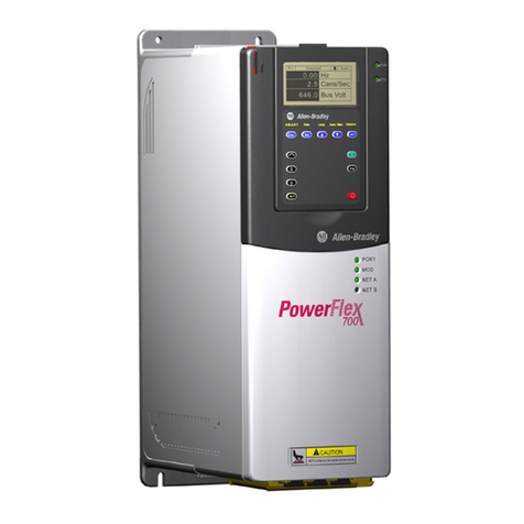
CG emotron TSA Series User manual

Emotron TSA
Softstarter
Instruction manual
English
Valid from Software version 1.27


Emotron TSA softstarter
INSTRUCTION MANUAL - ENGLISH
Valid from Software version 1.27
Document number: 01-5980-01
Edition: R2
Date of release: 28-01-2017
© Copyright CG Drives & Automation Sweden AB 2013-2017
CG Drives & Automation Sweden AB retains the right to change
specifications and illustrations in the text, without prior notification.
The contents of this document may not be copied without the explicit
permission of CG Drives & Automation Sweden AB.


CG Drives & Automation 01-5980-01r2 1
Safety instructions
Congratulations for choosing a product from CG Drives &
Automation!
Before you begin with the installation, commissioning or
powering up the unit for the first time it is very important
that you carefully study this instruction manual.
The following symbols can appear in this manual or on the
product itself. Always read these first before continuing.
Safety
The softstarter should be installed in a cabinet or in an
electrical control room.
• The device must be installed by trained personnel.
• Disconnect all power sources before servicing.
• Always use standard commercial fuses, slow blow e.g.
gl, gG types, to protect the wiring and prevent short
circuiting. To protect the thyristors against short-circuit
currents, superfast semiconductor fuses can be used if
preferred. The normal guarantee is valid even if superfast
semiconductor fuses are not used.
Operating and maintenance
personnel
1. Read the whole instruction manual before installing and
putting the equipment into operation.
2. During all work (operation, maintenance, repairs, etc.)
observe the switch-off procedures given in this
instruction as well as any other operating instruction for
the driven machine or system. See Emergency below.
3. The operator must avoid any working methods which
reduce the safety of the device.
4. The operator must do what he can to ensure that no
unauthorised person is working on the device.
5. The operator must immediately report any changes to
the device which reduce its safety to the user.
6. The user must undertake all necessary measures to
operate the device in perfect condition only.
Phase compensation capacitor
If a phase compensation capacitor is to be used, it must be
connected at the inlet of the softstarter, not between the
motor and the softstarter.
Installation of spare parts
We expressly point out that any spare parts and accessories
not supplied by us have also not been tested or approved by
us.
Installing and/or using such products can have a negative
effect on the characteristics designed for your device. The
manufacturer is not liable for damage arising as a result of
using non-original parts and accessories.
Emergency
You can switch the device off at any time with the mains
switch connected before the softstarter (both motor and
control supply voltage must be switched off).
General warnings
Alarms
Never disregard an alarm. Always check and remedy the
cause of an alarm.
NOTE: Additional information as an aid to avoid
problems.
CAUTION!
Failureto followtheseinstructions canresult
in malfunction or damage to the softstarter.
WARNING!
Failure to follow these instructions can result
in serious injury to the user in addition to
serious damage to the softstarter.
!
WARNING!
Make sure that all safety measures have
been taken before starting the motor in order
to avoid personal injury.
WARNING!
Never operate the softstarter with the front
cover removed.
WARNING!
Make sure that all safety measures have
been taken before switching on the power
supply.

2CG Drives & Automation 01-5980-01r2

CG Drives & Automation 01-5980-01r2 3
Contents
Safety instructions......................................... 1
Contents.......................................................... 3
1. Introduction..................................................... 5
1.1 Delivery and unpacking ............................................ 5
1.2 Using of the instruction manual............................... 5
1.3 Warranty .................................................................... 5
1.4 Type code number..................................................... 5
1.5 Standards .................................................................. 6
1.5.1 Product standard for EMC ........................................ 6
1.6 Dismantling and scrapping....................................... 6
1.6.1 Disposal of old electrical and electronic
equipment ................................................................. 6
1.7 Glossary ..................................................................... 7
1.7.1 Abbreviations and symbols....................................... 7
1.7.2 Definitions.................................................................. 7
2. Mounting......................................................... 9
2.1 Installation in a cabinet ............................................ 9
2.1.1 Cooling ....................................................................... 9
2.2 Mechanical specifications and drawings .............. 10
2.3 Mounting schemes.................................................. 13
3. Connections................................................. 15
3.1 Mains and motor connections ............................... 15
3.1.1 Busbar distances on Emotron TSA softatarter...... 19
3.1.2 Cable covers ............................................................ 19
3.2 Board layout and connectors ................................. 20
3.3 Control signal connections ..................................... 22
3.4 Wiring examples ...................................................... 23
4. Application guidelines ................................ 31
4.1 Softstarter dimensioning according to AC-53b..... 31
4.2 Applications rating .................................................. 31
4.3 The Application Functions List ............................... 33
4.4 Special conditions................................................... 36
4.4.1 Small motor or low load.......................................... 36
4.4.2 Ambient temperature below 0°C (32°F) .............. 36
4.4.3 Pump control with softstarter and AC drive
together ................................................................... 36
4.4.4 Starting with counter-clockwise (reverse) rotating
loads......................................................................... 36
4.4.5 Running motors connected in parallel................... 36
4.4.6 Running motors linked together ............................ 36
4.4.7 Heat dissipation in cabinets................................... 36
4.4.8 Insulation test on motor ......................................... 36
4.4.9 Operation above 1,000 m (3280 ft) ...................... 36
4.4.10 Aggressive environment conditions....................... 36
4.4.11 IT earthing system................................................... 37
4.4.12 Earth fault relay....................................................... 37
4.4.13 Other control voltage .............................................. 37
5. Getting started............................................. 39
5.1 Check list ................................................................. 39
5.2 Mains and motor connection ................................. 39
5.2.1 Connect the mains cables...................................... 39
5.2.2 Connect the motor cables ...................................... 39
5.2.3 Connect the control supply voltage ....................... 39
5.3 Default toggle loop.................................................. 40
5.4 Remote I/O operation............................................. 40
5.5 Control panel operation.......................................... 41
6. Operation via the control panel.................. 43
6.1 Display ..................................................................... 43
6.2 LED indicators ......................................................... 44
6.3 Control keys............................................................. 44
6.4 Function keys .......................................................... 45
6.4.1 +/- key function....................................................... 45
6.4.2 Jog key function....................................................... 45
6.5 Toggle and Loc/Rem Key ....................................... 46
6.5.1 Toggle function........................................................ 46
6.5.2 Loc/Rem function ................................................... 47
6.6 The menu structure ................................................ 47
6.6.1 The main menu ....................................................... 48
7. Main features............................................... 49
7.1 Setting Start, Stop and Run functions................... 49
7.1.1 Start and stop control ............................................. 49
7.1.2 Start and stop methods.......................................... 49
7.1.3 Jog functions ........................................................... 50
7.1.4 Start/Stop signal priority ........................................ 50
7.1.5 Setting motor data .................................................. 50
7.1.6 Process information................................................ 50
7.2 Working with parameter sets ................................. 51
7.2.1 Selection of parameter sets ................................... 51
7.2.2 Configuration of parameter sets ............................ 52
7.2.3 Handling motor data in parameter sets ................ 52
7.2.4 Using the control panel memory ............................ 52
7.3 Applying limitations, alarms and autoreset........... 55
7.3.1 Alarm types and actions ......................................... 55
7.3.2 Alarm settings.......................................................... 55
7.3.3 Alarm indications .................................................... 55
7.3.4 Load monitor function ............................................ 56
7.3.5 Reset and autoreset ............................................... 60
7.4 Programmable I/O .................................................. 61
7.5 Remote control functions ....................................... 61
7.5.1 Default settings of the Run/Stop/Reset
functions.................................................................. 61
7.5.2 Enable and Stop functions ..................................... 62
7.5.3 Level / Edge operation after reset......................... 62
7.6 Logical functions ..................................................... 63
7.6.1 Jog speed at Start and /or Stop............................. 63
8. Functionality................................................. 67
8.1 Preferred View [100]............................................... 69
8.1.1 1st Line [110].......................................................... 69
8.1.2 2nd Line [120] ........................................................ 69
8.2 Main Setup [200].................................................... 69
8.2.1 Operation setup [210] ............................................ 69

4CG Drives & Automation 01-5980-01r2
8.2.2 Remote signal Level/Edge [21A] ........................... 72
8.2.3 Motor Data [220] .................................................... 73
8.2.4 Motor protection [230] ........................................... 76
8.2.5 Parameter set handling [240]................................ 80
8.2.6 Autoreset [250]....................................................... 83
8.2.7 Serial Communication [260] .................................. 86
8.3 Process [300].......................................................... 89
8.3.1 View Process Value [310]....................................... 89
8.3.2 Process Settings [320] ........................................... 89
8.3.3 Start setting [330]................................................... 91
8.3.4 Stop Setting [340]................................................... 94
8.3.5 Jog [350].................................................................. 97
8.4 Load Monitor and Process Protection [400]......... 98
8.4.1 Load Monitor [410]................................................. 98
8.4.2 Process protection [420]...................................... 103
8.4.3 Mains Protection [430]......................................... 104
8.5 I/O [500]................................................................ 106
8.5.1 Analogue Input [510]............................................ 106
8.5.2 Digital Inputs [520]............................................... 108
8.5.3 Analogue Output [530] ......................................... 109
8.5.4 Relays [550] .......................................................... 112
8.5.5 Virtual I/Os [560] .................................................. 115
8.6 Logical Functions and Timers [600] .................... 116
8.6.1 Comparators [610] ............................................... 116
8.6.2 Logic outputs [620]............................................... 121
8.6.3 Timers [630].......................................................... 124
8.6.4 SR Flip-flops [640] ................................................ 125
8.6.5 Counters [650] ...................................................... 127
8.6.6 Clock Logic [660] .................................................. 128
8.7 Operation/Status [700] ........................................ 129
8.7.1 Operation values [710]......................................... 129
8.7.2 Status [720] .......................................................... 131
8.7.3 Stored Values [730].............................................. 134
8.7.4 Real time clock settings [740] ............................. 134
8.8 View Trip Log [800] ............................................... 135
8.8.1 Trip Message Log [810]........................................ 135
8.8.2 Trip Messages [820] - [890]................................. 136
8.8.3 Reset Trip Log [8A0] ............................................. 136
8.9 System Data [900]................................................ 136
8.9.1 TSA Data [920]...................................................... 136
9. Serial communication............................... 139
9.1 Modbus RTU .......................................................... 139
9.2 Parameter sets...................................................... 139
9.3 Motor data ............................................................. 140
9.4 Start and stop commands .................................... 140
9.5 Process value ........................................................ 140
9.6 Description of the EInt formats ............................ 141
10. Softstarter theory...................................... 143
10.1 Background theory................................................ 143
10.2 Reduced voltage starting...................................... 145
10.3 Other starting methods......................................... 147
10.4 Use of softstarters with torque control................ 148
11. Troubleshooting, Diagnoses and
Maintenance .............................................. 149
11.1 Trip conditions, causes and remedial action ...... 149
11.1.1 Technically qualified personnel............................ 149
11.1.2 Opening the softstarter......................................... 149
11.2 Maintenance ......................................................... 149
11.3 Troubleshooting list............................................... 150
12. Options........................................................ 155
12.1 External control panel........................................... 155
12.2 EmoSoftCom.......................................................... 155
12.3 I/O Board ............................................................... 155
12.4 PTC/PT100 ............................................................ 155
12.5 Serial communication and fieldbus ..................... 155
13. Technical data............................................ 157
13.1 General electrical specifications.......................... 160
13.2 Semi-conductor fuses........................................... 160
13.3 Environmental conditions..................................... 161
13.3.1 Derating at high temperature............................... 161
13.3.2 Derating at high altitude....................................... 162
13.4 Control power- and I/O signal connectors........... 163
Index ........................................................... 165
Appendix 1: Menu List............................... 167
Appendix 2: Trip message communication
data............................................................. 197

CG Drives & Automation 01-5980-01r2 Introduction 5
1. Introduction
The Emotron TSA softstarter is intended for controlling the
start and stop of standard three phase asynchronous motors.
A built-in powerful digital signal processor (DSP) gives the
softstarter high performance and very good control of the
starting and stopping of the application.
Several options are available, listed in chapter 12. page 155,
that enable you to customize the softstarter for your specific
needs.
Users
This instruction manual is intended for:
• installation engineers
• maintenance engineers
•operators
• service engineers
Motors
The softstarter is suitable for use with standard 3-phase
asynchronous motors. Contact your supplier for details.
1.1 Delivery and unpacking
Check for any visible signs of damage. Inform your supplier
immediately of any damage found. Do not install the
softstarter if damaged.
Check that all items are present and that the type number is
correct.
1.2 Using of the instruction
manual
Check that the software version number on the first page of
this manual matches the software version in the softstarter.
See chapter 8.9.1 page 136.
With help of the index and the table of contents it is easy to
track individual functions and find out how to use and set
them.
The Quick Start Guide can be put in a cabinet so that it is
always easy to access in case of an emergency.
1.3 Warranty
The warranty applies when the equipment is installed,
operated and maintained according to instructions in this
instruction manual. Duration of warranty is as per contract.
Faults that arise due to faulty installation or operation are
not covered by the warranty.
1.4 Type code number
Fig. 1 gives an example of the type code numbering used for
the Emotron TSA softstarter. This identification will be
required for type specific information when mounting and
installing. The code number is located on the product label,
on the right side of the unit (when viewed from the front).
Fig. 1 Type code number
NOTE: Read this instruction manual carefully before
installing, connecting or working with the softstarter.
TSA 52 -016 -23 N N N —AA—
Position number:
1 2 3 4 567891011
Ta b l e 1
Position Configuration Description
1Type TSA
2 Main supply voltage 52 = Max 525 V mains
69 = Max 690 V mains
3 Current rating
016 = 16 A
-
- 1K8 = 1800 A
4 Control voltage 23=230 V
5 Option position 1
N=No option
P=PTC/PT100
I=I/O board
6 Option position 2
N=No option
P=PTC/PT100
I=I/O board
7Communication
option
N=No option
A=Profinet IO 1-port
B=Profinet IO 2-port
D=DeviceNet
E= EtherCAT
G=EtherNet/IP 2-port
M=Modbus/TCP
P=Profibus
R=RS485
U=USB
8 Supply type
—=Standard (Grounded
net)
I=IT-net (EMC not fulfilled)
9Brandlabel A=Standard
10 Software A=Standard software
11 Standard —=CE approved
U=UL/cUL approved

6Introduction CG Drives & Automation 01-5980-01r2
1.5 Standards
The softstarters described in this instruction manual comply
with the standards listed in Table 2. For the declarations of
conformity and manufacturer’s certificate, contact your
supplier for more information or visit www.emotron.com or
www.cgglobal.com.
1.5.1Product standard for EMC
The Emotron TSA softstarter complies with the product
standard EN(IEC) 60947-4-2: 2007. The standard
Emotron TSA softstarters are designed to meet the EMC
requirements according to:
Category C1 - Emotron TSA -frame sizes 1 & 2
Category C2 - Emotron TSA -frame sizes 3 & 4 .
1.6 Dismantling and scrapping
The enclosures of the Emotron TSA softstarters are made
from recyclable material such as aluminium, iron and
plastic. Each softstarter contains a number of components
demanding special treatment. The circuit boards contain
small amounts of tin and lead. Any local or national
regulations in force for the disposal and recycling of these
materials must be complied with.
1.6.1Disposal of old electrical and
electronic equipment
This symbol on the product or on its
packaging indicates that this product shall be
taken to the applicable collection point for the
recycling of electrical and electronic
equipment. By ensuring this product is
disposed of correctly, you will help prevent potentially
negative consequences for the environment and human
health, which could otherwise be caused by inappropriate
waste handling of this product. The recycling of materials
will help to conserve natural resources. For more detailed
information about recycling this product, please contact the
local distributor of the
product.
Ta b l e 2 St a n d a r d s
Market Standard Description
European
EMC Directive 2004/108/EC
Low Voltage Directive 2006/95/EC
WEEE Directive 2002/96/EC
All
EN 60204-1 Safety of machinery - Electrical equipment of machines
Part 1: General requirements.
EN(IEC)60947-4-2:
2007
Contactors and motor starters
Part 3: EMC requirements and specific test methods.
EMC Directive: Declaration of Conformity and CE marking
EN(IEC)60947-4-2:
2007
Contactors and motor starters
Safety requirements - Electrical, thermal and energy.
Low Voltage Directive: Declaration of Conformity and CE marking
IEC 60721-3-3 Classification of environmental conditions. Air quality chemical vapours, unit in
operation. Chemical gases 3C3, Solid particles 3S1.
DNV-GL DNV-GL Marine standard
North & South
American
UL508C UL Safety standard for Power Conversion Equipment.
UL 840 UL Safety standard for Power Conversion Equipment.
Russian EAC For all sizes

CG Drives & Automation 01-5980-01r2 Introduction 7
1.7 Glossary
1.7.1Abbreviations and symbols
In this manual the following abbreviations are used:
1.7.2Definitions
In this manual the following definitions are used:
*) Calculation of nominal motor torque:
Table 3 Abbreviations
Abbreviation/
symbol Description
CP Control panel, the programming and
presentation unit on the softstarter
CB Control board
I2t The amount of energy losses, heating up the
motor.
PTC
Positive Temperature Coefficient
(temperature sensor, also known as
thermistor)
PB-PTC Power board PTC input
RMS Root Mean Square value
FLC Full Load Current
DOL Direct On-Line
EInt Communication format
UInt Communication format (Unsigned Integer)
Int Communication format (Integer)
Long Communication format (Integer Long)
SELV Safety Extra Low Voltage
The function cannot be changed in run mode
Table 4 Definitions
Name Description Unit
In_soft Nominal softstarter current [Arms]
In_mot Nominal motor current [Arms]
Pn_soft Nominal softstarter power [kW] or [hp]
Pn_mot Nominal motor power [kW] or [hp]
TnNominal motor torque* [Nm] or [lb.ft]
nn_mot Nominal speed of motor [rpm]
cosϕnNominal motor power factor (dimensionless)
U 3-phase mains supply voltage [Vrms]
Un_mot Nominal motor voltage [V]
TnNm[]
9550 PnmotkW[]×
nnmotrpm[]
-----------------------------------------------
=
Tnlbft[]
5252 Pnmothp[]×
nnmotrpm[]
----------------------------------------------
=

8Introduction CG Drives & Automation 01-5980-01r2

CG Drives & Automation 01-5980-01r2 Mounting 9
2. Mounting
This chapter describes how to mount the Emotron TSA
softstarter. Before mounting it is recommended that the
installation is planned out:
• Be sure that the softstarter suits the mounting location.
• The mounting site must support the weight of the
softstarter.
• Will the softstarter continuously withstand vibrations
and/or shocks?
• Consider using a vibration damper.
• Check ambient conditions, ratings, required cooling air
flow, compatibility of the motor, etc.
• Do you know how the softstarter will be lifted and
transported?
Make sure that the installation is performed in accordance
with the local safety regulations, and in accordance with
DIN VDE 0100 for setting up power installations.
Care must be taken to ensure that personnel do not come
into contact with live circuit components.
2.1 Installation in a cabinet
When installing the softstarter:
• Ensure that the cabinet will be sufficiently ventilated
after the installation.
• Keep the minimum free space, as listed inTable 5.
• Ensure that air can flow freely from the bottom to the
top.
The Emotron TSA softstarters are delivered as enclosed
versions with front access cover. The units have top and
bottom entry for cables etc., see Chapter 3. page 15.
2.1.1 Cooling
WARNING!
Never operate the softstarter with the front
cover removed.
NOTE: When installing the softstarter, make sure it does
not come into contact with live components. The heat
generated must be dispersed via the cooling fins to
prevent damage to the thyristors (free circulation of air).
Table 5 Minimum free space
TSA
Frame size
Minimum free space
mm (in)
above* below at side
1
100
(3.9)
100
(3.9) 0
2
3
4
*) Above: Cabinet roof to softstarter or softstarter to softstarter

10 Mounting CG Drives & Automation 01-5980-01r2
2.2 Mechanical specifications and drawings
*) H1 = Height of enclosure.
H2 = Total mounting height of unit.
H3 = Total height including Cable covers.
Emotron TSA frame size 1 - 2
Fig. 2 Dimensions for Emotron TSA frame size 1 and 2.
Fig. 3 Dimensions for Emotron TSA frame size 1 and 2,
bottom view.
Ta b l e 6
TSA
Frame
size
Dimensions*
H1/H2/H3 x W x D
[mm (in)]
Mounting
position
[Vertical/
Horizontal]
Weight
[kg(lb)]
Connection
busbars and
pressnut
dimension
[mm (in)]
PE
screw Cooling
system Protection
class
1246/296/340 x 126 x 188
(9.7/11.7/13.4 x 5 x 7.4)
Vertical 5.5
(12.1) 15 x 2
(0.59 x 0.08)
M6 connection
M5
Convection
IP20
2
Vertical/
Horizontal
5.7
(12.6) Fan
3285/323/380 x 196 x 235
(11.2/12.7/14.9 x 7.7 x 9.3)
13
(28.7)
20 x 5
(0.8 x 0.20)
M10 connection
M8 Fan IP20
4378/411/514 x 254 x 260
(14.9/16.2/20.2 x 10 x 10.3)
23.5
(51.8)
40 x 10
(1.6 x 0.39)
Ø 13 connection
M8 Fan IP20
H1 H2
WD
H3
188 (7.4)

CG Drives & Automation 01-5980-01r2 Mounting 11
Emotron TSA frame size 3
Fig. 4 Dimensions for Emotron TSA frame size 3.
Fig. 5 Dimensions for Emotron TSA frame size 3, bottom
view.
H1 H2
196 (7.7) 235 (9.3)
H3
235 (9.3)

12 Mounting CG Drives & Automation 01-5980-01r2
Emotron TSA frame size 4
Fig. 6 Dimensions for Emotron TSA frame size 4 .
Fig. 7 Dimensions for Emotron TSA frame size 4, bottom
view.
H1 H2
254 (10) 260 (10.3)
H3
260 (10.3)

CG Drives & Automation 01-5980-01r2 Mounting 13
2.3 Mounting schemes
Emotron TSA frame size 1 - 2
Fig. 8 Hole pattern for Emotron TSA frame size 1 and 2.
Emotron TSA frame size 3
Fig. 9 Hole pattern for Emotron TSA frame size 3.
Emotron TSA frame size 4
Fig. 10 Hole pattern for Emotron TSA frame size 4.
On our websites www.cgglobal.com and www.emotron.com
it is possible to download a full-size template for positioning
of the fixing holes.
104.5 (4.1)
11(0.43)
273(10.7)
Ø 6,5 (x 4)
11
(043)
170(6.7)
13(0.51)
303(12)
10
Ø 13
Ø 7 (x 4)
(039)
4
25
,
5
220(8.7)
17(0.67)
390(1.4)
Ø 7 (x 4)
11
Ø 13
(043)

14 Mounting CG Drives & Automation 01-5980-01r2

CG Drives & Automation 01-5980-01r2 Connections 15
3. Connections
The installation description in this chapter follows the EMC
standards and the Machinery Directive.
If the softstarter is temporarily stored before being
connected, please check the technical data for environmental
conditions section 13.3, page 161. If the softstarter is moved
from a cold storage room to the location where it is to be
installed, condensation could appear on the unit. Allow the
softstarter to become fully acclimatised and wait until any
visible condensation has evaporated before connecting any
supply voltages.
Cables
Dimension the mains and motor cables according to local
regulations and the nominal current of the motor. It is
possible to use either copper or aluminium cables.
It is not necessary to use shielded motor cables together with
the Emotron TSA softstarter. This is due to its very low
radiated emissions.
Neither is it necessary to use shielded mains supply cables
for the Emotron TSA softstarter.
For control signal cables it is not mandatory to use shielded
cables to fulfil the EMC regulations (section 1.5, page 6) but
it is recommended in general to avoid disturbances.
3.1 Mains and motor
connections
Fig. 11 Mains, motor and control supply voltage connection
NOTE: The Emotron TSA control-board is equipped with a
ground plane to which shielded cables can be
connected (see Fig. 17 on page 21).
NOTE: For UL-approval use 75°C copper wire only.
100 - 240 VAC

16 Connections CG Drives & Automation 01-5980-01r2
Emotron TSA frame size 1 - 2
Fig. 12 Mains and motor connections for Emotron TSA Size 1-2.
1. 3-phase mains supply connection, L1, L2, L3
2. Protective earth (PE) connection for mains supply
3. Motor power supply connection T1, T2, T3
4. Motor earth, connection
PE
T1 T2 T3
L1 L2 L3
L1 L2 L3
T1 T2 T3
3
4
2
1
WARNING!
Leakage current may occur from the
thyristors when a 3-phase mains supply is
connected. Full voltage can be detected if no
motor is connected.
Table 7 Tightening torque for bolts [Nm (Lb-in)].
TSA
Frame size
Tightening torque for bolts
[Nm (Lb-in)]
Motor or mains
cables PE cable
1 8 (70) 5 (44)
2 8 (70) 5(44)
This manual suits for next models
1
Table of contents
Other CG Controllers manuals
