+0500016RU - rel. 1.2 - 13.04.2011
Электронный контроллер для систем вентиляции и кондиционирования (настенный
монтаж) / Electronic controller for air-conditioning (ush-mount model)
AT* - th Tune
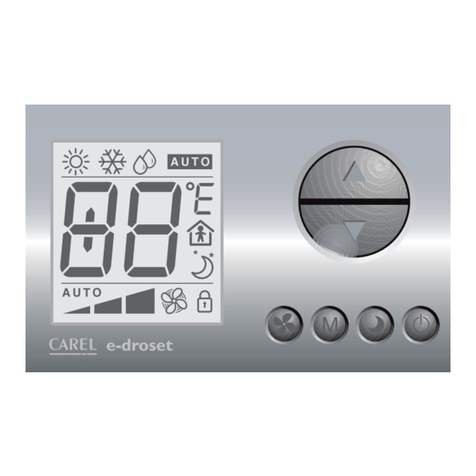
th-Tune – это комнатный терминал CAREL, который совместно
с программируемыми контроллерами рСО*, позволяет
пользователю управлять температурой и влажностью в жилых
помещениях. В зависимости от модели, терминал может
быть с датчиком температуры или датчиками температуры
и влажности, и напряжением питания 230В или 24В перем/
пост. Настойки температуры и влажности интуитивно понятны
и просты, и выполняются с помощью поворотной рукоятки
на передней панели. th-Tune также позволяет пользователю
задать некоторые уставки, такие как рабочий режим и
временной диапазон. Тип управления и показания зависят
исключительно от контроллера, к которому подключен th-
Tune. Компактные размеры и элегантный дизайн делают его
подходящим ко всем типам помещений.
Код Модель
ATA******* напряжение питания 230В
ATC******* напряжение питания 24В ас/dc
AT******D* скрытый монтаж
AT*****A** с датчиком температуры
AT*****C** с датчиком температуры и влажности
AT*M****** мембранная клавиатура
Tab. 1
Особенности установки
• Эти терминалы были разработаны для скрытой установки
в монтажные коробки, соответствующие действующим
стандартам.
• Перед выполнением любых операций с терминалом,
отключите питание от устройства, путем отключения от
электрической сети. Затем снимите фронтальную панель
для доступа к терминалу подключения.
• для версий 24В ac используйте трансформатор класса 2,
мощностью 2 ВА
• если для питания терминала используется общий с
контроллером трансформатор, то клемма питания
терминала GND должна быть подключена к линии питания
контроллера GND;
• при необходимости заземления терминала с питанием
24Вас/24Вdc используйте клеммы GND th-Tune и других
устройств;
• при питании th-Tune постоянным напряжением, контроллер
подключенный по сети также должен быть запитан
постоянным напряжением. Если контроллер не имеет
постоянного напряжения питания, th-Tune также не может
быть запитан постоянным напряжением;
• для сетевого подключения используется трехжильный
экранированный кабель AWG 20-22. Протяженность сети
не более 500 м. Для распространенных сетей используйте
резистор 120 Ом между TX+ и RX/TX- на первом и последнем
устройстве, во избежание проблем коммуникации.
Подключение
Для установки задней части терминала используйте монтажную
коробку с диаметром мин. 65 мм и глубиной мин. 31 мм.
1. отделите фронтальную часть терминала от тыльной при
помощи отвертки (Рис.1);
2. Отсоедините 4х штырьковый разъем от фронтальной
панели (рис.2);
3. выполните электрические присоединения:
• для моделей 230В см. Рис.4
• для моделей 24Вас/24Вdc см. Рис.3; убедитесь в
правильности полярности (24В , GND) для постоянного
напряжения;
4. закрепите тыльную часть в коробке прилагаемыми винтами:
• для моделей AT******D* крепление винтов показано на
Рис.6 и 7;
5. присоедините обратно 4х штырьковый разъем ;
6. установите терминал, начиная снизу, убедившись, что все
провода внутри и не препятствуют закрытию до щелчка.
Демонтаж
Вставьте отвертку в паз сверху и нажмите вниз для снятия
дисплея.
Общие замечания
Избегайте установки в местах со следующими
характеристиками:
• относительная влажность превышает значение, указанное в
технических характеристиках;
• сильная вибрация или удары;
• контакт с распыленной водой;
• воздействие агрессивных и загрязняющих факторов
(например пары серы и аммиака, солевой туман, дым)
во избежание коррозии и/или окисления;
• сильные магнитные и/или радио частотные помехи
(например вблизи передающих антенн);
• воздействие прямых солнечных лучей;
• большие и быстрые флуктуации температуры в комнате;
• в местах присутствия взрывоопасных или горючих газов;
• воздействие пыли (образование коррозии и возможность
окисления и снижения изоляции).
86
86
8 22,55 28
48
Размеры (мм) / Dimensions (mm)
Демонтаж / Dismantling
Подключение / Wiring
24 Vac/dc 230 Vac
GND
Rx+/Tx+
Rx–/Tx–
GND
24V~/24V
GND
Rx+/Tx+
Rx–/Tx–
N230V~
L 50/60Hz
Fig. 3 Fig. 4
Fig. 1
Fig. 2
th-Tune is the Carel room terminal that, together with the
pCO* programmable controller, allows the user the control
the temperature and humidity in residential environments.
Depending on the model, the terminal is tted with a temperature
probe or temperature and humidity probe, and power
supply may be 230 Vac or 24 Vac/Vdc. th-Tune is compatible
with the main ush mount distribution boxes available on
the market (IT, US, DE, CN). Temperature and humidity set
is simple and intuitive, using the knob on the front panel.
th-Tune also allows the user to make some settings,
such as the operating mode and time bands.
The type of control and displays depend exclusively on the
controller that th-Tune is connected to. The compact dimensions
and elegant design make it suitable for all types of rooms.
Code Model
ATA******* 230 Vac power supply
ATC******* 24 Vac/Vdc power supply
AT******D* ush mount
AT*****A** with temperature probe
AT*****C** with temperature and humidity probe
AT*M****** membrane keypad
Tab. 1
Installation warnings
• These terminals have been designed for ush mount assembly,
on distribution boxes compliant with the standards in force;
• before performing any operations on the terminal, disconnect
the power supply from the device by switching the main switch
on the electrical panel OFF. Then remove the front part of the
terminal from the rear to make the electrical connections;
• for the 24 Vac version use a class 2 power transformer with
minimum rating of 2 VA;
• if the transformer used for the terminal is the same for the
controllers connected to the serial line, the power supply GND
terminal on the th-Tune must be connected to the controller
power supply GND line;
• if a power terminal on the 24 Vac/24 Vdc version needs to be
earthed, use the GND terminal, both for the th-Tune that the
other powered devices;
• when th-Tune has a DC power supply, the controllers connected
to the serial line must also have a DC power supply. If the
controllers do not allow DC power, then th-Tune cannot use the
DC power supply;
• for the serial connection use three-wire shielded cable, AWG
20-22. The length of the network must not exceed 500 m.
For extended networks t a 120 Ohm resistor between RX/
TX+ and RX/TX- on the rst and last device, to avoid possible
communication problems.
Assembly
To t the rear part of the terminal use a ush mount box with a
min. diameter of 65 mm and a minimum depth of 31 mm.
1. detach the front from the rear of the terminal using a
screwdriver (Fig. 1);
2. disconnect the 4-pin connector from the front part (Fig. 2);
3. make the electrical connections:
• for 230 models Vac see Fig. 4;
• for 24 Vac/24 Vdc models see Fig. 3; make sure the polarity
(24 V , GND) is right for direct current power supply;
4. fasten the rear to the ush mount box using the 2 screws
supplied:
• for models AT******D* insert the screws as shown in Fig. 6 and 7;
5. plug the 4-pin connector back in;
6. nally reposition the terminal, starting from the bottom tabs
using a hinge movement. Make sure that the electrical wires
are in position to ensure the terminal clicks into place.
Dismantling
Insert a screwdriver into the clot at the top (Fig. 1) and press
downwards to detach the display.
General notes
Avoid installing the terminal in environments with the following
characteristics:
• relative humidity greater than the value specied;
• strong vibrations or knocks;
• exposure to water sprays;
• exposure to aggressive and polluting atmospheres(e.g.: sulphur
and ammonia fumes, saline mist, smoke) so as to avoid corrosion
and/or oxidation;
• strong magnetic and/or radio frequency interference (for
example, near transmitting antennae);
• exposure to direct sunlight or the elements in general;
• large and rapid uctuations in the room temperature;
• environments where explosives or mixes of ammable gases
are present;
• exposure to dust (formation of corrosive patina with possible
oxidation and reduction of insulation).
