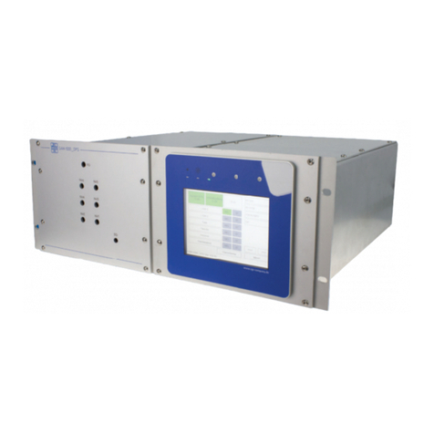
CGS SAM-1000 DPS User manual

SAM-1000_DPS
Operating instructions
Language: English
Revision: Version 2.0 (Software V3.0.1)
Issue: June 2022
NOTE
Read these operating instructions carefully before assembly,
installation and implementation.
These operating instructions are also available as a digital document on:
www.cgs-company.de/downloads/MDZ_E_B_SAM-1000_DPS.pdf
MDZ_E_B_SAM-1000_DPS_2.0


3/55
E
Product:
SAM-1000_DPS Revision 2.0 – Issue June 2022
Table of contents
Table of contents ..............................................................................3
1 General information ..........................................................................5
1.1 Device version and validity ..............................................................5
1.2 Information for our customers...........................................................5
1.3 General...............................................................................5
1.4 Warnings and explanatory texts .........................................................5
1.5 Intended use ..........................................................................6
1.6Qualiedpersonnel ....................................................................6
1.7 Warranty information ..................................................................6
1.8 Delivery information ...................................................................7
1.9 Norms and regulations .................................................................7
1.10 Disclaimer ...........................................................................8
1.11 Disposal .............................................................................8
2 Warnings and safety instructions...............................................................9
3 Packaging and transport .....................................................................10
3.1 Packaging material ....................................................................10
3.2 Shipping labels .......................................................................10
3.3 Transport inspection ..................................................................11
3.4 Storage..............................................................................11
4 Installation, assembly information.............................................................12
5 Setup and function ..........................................................................13
5.1 Functional description .................................................................13
5.2 Mechanical design ....................................................................15
5.3 Dimensional drawing..................................................................15
5.4 Connection drawing...................................................................16
5.5Gasowschematic....................................................................17
5.5.1Gasowschematictype1,withoutbypass .........................................17
5.5.2Gasowschematictype2,withbypass3/2-way ....................................18
5.5.3Gasowschematictype3,withbypass............................................19
5.6 Electrical connection ..................................................................20
6 Operation Touch-Panel ......................................................................22
6.1 Main menu...........................................................................22
6.2 Device overview ......................................................................23
6.3Gasowscheme......................................................................24
6.4 Menu ...............................................................................25
6.5 Language ............................................................................26
6.6 Parameter ...........................................................................26
6.7 Network .............................................................................26
6.8 SNMP ...............................................................................27
7Probusconguration .......................................................................28
7.1Activationoftheprobusmaster........................................................34
8 Application example .........................................................................35
9 Maintenance & repair ........................................................................36
9.1Replacingthesolenoidvalves/replacingthelter .........................................36
10 Cleaning ..................................................................................37
10.1 Cleaning the surface..................................................................37

4/55
E
Product:
SAM-1000_DPS Revision 2.0 – Issue June 2022
10.2 Cleaning the interior .................................................................37
10.3 Cleaning the control panel ............................................................37
11 Connection options.........................................................................38
12 Technical data .............................................................................39
13 Order numbers ............................................................................40
14 Delivery contents ..........................................................................41
15 Spare part list..............................................................................42
16 Appendix A (EU Declaration of Conformity) ....................................................43
17 Appendix B (Inspection protocols) ............................................................44

5/55
E
Product:
SAM-1000_DPS Revision 2.0 – Issue June 2022
1 General information
1.1 Device version and validity
Thisdocumentationisrestrictedtothespeciedproductandisonlyvalidforthisrespectiveproduct.The
documentation describes the installation, implementation and maintenance of the device and provides
information about its function.
1.2 Information for our customers
Read this manual before commencing work on this device! It contains important information and data that,
when observed, will ensure the device functions properly and save service costs. Implementation of this
device is thereby considerably facilitated, leads to reliable measurement results and prevents damage
caused by improper use of the product.
1.3 General
This device has left the factory in a technically and operationally safe condition. To maintain this condition
andtoensuresafeoperationofthisproduct,itmustbeimplementedonlyinthemannerspeciedbythe
manufacturer. In addition, correct and safe operation of this product depends upon proper transport,
proper storage and installation as well as careful operation and maintenance.
This manual contains the information necessary for the proper use of the product described herein.
Itiswrittenfortechnicallyqualiedpersonnelwhoarespeciallytrainedorhaverelevantknowledgeinthe
eldofautomationtechnology(measurement,controlandfeedbackcontrolsystems).
Knowledge and technically correct implementation of the safety instructions and warnings contained in this
manual are required for the safe installation and implementation of the product described and for its safety
duringoperationandmaintenance.Onlyqualied personnelhavethenecessary expertise tointerpret the
generallyapplicablesafetyinstructionsandwarningsinspeciccasesandtoapplytheminpractice.
This manual is an integral part of the scope of delivery even if a separate order is possible due to logistical
reasons.
Because of the large number of technical details, it is not possible to consider all the details for all versions of
the described product and for every conceivable installation, operation, maintenance and implementation
in systems.
Ifyouneedadditionalinformation,orshouldparticularproblemsarisewhicharenotsucientlycoveredin
this document, please request the necessary information from your local or responsible CGS representative.
1.4 Warnings and explanatory texts
This manual describes how you can properly run, commission, operate and maintain this device.
You must pay particular attention to all warning and explanatory texts. These are separated from the text
andspecicallyidentiedbytherelevanticons.Theyprovideyouwithvaluabletipsforavoidingoperating
errors and accidents.

6/55
E
Product:
SAM-1000_DPS Revision 2.0 – Issue June 2022
1.5 Intended use
The intended use for the purposes of this manual means that this product must only be used for the
applications described in the catalogue and in the technical description and only in conjunction with external
devices and components approved or recommended by CGS.
The product described in this manual has been developed, manufactured, tested and documented in
compliance with the applicable safety standards. No danger to personal health or property damage
therefore normally ensues from compliance with the handling guidelines and safety instructions described
for its project planning, assembly, intended use and maintenance.
1.6 Qualified personnel
Only those persons who are familiar with the installation, assembly, implementation and operation of the
productarequalied.
Thesepersonshavethefollowingqualications:
• They are authorised, trained or instructed to operate and maintain equipment and systems in accordance with
established safety procedures for electrical circuits, high pressures and aggressive and hazardous media.
• For devices with explosion protection: They are authorised, trained or instructed in carrying out work on
electrical circuits for hazardous systems.
• They are trained or instructed in the maintenance and use of protective equipment in accordance with
established safety procedures.
1.7 Warranty information
The contents of this manual is neither part of any previous or existing agreement, commitment or a previous
or existing legal relationship, nor should anyone modify these. All obligations by CGS arise from the respective
sales contract, which also contains the complete and solely applicable warranty terms and conditions.
These contractual warranty regulations are neither extended nor limited by the contents of the manual.
The manufacturer accepts no liability for damage or malfunctions resulting from failure to observe the
operating instructions.
Apart from the operating instructions and regulations regarding accident prevention applicable in the
country and place of use, you must also observe the recognised technical regulations for safe and proper
work.
The warranty claim expires if the device is not installed, implemented, operated and maintained in
accordance with regulations.

7/55
E
Product:
SAM-1000_DPS Revision 2.0 – Issue June 2022
Proper maintenance means:
• Adherence to the maintenance plan (see Chapter: Maintenance)
• Maintenance by trained maintenance personnel
• Use of original CGS spare parts
Maintenance should be performed by the CGS service technician or, on the operator side, by CGS-trained
service technicians.
The warranty is void in case of:
• improper use
• use of unauthorised equipment
• faulty connection and existing components that are not part of the scope of delivery and service
• failure to use original spare parts and accessories
• retrottingthatwasnotperformedbyCGSitself
• non-compliance of prescribed maintenance work
Thecontentsreectthestateoftheartatthetimeofpublication.
We reserve the right to make any technical changes due to further development.
1.8 Delivery information
The respective scope of delivery is listed in the shipping documents accompanying the delivery based on
the valid contract.
Please observe the corresponding information on the packaging material when opening the packaging.
Check the delivery for completeness and intactness. In particular, you should, where applicable, compare
the order number on the nameplates with the ordering data.
Ifpossible,pleasekeepthepackagingmaterialssothatyoucanuseitforfuturereturndeliveries(seeChapter:
Packaging and transport).
1.9 Norms and regulations
ThespecicationandproductionofthisdevicewerebasedontheharmonisedEuropeanNormswhenever
possible. If no harmonized European Norms have been applied, then the norms and regulations of the
Federal Republic of Germany shall apply.
When using this product outside the scope of these norms and regulations, you must comply with the norms
and regulations valid in the operator's country.

8/55
E
Product:
SAM-1000_DPS Revision 2.0 – Issue June 2022
1.10 Disclaimer
All technical information, data and operating instructions contained in this manual correspond to the
latest state of development at the creation of this manual and are based on our previous experience and
knowledge to the best of our knowledge.
We reserve the right to make any technical changes in the course of further development of the device
described in these operating instructions. No claims can be derived from the data, illustrations and
descriptions in this manual.
We assume no liability for any damage and interruptions caused by operator error, non-observance of these
operating instructions or improper repairs.
We expressly state that only original spare parts and accessories approved by us must be used. This also
applies to the subassemblies of other manufacturers.
Theinstallationoruseofnon-approvedreplacementpar tsandaccessoriesandanyunauthorisedmodications
and changes are not permitted for safety reasons and exclude liability by CGS for any resulting damages.
Claims for damages are excluded regardless of the legal grounds of such claims.
Translations are made in good faith. We cannot accept any liability for any translation errors not even when
the translation was made by us or on our behalf. Only the original text is binding.
Thetextandillustrationsdonotnecessarilyreectthescopeofdeliveryorapossiblesparepartsorder.
The drawings and diagrams are not to scale.
1.11 Disposal
This product comes from an environmentally conscious manufacturer and complies with the
2012/19/EU directive on waste electrical and electronic equipment (WEEE).
Thisproductmaycontainsubstanceswhich,ifimproperlydisposedof(landlls,incinerators),are
potentially environmentally harmful. It must therefore not be disposed of in this way.
Therefore, behave environmentally conscious:
• Arrange for this product to be recycled at the end of its life cycle via the relevant on-site facilities!
• Observe the relevant regulations for your country!

9/55
E
Product:
SAM-1000_DPS Revision 2.0 – Issue June 2022
2 Warnings and safety instructions
This manual contains important Warnings and safety instructions which you must observe to ensure
your own personal safety and to avoid property damage. The instructions referring to your personal safety
are indicated by a warning symbol. Instructions referring only to property damage have no warning symbol.
Depending on the hazard level, warnings are displayed in descending order as follows.
If more than one hazard level occurs then the warning representing the highest degree of danger will be
used. If a warning triangle is used to warn against personal injury then the same warning can be added to
warn against property damage.
DANGER
indicates that death or severe personal injury will result if no appropriate precautions are taken.
WARNING
indicates that death or severe personal injury can result if no appropriate precautions are taken.
CAUTION
with warning triangle indicates that minor personal injury can result if no appropriate precautions are taken.
NOTE
means that an undesirable event or situation can occur if the corresponding information is not observed.
CAUTION
without warning triangle indicates that property damage can result if no appropriate precautions are taken.

10/55
E
Product:
SAM-1000_DPS Revision 2.0 – Issue June 2022
3 Packaging and transport
3.1 Packaging material
The individual system components and modules are shipped in dierent packaging. Primary packaging
materials: wood, cardboard and plastics (lms, foams), but also including hoop iron (for bundles), for
example. Packing materials include materials which are added to the packages for moisture protection (e.g.
silica gel bags).
If no agreement was reached on returning the packaging material then the packaging material remains with
the customer.
Waste disposal that is environmentally friendly and in accordance with the applicable disposal regulations
must be ensured. If necessary, assign waste disposal companies with the disposal of the packaging material.
The system components are to be transported as far as possible in the package to the installation site and
kept in the package until assembly.
3.2 Shipping labels
Symbols are attached on the packages which must be observed during all transport phases including stor-
age.
1. TOP! The package must be stored, handled and transported in such a way that the arrows always point
upwards. Rolling, swinging, severe tipping or walking of goods marked in this way must be avoided.
2. Do not use forklift truck here
3. Do not destroy barrier!
4. Fragile, handle with care! Goods marked with this symbol should be handled carefully and should never
be rolled over or tied tightly.
5. Keep dry. Since goods of this type should also be protected from high levels of humidity, they must be
transported in closed vehicles or containers.
6. Center of gravity. This symbol is intended to provide a clear indication of the position of the center of
gravity.

11/55
E
Product:
SAM-1000_DPS Revision 2.0 – Issue June 2022
3.3 Transport inspection
Important:
Check the entire shipment for completeness and possible transport damage immediately upon arrival.
Failure to observe the following instructions in the event of damage shall cease the obligation of the insurer
to render performance.
• Even in case of suspected damage: Only acknowledge receipt with reservation (e.g. including shipping
documents) by specifying the alleged damage.
• Assert claims for compensation against third parties:
Carriers, freight forwarders, warehouse keepers:
- demand joint damage inspection
-requestacerticateofdamage
- hold these liable for damages in writing and describe the damage in detail,
namely:
- in case of visible damage prior to accepting delivery of the goods
- in case of no apparent outward damage immediately upon discovery
• Set deadlines for complaints and observe these!
• Ensure mitigation of incurred damage and avoidance of further damage.
• Immediately consult an insurance adjuster to record the damage and provide advice for securing claims
against third parties and for measures to mitigate the damage incurred.
• Never change the status of the consignment and its packaging until the arrival of the adjuster insofar this
is not required to mitigate and prevent further damage.
• Immediately notify the insurer about the insurance case and quickly submit the complete claim documents
to accelerate claims settlement (latest time before any preclusion and/or limitation periods for claims
against third parties).
3.4 Storage
After unloading, the packages must be stored until installation in accordance with the shipping markings.
Packed machine parts and accessories may not be unpacked.
Observe the applicable regulations for storage:
• Store in a cool dry place. Maximum humidity: 60 %.
Make sure the packages are not stored outdoors.
Alsoensurethatthestorageroomoorisdryduringstorage.
• Protectagainstdirectsunlight.Storagetemperature5°Cto35°C.
• Store in a dust-free location!
• Avoid mechanical shock and damage.
• For longer storage over 3 months, check the conservation measures.
In case of aggressive weather conditions, conservation must be renewed if necessary.

12/55
E
Product:
SAM-1000_DPS Revision 2.0 – Issue June 2022
4 Installation, assembly information
Safety measures:
Installationandassemblymustonlybeperformedbyspeciallytrainedandqualiedpersonnel.Thegeneral
accident prevention regulations must thereby be observed.
A formal handover to the operator occurs in case of implementation by CGS or its authorised representatives.
The device can subsequently be properly operated according to the operating instructions and applicable
safety regulations.
Before opening the device, disconnect it from the power supply in any case.
Requirements for the installation site:
• No exposure to direct sunlight
• Low exposure to dust
• Sucientspaceforoperationandmaintenance
• Available and easily accessible escape routes
• No tripping hazards caused by cables that run close to the ground, etc.
• Maximum height: 2000 m above sea level
Technical prerequisites (supply voltage, gas pressures, etc.) can be found in the Technical Data section.

13/55
E
Product:
SAM-1000_DPS Revision 2.0 – Issue June 2022
5 Setup and function
5.1 Functional description
ThecabinetsamplemoduleseriesSAM-1000_DPSisusedtoconnectdierentsamplepointstoanalysers.
Because of its modular design, it can be used for various applications in the chemical and petrochemical
industries for gaseous high-purity gases.
Special features:
The SAM-1000_DPS especially distinguishes itself through the following features:
• Compact design
• Low dead volume
• Modular design
• High tightness
• Wide range of use
• Digitisation of the complete product measurement
• Remote control by Ethernet; TCP/IP
•
The SAM-1000_DPS can be equipped with up to 6 sample streams (S1-S6) a switched to several analyzers. On
rearsideofthemodulethesampleconnectorsarebasicallyequippedwithtwo-ferrulettings.
One sample gas and one bypass valve are actuated for each sample stream. The sample gas valve route the
gas to the analysis system. Ensure in automatic mode (DCS operation) one sample gas valve is continuously
activated to supply the analysis system with gas. The functionality of the bypass valve is to purge the sample
streambeforeitwillbemeasured.Thisensuresafastsupplyoffreshgastothesystem.Thegasowofthe
bypasspurgemustbeadjustedbyamechanicalowmeterandisdisplayedbyanelectronicowmeterin
thetouchscreenofthemodule.Theregulatingscrewofthegasowisaccessibleviaaholeinthefrontplate
and can be adjusted by an Allen key (size 3). The duration and amount of the sample purge procedure is pre-
calculated based on the length and diameter of the tube.
TherearedierentalternativestoorderaSAM-1000_DPSmodule.Thedierencesarebasicallythetypeof
the continuous bypass switching.
Version Type of continuous bypasses Application exapmle
1Without • Plants without continuously purged gas tubes; for
examplecylinderlling
• Plants with low or expensive gas products; for ex-
ample He, Ne, Xe, Kr, etc.
2 Bypass for all sample streams with
needle valve and 3/2- Way valve
to switch between atmosphere
andelectronicalowmeterfor
adjustment
Plants with continuously purged gas tubes from the
tank, which require a very fast response of the analy-
sissystemafterswitchover;forexampletrucklling
& tank farms of liquid O2, N2, Ar, CO2, etc.
3 Bypass for all sample streams with
needlevalveandelectronicalow
meter for adjustment

14/55
E
Product:
SAM-1000_DPS Revision 2.0 – Issue June 2022
This3alternativesarealreadyprogrammedintheSAM-1000_DPSSoftwareandwouldbepre-denedbe-
fore delivery. Depending on the type, the sample streams are equipped with one needle valve and one elec-
tronicowmeterforcontinuouslypurgeofthesamplegastube.Theamountcanbeadjustedbyaneedle
valveanddisplayedbyanelectronicowmeteronthetouchscreen.Theregulatingscrewofthegasowis
accessible via a hole in the front plate and can be adjusted by an Allen key (size 3).
The sample gas pressure is adjusted mechanically by the back pressure regulator. The adjusting screw is
accessible via the hole in the front plate. The pressure can be adjusted by an Allen Key (size 4). The actual
value is determined by a pressure transducer and displayed on the touch screen. The pressure transmitter is
conguredforathresholdvaluedependingontheapplication.Thisthresholdvalueactivatesthepres¬sure
alarminthesystem.Theowatthebackpressureregulator‘soutletisdisplayedonthetouchdisplaybyan
electronicowmeterwithoutaneedlevalve.
ThesamplemoduleSAM-1000_DPSisaProbusorPronetslave.Thevalvescanbecontrolledin„local“
operationbytheSAM-1000_DPStouchscreenorin“DCS”operationbytheDP-orPronet-Master.
Filterfritsprotectsgasconveyingcomponentsandanalysers.Theseltersblockscontaminantsinthesam-
ple gas and avoid pollution and damages of the assembled equipment.
Using the compact solenoid valve block minimizes dead volume and achieves fast response times of the
analyser system. For example trace analysis is the best application for such systems.
The sample module is equipped with 10 analogue inlets, 64 digital inlets (32 hardwired, 32 virtual) and 88
digital outlets (56 hardwired, 32 virtual). One analogue inlet and 24 digital outputs are already used inter-
nally.Theotherscanbeconguredinaccordancetotheneedsoftheplant.Thehardwireclampconnectors
are at rear side of the module.
The RJ-45 connector is used for remote service or integration in the plant network.
The 24VDC power supply is connected by a 7-pol Burndy plug (lockable).
TheProbuscablemustbeconnecteddirectlyatthecontrolunitintheSAM-1000_DPSbya9-polSUB-D
plug,thePronetby2RJ45plugs.
Operation and conguration can berealizedbytheTouch-Web-Panelorby alaptop whichisconnected
inside the plant network.
Options:
1. Assembling solenoid valves cleaned for O2-applications. Installed solenoid valves, which are switching the
sample to the analyzer system, will be changed against O2cleaned solenoid valves. The dimensions and the
function of the valve is the same.
2. Assembling solenoid valves for measurement of low H2O levels. Installed solenoid valves, which are swit-
ching the sample to the analyzer system, will be changed against H2O suitable valves. The dimensions and
the function of the valve is the same.
The choice of above mentioned options happen in accordance to the measurement and application of the
analyzer device.
Detailed information for
- OperationandfunctionoftheTouch-Web-Panelyou´llndatchapter6
- Probus/Pronetcongurationyou´llndatchapterKapitel7

15/55
E
Product:
SAM-1000_DPS Revision 2.0 – Issue June 2022
5.2 Mechanical design
TheSAM-1000_DPSisdesignedasan19“-slideinmoduletobemountedina19“-cabinetorframe.The
heigth is 4 HU.
• Double housing with screwed front cover
• Control unit
• Valve block
• Relief block
•Bulkheadtting,owmetereandpressureregulator
5.3 Dimensional drawing
The following drawing shows the necessary space required:
(Depthwithoutowmeterandrearscrewconnections)

16/55
E
Product:
SAM-1000_DPS Revision 2.0 – Issue June 2022
Picture 5-1 Front side and monitor of the SAM-1000_DPS
Designation Function
NV1 - NV6 Settingofthebypassowrateforeachmeasuringpoint
PG Settingofthepurgegasow
SG Setting of the measurement gas pressure
An Allen key (size 4) is required for setting.
Turningtotherightincreasesthepressure/ow.
Turningtotheleftdecreasesthepressure/ow.
Picture 5-2 Back side and connections of the SAM-1000_DPS
5.4 Connection drawing
Designation Function
S1 - S6 Sample gas inlet 1-6
SG-OUT Sample gas outlet by valve block
BBypass
X1 - X9 Signal connection 16-pole
X10 Signal connection 8-pole
X11 Power consumption
PROFIBUS ProbusconnectiondonedirectlyattheController
X17 Ethernet connection
PROFINET Pronetconnection

17/55
E
Product:
SAM-1000_DPS Revision 2.0 – Issue June 2022
5.5 Gas flow schematic
1K21
1K12
1K22
1K13
1K23
1K14
1K24
1K15
1K25
1K16
1K26
BPR P
I
PI1
1K11
NV10
12345678
12345678
A
B
C
D
E
F F
E
D
C
B
A
R
+
=
Keltenstraße 3
D-85095 Denkendorf
12.01.16
Wendlik
31
+
Regeltechnik GmbH
CGS Analysen, Mess- und
Entwicklung SAM1000_XXX
SAM1000_DPS
SCHEMA1
Gasschema 1
ohne Bypässe
21
30
--
0-300l/h
ATM
FI10
0-300l/h
FI11
job number
project name
drawing number
revision namedate
chkd.
date
appr.
name
rev. File : from
Page
Copying or distribution not permitted without our written permission!
Developed by
R
+
=
Keltenstraße 3
D-85095 Denkendorf
Developed by
Copying or distribution not permitted without our written permission!
Page
from
File :
rev.
name
appr.
date
chkd.
date namerevision
drawing number
project name
job number
12.01.16
Wendlik
31
+
Regeltechnik GmbH
CGS Analysen, Mess- und
Entwicklung SAM1000_XXX
SAM1000_DPS
SCHEMA1
Gasschema 1
ohne Bypässe
21
30
--
1-1189-SAM1000_XXX1-1189-SAM1000_XXX
outlet
sample gas 2
sample gas 1
sample gas 3
sample gas 4
sample gas 5
sample gas 6
5.5.1 Gas flow schematic type 1, without bypass
Picture5-3Gasowschematic1,withoutbypass

18/55
E
Product:
SAM-1000_DPS Revision 2.0 – Issue June 2022
5.5.2 Gas flow schematic type 2, with bypass 3/2-way
Picture5-4Gasowschematic2,withbypass3/2-way
R
+
=
Keltenstraße 3
D-85095 Denkendorf
12.01.16
Wendlik Regeltechnik GmbH
CGS Analysen, Mess- und
Entwicklung SAM1000_XXX
SAM1000_DPS
--
1K11
1K21
1K12
1K22
1K13
1K23
1K14
1K24
1K15
1K25
1K16
1K26
12345678
12345678
A
B
C
D
E
F F
E
D
C
B
A
BPR
SCHEMA2
31 +
32
Gasschema 2
Bypass für alle Messstellen
1K32
1K31
1K33
1K34
1K36
1K35
P
I
PI1
21
NV10
NV1
NV2
NV3
NV4
NV5
NV6
ATM
0-300l/h
FI10
0-300l/h
FI11
0-60l/h
FI1
job number
project name
drawing number
revision namedate
chkd.
date
appr.
name
rev. File : from
Page
Copying or distribution not permitted without our written permission!
Developed by
sample gas 2
sample gas 3
sample gas 4
sample gas 5
sample gas 6
sample gas 1
outlet
1-1189-SAM1000_XXX

19/55
E
Product:
SAM-1000_DPS Revision 2.0 – Issue June 2022
1K11
1K21
1K12
1K22
1K13
1K23
1K24
1K15
1K25
1K16
1K26
BPR P
I
PI1
NV10
NV6
NV5
NV4
NV3
NV2
NV1
32K3
ATM
0-300l/h
FI10
0-300l/h
FI11
0-60l/h
FI6
0-60l/h
0-60l/h
0-60l/h
0-60l/h
0-60l/h
FI1
FI2
FI3
FI4
FI5
12345678
12345678
A
B
C
D
E
F F
E
D
C
B
A
R
+
=
Keltenstraße 3
D-85095 Denkendorf
Developed by
Copying or distribution not permitted without our written permission!
Page
from
File :
rev.
name
appr.
date
chkd.
date namerevision
drawing number
project name
job number
12.01.16
Wendlik
-
Regeltechnik GmbH
CGS Analysen, Mess- und
Entwicklung SAM1000_XXX
SAM1000_DPS
SCHEMA3
Gasschema 3
Bypass je Messstelle
21
32
--
1-1189-SAM1000_XXX
sample gas 2
sample gas 3
sample gas 4
sample gas 5
sample gas 6
sample gas 1
outlet
5.5.3 Gas flow schematic type 3, with bypass
Picture5-5Gasowschematic2,withbypass

20/55
E
Product:
SAM-1000_DPS Revision 2.0 – Issue June 2022
5.6 Electrical connection
X1-X3 - Digital input (16-pole plug):
X4-X6 - Digital output (16-pole plug):
X7 - Analog input (16-pole plug):
12345678
12345678
A
B
C
D
E
F F
E
D
C
B
A
R
+
=
Keltenstraße 3
D-85095 Denkendorf
Developed by
Copying or distribution not permitted without our written permission!
Page
from
File :
rev.
name
appr.
date
chkd.
date namerevision
drawing number
project name
job number
08.12.20
j.spitz Regeltechnik GmbH
CGS Analysen, Mess- und X1-X3
0
SAM-1000_DP
11
1
2
3
4
5
6
7
8
9
10
11
12
13
14
15
16
1
2
3
4
5
6
7
8
9
10
11
12
13
14
15
16
1
2
3
4
5
6
7
8
9
10
11
12
13
14
15
16
24V
24V
24V
24V
24V
24V
24V
24V
X1 X2
24V
24V
24V
24V
24V
24V
24V
24V
X3
digital input 1
digital input 32
digital input 31
digital input 30
digital input 29
digital input 28
digital input 27
digital input 26
digital input 25
digital input 24
digital input 23
digital input 22
digital input 21
digital input 20
digital input 19
digital input 18
digital input 17
digital input 16
digital input 15
digital input 14
digital input 13
digital input 12
digital input 11
digital input 10
digital input 9
digital input 8
digital input 7
digital input 6
digital input 5
digital input 4
digital input 3
digital input 2
+
12
12345678
12345678
A
B
C
D
E
F F
E
D
C
B
A
R
+
=
Keltenstraße 3
D-85095 Denkendorf
Developed by
Copying or distribution not permitted without our written permission!
Page
from
File :
rev.
name
appr.
date
chkd.
date namerevision
drawing number
project name
job number
08.12.20
j.spitz Regeltechnik GmbH
CGS Analysen, Mess- und
0
SAM-1000_DP
12
1
2
3
4
5
6
7
8
9
10
11
12
13
14
15
16
1
2
3
4
5
6
7
8
9
10
11
12
13
14
15
16
1
2
3
4
5
6
7
8
9
10
11
12
13
14
15
16
X4
GND
GND
GND
GND
GND
GND
GND
GND
X5
GND
GND
GND
GND
X6
GND
GND
GND
GNDdigital output 36
digital output 35
digital output 34
digital output 33
digital output 32
digital output 31
digital output 30
digital output 29
digital output 28
digital output 27
digital output 26
digital output 25
digital output 48
digital output 56
digital output 55
digital output 54
digital output 53
digital output 52
digital output 51
digital output 50
digital output 49
digital output 47
digital output 46
digital output 45
digital output 44
digital output 43
digital output 42
digital output 41
digital output 40
digital output 39
digital output 38
digital output 37
X4-X6
+
13
12345678
12345678
A
B
C
D
E
F F
E
D
C
B
A
R
+
=
Keltenstraße 3
D-85095 Denkendorf
Developed by
Copying or distribution not permitted without our written permission!
Page
from
File :
rev.
name
appr.
date
chkd.
date namerevision
drawing number
project name
job number
08.12.20
j.spitz
-
Regeltechnik GmbH
CGS Analysen, Mess- und
X7
0
SAM-1000_DP
13
1
2
3
4
5
6
7
8
9
10
11
12
13
14
15
16
X7
analog input 18-
analog input 18+
analog input 17-
analog input 17+
analog input 16-
analog input 16+
analog input 15-
analog input 15+
analog input 14-
analog input 14+
analog input 13-
analog input 13+
analog input 12-
analog input 12+
analog input 11-
analog input 11+
Other manuals for SAM-1000 DPS
2
Table of contents
Other CGS Laboratory Equipment manuals
Popular Laboratory Equipment manuals by other brands
Campbell
Campbell SkyVUE 8M Quick Deploy Guide

ThermoFisher Scientific
ThermoFisher Scientific Q Exactive GC quick start guide

Sutter Instrument
Sutter Instrument TRIO MP-245A Operation manual

Agilent Technologies
Agilent Technologies 4100 user guide
Heidolph
Heidolph REAX 2 operating manual

BioLAB
BioLAB BIGP-502 Operation manual

VidaBox
VidaBox VidaPower Ultra 802.3bt installation guide
Steris
Steris Basil 6000 Operator's manual
Promega
Promega Maxwell RSC Fecal Microbiome DNA Kit Instructions for use

Midea
Midea MZTP30 instruction manual
hatch
hatch Ready Care LFSS12AA instruction manual

NuAire
NuAire LabGard NU-543-300J Operation and maintenance manual
