MODEL GA200D ONLY
• Insert red lead wire into IR+ terminal.
• Insert black lead wire into IR- terminal.
MODELS GA400D AND GA420D ONLY
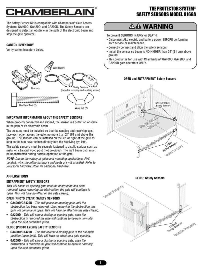
Entrapment Safety Sensors
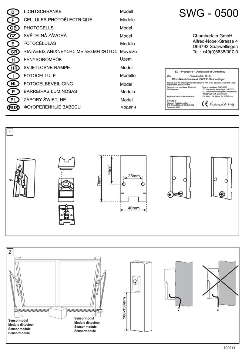
• Connect ENTRAPMENT safety sensors wires to P8 terminal.
NOTE: This will pause an opening gate until the obstruction has been
removed. Upon removing the obstruction, the gate will continue to
open. This will have no effect on the gate closing.
Open Safety Sensors
• Connect OPEN safety sensor wires to P7 terminal.
NOTE: This will pause an opening gate until the obstruction has been
removed. Upon removing the obstruction, the gate will continue to
open. This will have no effect on the gate closing.
Close Safety Sensors
• Connect CLOSE safety sensors wires to P9 terminal.
NOTE: This will reverse a closing gate to the full open position (open
limit). This will have no effect on a gate opening.
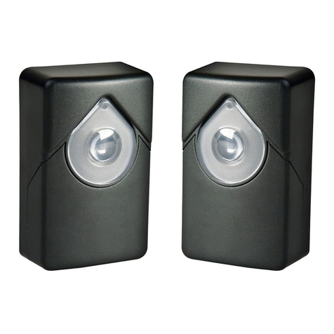
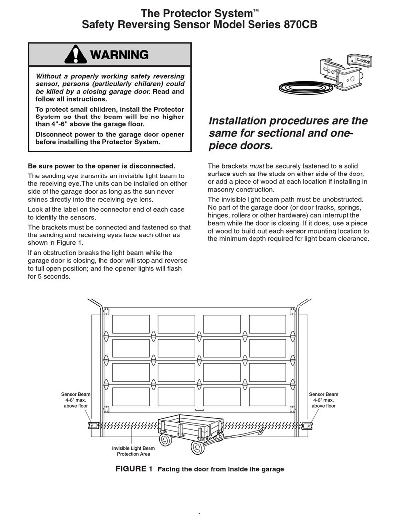
ALIGN SAFETY SENSORS
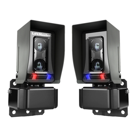
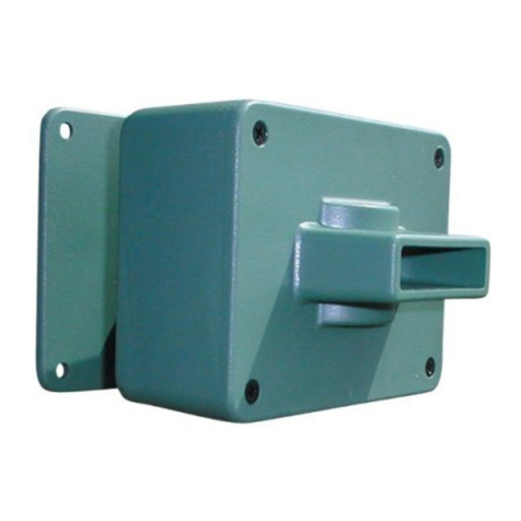
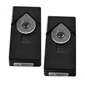
• Plug in the operator. The indicator lights in both the sending and
receiving eyes will glow steadily if wiring connections and alignment
are correct.
The sending eye indicator light will glow regardless of alignment or
obstruction. If the indicator light in the receiving eye is off, dim, or
flickering (and the invisible light beam path is not obstructed), alignment
is required.
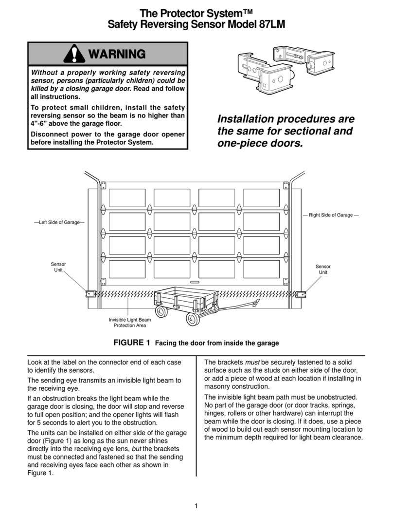
• Loosen the sending eye wing nut and readjust, aiming directly at
the receiving eye. Lock in place.
• Loosen the receiving eye wing nut and adjust sensor until it
receives the sender’s beam. When the green indicator light glows
steadily, tighten the wing nut.
NOTE: When properly aligned, the indicator lights in both the sending
and receiving eyes will glow steadily.
TEST THE SYSTEM
1. Press the remote control button to open the gate.
2. Place an obstruction in the path of the close or entrapment sensor.
Verify the gate stops until the obstruction is removed.
3. Press the remote control button to close the gate.
The gate should stop. The gate operator will not function from a remote
if the indicator light in either sensor is off (alerting you to the fact that
the sensor is misaligned or obstructed). If the system continues to fail
the test, call for a trained gate systems technician.
Verify all other safety devices operate correctly.
TROUBLESHOOTING
If the sending or receiving LEDs do not light up after installation, please
check the following:
• Power supply to the operator. Make sure the operator is not in stand-
by mode. Power is removed from the safety circuits in this mode.
Press the reset button to wake up the operator. Circuits should be
powered and safety circuits auto-learned.
• Short-circuit in the black/white cable. This can happen beneath
clamps or at the connecting terminals.
• Incorrect wire connections between the sensor and operator. • Interruption to the power supply circuit (broken wire).
If both sensors are flashing:
• Align sensors.
• Remove obstruction.
• Erase the programming for the safety sensors - remove safety sensor.
Press learn limits button then press reset button.
