manuals.online logo
Brands
  1. Home
  2. •
  3. Brands
  4. •
  5. Chamberlain
  6. •
  7. Accessories
  8. •
  9. Chamberlain DH Quick start guide

Chamberlain DH Quick start guide

This manual suits for next models

4

Other Chamberlain Accessories manuals

Chamberlain 836LM User manual

Chamberlain

Chamberlain 836LM User manual

Chamberlain Protector System 770E User manual

Chamberlain

Chamberlain Protector System 770E User manual

Chamberlain DH Installation and operating instructions

Chamberlain

Chamberlain DH Installation and operating instructions

Chamberlain PROFESSIONAL TCLS1E User manual

Chamberlain

Chamberlain PROFESSIONAL TCLS1E User manual

Chamberlain 771ANZ User manual

Chamberlain

Chamberlain 771ANZ User manual

Chamberlain 50-HERK2 User manual

Chamberlain

Chamberlain 50-HERK2 User manual

Chamberlain 870CB Series User manual

Chamberlain

Chamberlain 870CB Series User manual

Chamberlain Protector 87LM User manual

Chamberlain

Chamberlain Protector 87LM User manual

Chamberlain 41C4672 Guide

Chamberlain

Chamberlain 41C4672 Guide

Chamberlain THE PROTECTOR SYSTEM 916GA User manual

Chamberlain

Chamberlain THE PROTECTOR SYSTEM 916GA User manual

Chamberlain LMRRU User manual

Chamberlain

Chamberlain LMRRU User manual

Chamberlain The Protector G70 User manual

Chamberlain

Chamberlain The Protector G70 User manual

Chamberlain SWG-0500 User manual

Chamberlain

Chamberlain SWG-0500 User manual

Chamberlain PIR2300R User manual

Chamberlain

Chamberlain PIR2300R User manual

Chamberlain LMTBUL User manual

Chamberlain

Chamberlain LMTBUL User manual

Chamberlain CPS-UN4 User manual

Chamberlain

Chamberlain CPS-UN4 User manual

Chamberlain 771E User manual

Chamberlain

Chamberlain 771E User manual

Chamberlain 915GA User manual

Chamberlain

Chamberlain 915GA User manual
Chamberlain Secure Home SH-9525AU User manual
Chamberlain

Chamberlain Secure Home SH-9525AU User manual

Chamberlain Protector System 770EML User manual

Chamberlain

Chamberlain Protector System 770EML User manual

Chamberlain 916GA User manual

Chamberlain

Chamberlain 916GA User manual

Chamberlain PIRV400R User manual

Chamberlain

Chamberlain PIRV400R User manual

Chamberlain LMTBU User manual

Chamberlain

Chamberlain LMTBU User manual

Chamberlain 821LM-SENSOR User manual

Chamberlain

Chamberlain 821LM-SENSOR User manual
Popular Accessories manuals by other brands

Quincy lab 140AE-1 operating manual

Quincy lab

Quincy lab 140AE-1 operating manual

HomePro ZIR000 user manual

HomePro

HomePro ZIR000 user manual

DOL 20SCR Technical user guide

DOL

DOL 20SCR Technical user guide

RAB Smart Task installation manual

RAB

RAB Smart Task installation manual

Kemppi KMS 300 quick guide

Kemppi

Kemppi KMS 300 quick guide

Stearns 57,500 Series Installation and service instructions

Stearns

Stearns 57,500 Series Installation and service instructions

iGuzzini TWILIGHT COPENAGHEN manual

iGuzzini

iGuzzini TWILIGHT COPENAGHEN manual

Adelaide Annexe & Canvas Avan Deluxe installation guide

Adelaide Annexe & Canvas

Adelaide Annexe & Canvas Avan Deluxe installation guide

OHAUS 5000 instruction manual

OHAUS

OHAUS 5000 instruction manual

HOME8 WLS1300 quick start guide

HOME8

HOME8 WLS1300 quick start guide

MAXBOTIX MaxSonar quick start guide

MAXBOTIX

MAXBOTIX MaxSonar quick start guide

ioSmart iSmart56 Installation and user guide

ioSmart

ioSmart iSmart56 Installation and user guide

Focusrite Scarlett 18i8 user guide

Focusrite

Focusrite Scarlett 18i8 user guide

Velleman ED38105 user manual

Velleman

Velleman ED38105 user manual

JumpSport SkyBounce user manual

JumpSport

JumpSport SkyBounce user manual

Prima-Temp PRIYA Instructions for use

Prima-Temp

Prima-Temp PRIYA Instructions for use

Tefcold BC85I-BC85I W user manual

Tefcold

Tefcold BC85I-BC85I W user manual

Vaisala WMS302 user guide

Vaisala

Vaisala WMS302 user guide

manuals.online logo
manuals.online logoBrands
  • About & Mission
  • Contact us
  • Privacy Policy
  • Terms and Conditions

Copyright 2025 Manuals.Online. All Rights Reserved.

APPLICATION REQUIREMENTS
This wiring modification is available to models DJ and DH/J
Standard-Duty operators with 24Vac control circuits and “D1”
type wiring.
NOTE: If C2 or B2 wiring is desired refer to conversion
instructions on pages 2 and 3.
FUNCTIONS
This modification stops the operator when extra tension is
sensed on the door from the mechanical door lock, obstruction
or extensive binding.
OPERATION
When the operator senses extra tension when closing, the Lock
Sensor will stop the operator. Press close button and run until
the operator shuts off (to unlock door when load removed).
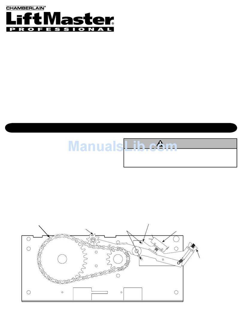
LOCK SENSOR (D1 WIRING)
WIRING DIAGRAM & INSTRUCTIONS
Model: DH, DJ and DH/J
ADJUSTMENT
FINE ADJUSTMENT
• To increase opening force, tighten wing nut.
• To decrease opening force, loosen wing nut.
COURSE ADJUSTMENT (if required)
1. Release spring pressure on pivot arm.
2. Loosen but do not remove mounting screws (2).
3. Fully tension final reduction chain and rotate Lock Sensor
until switch is in activation mode.
4. Tighten mounting screws (2) to secure Lock Sensor position.
5. Repeat fine adjustments.
Lock Sensor
Assembly
To adjust opening force
tighten or loosen wing
nut accordingly
Chain Idler Sprocket
must engage top side
of reduction chain
Final Reduction
Chain Lock Sensor Switch
(held to normally closed)
Mounting
Screws
To avoid SERIOUS PERSONAL INJURY or DEATH from
electrocution, disconnect electric power to operator BEFORE
adjusting Lock Sensor.
FIGURE 1
2
1PH SCHEMATIC DIAGRAM 1827-1
ELECTRICAL BOX
END VIEW
LIMIT
NUT
SAFETY LIMIT SW.
AUXILIARY CLOSE
CLOSE
LIMIT SW.
OPEN
LIMIT SW.
AUXILIARY OPEN
LIMIT SW.
DEPRESS
PLATE
OVERLOAD
(SEE NOTE 3)
MOTOR OVERLOAD
(SEE NOTE 3)
(SEE NOTE 2)
NOTES:
1) TO REVERSE MOTOR DIRECTION: INTERCHANGE PURPLE &
GRAY MOTOR LEADS AT CONTACTOR 1 & 3.
2) TRANSFORMER PRIMARY & RELAY VOLTAGE SAME AS LINE VOLTAGE.
3) THREE PHASE UNITS MAY BE EQUIPPED WITH AN INTERNAL PILOT DUTY
THERMAL OVERLOAD DEVICE, OR AN EXTERNAL LINE MONITORING DEVICE.
(WHEN PRESENT)
230V BRAKE
2
3
YEL
PUR
GY 1
6
9
BL/BK
BL/BK
4
7
(WHEN PRESENT)
230V BRAKE
2
3
YEL
PUR
GY 1
6
9
BL/BK
BL/BK
4
7
85
208/230 VOLT - 3 PHASE
MOTOR CONNECTION
460 VOLT - 3 PHASE
MOTOR CONNECTION
(WHEN PRESENT)
575V BRAKE
3
BL/BK
BL/BK
1
2
YEL
PUR
GY
575 VOLT - 3 PHASE
MOTOR CONNECTION
(WHEN PRESENT)
230V BRAKE
2
3
YEL
PUR
GY 1
6
9
BL/BK
BL/BK
4
7
(WHEN PRESENT)
230V BRAKE
2
3
YEL
PUR
GY 1
6
9
BL/BK
BL/BK
4
7
85
MOTOR CONNECTION
460 VOLT - 3 PHASE
MOTOR CONNECTION
(WHEN PRESENT)
575V BRAKE
3
BL/BK
BL/BK
1
2
YEL
PUR
GY
575 VOLT - 3 PHASE
MOTOR CONNECTION
(WHEN PRESENT)
230V BRAKE
2
3
YEL
PUR
GY 1
6
9
BL/BK
BL/BK
4
7
(WHEN PRESENT)
230V BRAKE
2
3
YEL
PUR
GY 1
6
9
BL/BK
BL/BK
4
7
85
MOTOR CONNECTION
460 VOLT - 3 PHASE
MOTOR CONNECTION
(WHEN PRESENT)
575V BRAKE
3
BL/BK
BL/BK
1
2
YEL
PUR
GY
575 VOLT - 3 PHASE
MOTOR CONNECTION
(WHEN PRESENT)
230V BRAKE
2
3
YEL
PUR
GY 1
6
9
BL/BK
BL/BK
4
7
(WHEN PRESENT)
230V BRAKE
2
3
YEL
PUR
GY 1
6
9
BL/BK
BL/BK
4
7
85
MOTOR CONNECTION
460 VOLT - 3 PHASE
MOTOR CONNECTION
(WHEN PRESENT)
575V BRAKE
3
BL/BK
BL/BK
1
2
YEL
PUR
GY
575 VOLT - 3 PHASE
MOTOR CONNECTION
OVERLOAD
(SEE NOTE 3)
*OVERLOAD
(SEE NOTE 3)
*OVERLOAD
(SEE NOTE 3)
*
MOTOR O/L LEAD COLOR BROWN
*
BK
BK
85858585
BK
BK
BK
BK
C2 WIRING CONVERSION
1. Move Orange wire from terminal 7 to terminal 3.
2. Move Yellow wire from terminal 1 to terminal 3.
NOTE: Be sure to supply a STOP button after conversion.
B2 WIRING CONVERSION
1. Move Orange wire from terminal 7 to terminal 3.
2. Move Yellow wire from terminal 1 to terminal 3.
3. Move Red wire from terminal 2 to terminal 3.
NOTE: Be sure to supply a STOP button and safety edge
after conversion.
3
3PH SCHEMATIC DIAGRAM 1827-3
ELECTRICAL BOX
END VIEW
LIMIT
NUT
SAFETY LIMIT SW.
AUXILIARY CLOSE
CLOSE
LIMIT SW.
OPEN
LIMIT SW.
AUXILIARY OPEN
LIMIT SW.
DEPRESS
PLATE
OVERLOAD
(SEE NOTE 3)
MOTOR OVERLOAD
(SEE NOTE 3)
(SEE NOTE 2)
NOTES:
1) TO REVERSE MOTOR DIRECTION: INTERCHANGE PURPLE &
GRAY MOTOR LEADS AT CONTACTOR 1 & 3.
2) TRANSFORMER PRIMARY & RELAY VOLTAGE SAME AS LINE VOLTAGE.
3) THREE PHASE UNITS MAY BE EQUIPPED WITH AN INTERNAL PILOT DUTY
THERMAL OVERLOAD DEVICE, OR AN EXTERNAL LINE MONITORING DEVICE.
(WHEN PRESENT)
230V BRAKE
2
3
YEL
PUR
GY 1
6
9
BL/BK
BL/BK
4
7
(WHEN PRESENT)
230V BRAKE
2
3
YEL
PUR
GY 1
6
9
BL/BK
BL/BK
4
7
85
208/230 VOLT - 3 PHASE
MOTOR CONNECTION
460 VOLT - 3 PHASE
MOTOR CONNECTION
(WHEN PRESENT)
575V BRAKE
3
BL/BK
BL/BK
1
2
YEL
PUR
GY
575 VOLT - 3 PHASE
MOTOR CONNECTION
(WHEN PRESENT)
230V BRAKE
2
3
YEL
PUR
GY 1
6
9
BL/BK
BL/BK
4
7
(WHEN PRESENT)
230V BRAKE
2
3
YEL
PUR
GY 1
6
9
BL/BK
BL/BK
4
7
85
MOTOR CONNECTION
460 VOLT - 3 PHASE
MOTOR CONNECTION
(WHEN PRESENT)
575V BRAKE
3
BL/BK
BL/BK
1
2
YEL
PUR
GY
575 VOLT - 3 PHASE
MOTOR CONNECTION
(WHEN PRESENT)
230V BRAKE
2
3
YEL
PUR
GY 1
6
9
BL/BK
BL/BK
4
7
(WHEN PRESENT)
230V BRAKE
2
3
YEL
PUR
GY 1
6
9
BL/BK
BL/BK
4
7
85
MOTOR CONNECTION
460 VOLT - 3 PHASE
MOTOR CONNECTION
(WHEN PRESENT)
575V BRAKE
3
BL/BK
BL/BK
1
2
YEL
PUR
GY
575 VOLT - 3 PHASE
MOTOR CONNECTION
(WHEN PRESENT)
230V BRAKE
2
3
YEL
PUR
GY 1
6
9
BL/BK
BL/BK
4
7
(WHEN PRESENT)
230V BRAKE
2
3
YEL
PUR
GY 1
6
9
BL/BK
BL/BK
4
7
85
MOTOR CONNECTION
460 VOLT - 3 PHASE
MOTOR CONNECTION
(WHEN PRESENT)
575V BRAKE
3
BL/BK
BL/BK
1
2
YEL
PUR
GY
575 VOLT - 3 PHASE
MOTOR CONNECTION
OVERLOAD
(SEE NOTE 3)
*OVERLOAD
(SEE NOTE 3)
*OVERLOAD
(SEE NOTE 3)
*
MOTOR O/L LEAD COLOR BROWN
*
BK
BK
85858585
BK
BK
BK
BK
C2 WIRING CONVERSION
1. Move Orange wire from terminal 7 to terminal 3.
2. Move Yellow wire from terminal 1 to terminal 3.
NOTE: Be sure to supply a STOP button after conversion.
B2 WIRING CONVERSION
1. Move Orange wire from terminal 7 to terminal 3.
2. Move Yellow wire from terminal 1 to terminal 3.
3. Move Red wire from terminal 2 to terminal 3.
NOTE: Be sure to supply a STOP button and safety edge
after conversion.
© 2008, The Chamberlain Group, Inc.
01-16492C All Rights Reserved
CONTROL CONNECTION DIAGRAM
3 BUTTON STATION OR 3 POSITION KEYSWITCH WITH SPRING RETURN TO CENTER AND STOP BUTTON
2 OR MORE KEY LOCKOUT
1 2 3 4
Stop
Close
Open
Stop
Close
Open
1 2 3 4
Stop
Close
Open
2 BUTTON STATION OR 3 POSITION KEYSWITCH WITH SPRING RETURN TO CENTER
STANDARD
1 2 4
Close
Open
ALL CONTROL WIRING TYPES
2 OR MORE
1 2 4
Close
Open
Close
Open
Open / Close
37
1 BUTTON STATION OR
ANY AUXILIARY DEVICE
EXTERNAL INTERLOCKSENSING DEVICE TO REVERSE OR STOP
310
4545
Remove Jumper
When Interlock is Used
One 2 or More
STANDARD
1 2 3 4
Stop
Close
Open
IMPORTANT NOTES:
1. The 3-Button Control Station provided must be connected for operation.
2. If a STOP button is not used, a jumper must be placed between
terminals 3 and 4.
3. Auxiliary control equipment may be any normally open two wire device
such as pullswitch, single button control station, loop detector, card key or such device.
Keyswitch
Sensing Device
ALL CONTROL WIRING TYPES
B2 OR T1
WIRING TYPES ONLY
ALL CONTROL WIRING TYPESALL CONTROL WIRING TYPES
ALL CONTROL WIRING TYPES
ALL CONTROL WIRING TYPESALL CONTROL WIRING TYPES
ATTENTION ELECTRICIAN:
USE 16 GAUGE OR HEAVIER WIRE
FOR ALL CONTROL CIRCUIT WIRING.
SEE NOTE #2SEE NOTE #2 SEE NOTES
#2 AND #3