9
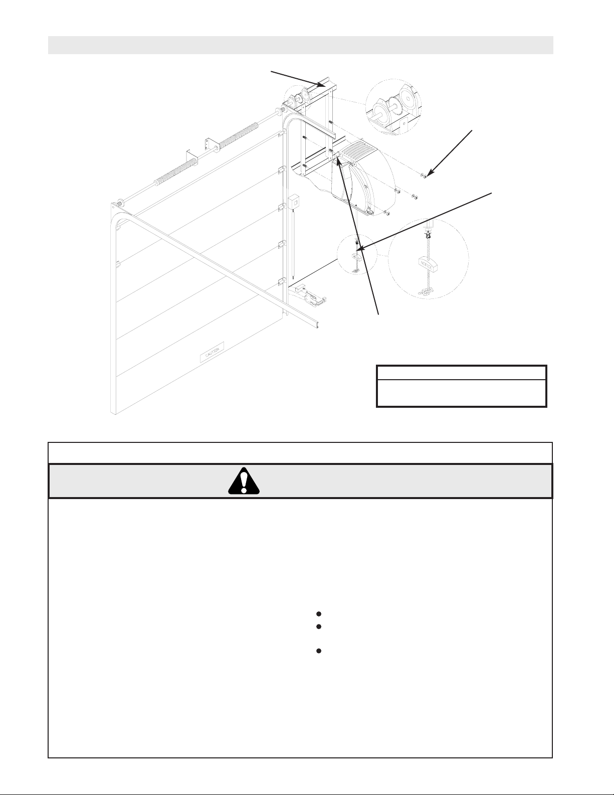
CABLE TENSION SENSOR ASSEMBLY AND INSTALLATION INSTRUCTIONS
NOTE: Left hand assembly shown, for right hand assembly,
orientation will be opposite.
1. Introduce cable slack on the side of the door where the
CTS will be installed (Left side of door from inside of garage
looking out for left hand unit and right side of door for right
hand unit).
2. Use a 5/32” alan wrench to remove the socket head cap
screw from the pivot arm assembly. Place the pivot arm
assembly around the torsion shaft as shown, reinstall the
socket head cap screw and tighten.
3. Slide the pivot arm towards the cable drum and feed the
door cable over the front side of the pivot arm roller. Place
the assembly against the side of the drum.
4. Use a 3/16” alan wrench to remove the socket head cap
screws from the split shaft collar. Place the collar
around the torsion shaft and reinstall screws. Do not tighten.
5. Slide the collar towards the pivot arm and touch the side of
the pivot arm lightly. Tighten the screws in the collar.
NOTE: Make sure that the pivot arm is free to rotate after
the collar is tightened. The collar must hold the pivot
arm as close as possible to the cable drum, however, not
so tightly that the arm is not free to rotate on the torsion
shaft.
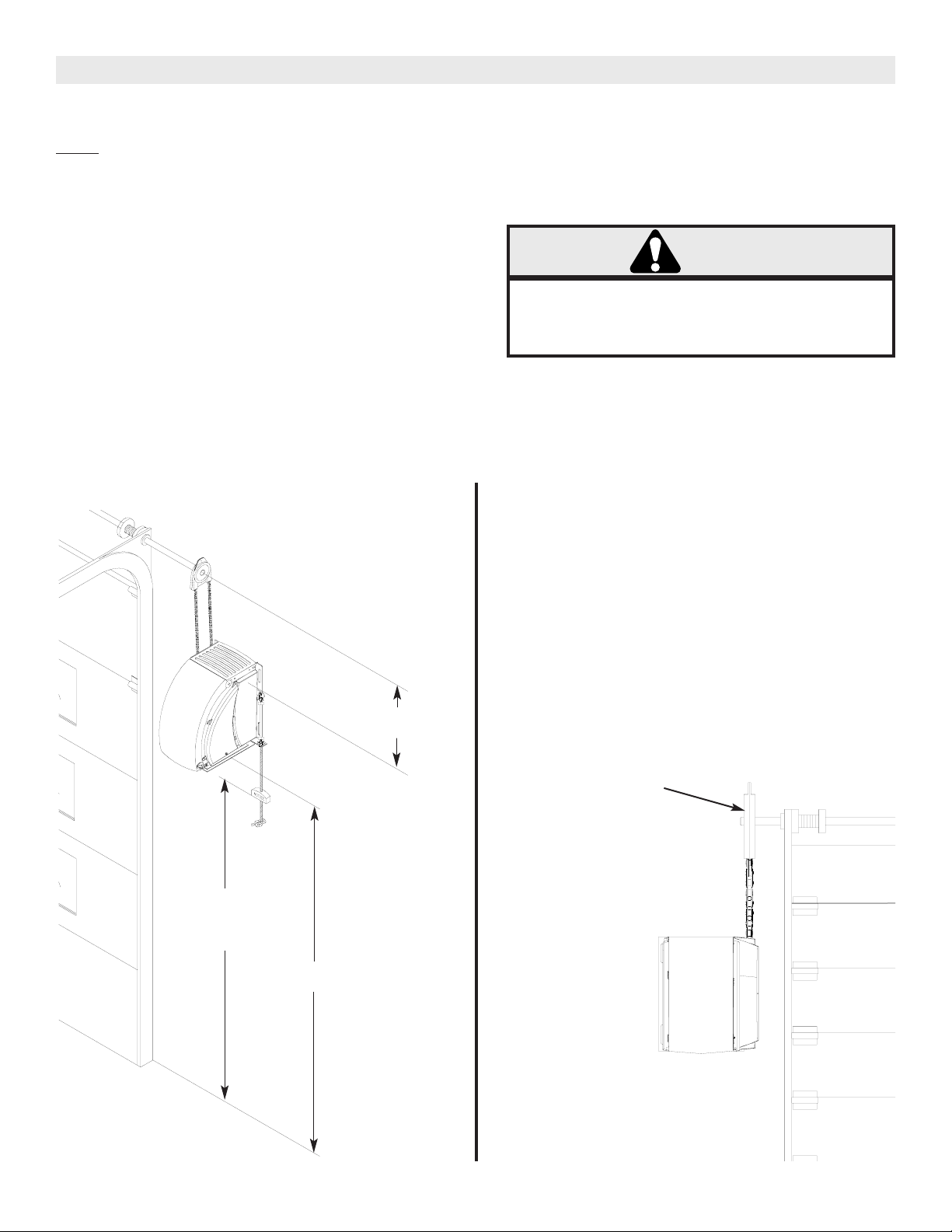
6. Place the CTS assembly into position. Make sure
that the roll pin on the pivot arm extends through the angled
slot on the CTS. Rotate pivot arm down towards header side
of the angled slot. With the roller on the CTS over the front
side of the door cable and the assembly in position, mark the
location of the 5 CTS assembly mounting holes and then
remove the assembly.
NOTE: Measure the distance from the center of the torsion
shaft to the header where the CTS will be mounted. The
optimum distance is 2-3/4”. If your measurement is
more than the 2-3/4” the CTS must have a backer
installed to make up the difference.
EXAMPLE: If you measure 2-7/8” you will need a 1/8” thick
backer. If you measure 3” you will need to install a 1/4”
thick backer, etc. Repeat step 6 if a backer was installed.
7. Drill pilot holes for the 5 CTS lag bolt mounting screws.
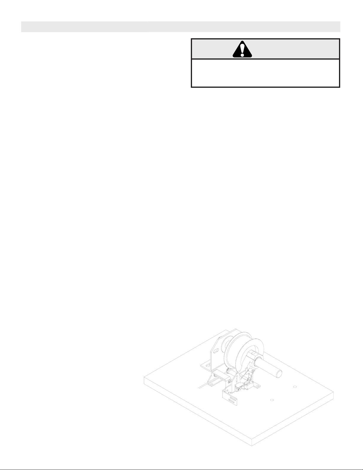
To prevent possible SERIOUS INJURY OR DEATH,
SECURELY mount the operator for proper operation
of the Cable Tension Sensor Assembly.
WARNING
8. Reinstall the CTS and attach to the header using the 1/4” x
1” lag screw provided.
NOTE: If it is necessary to use longer screws, due to
backer or other conditions, to securely fasten the
assembly, obtain them at local hardware store. 1/4”is
the required size.
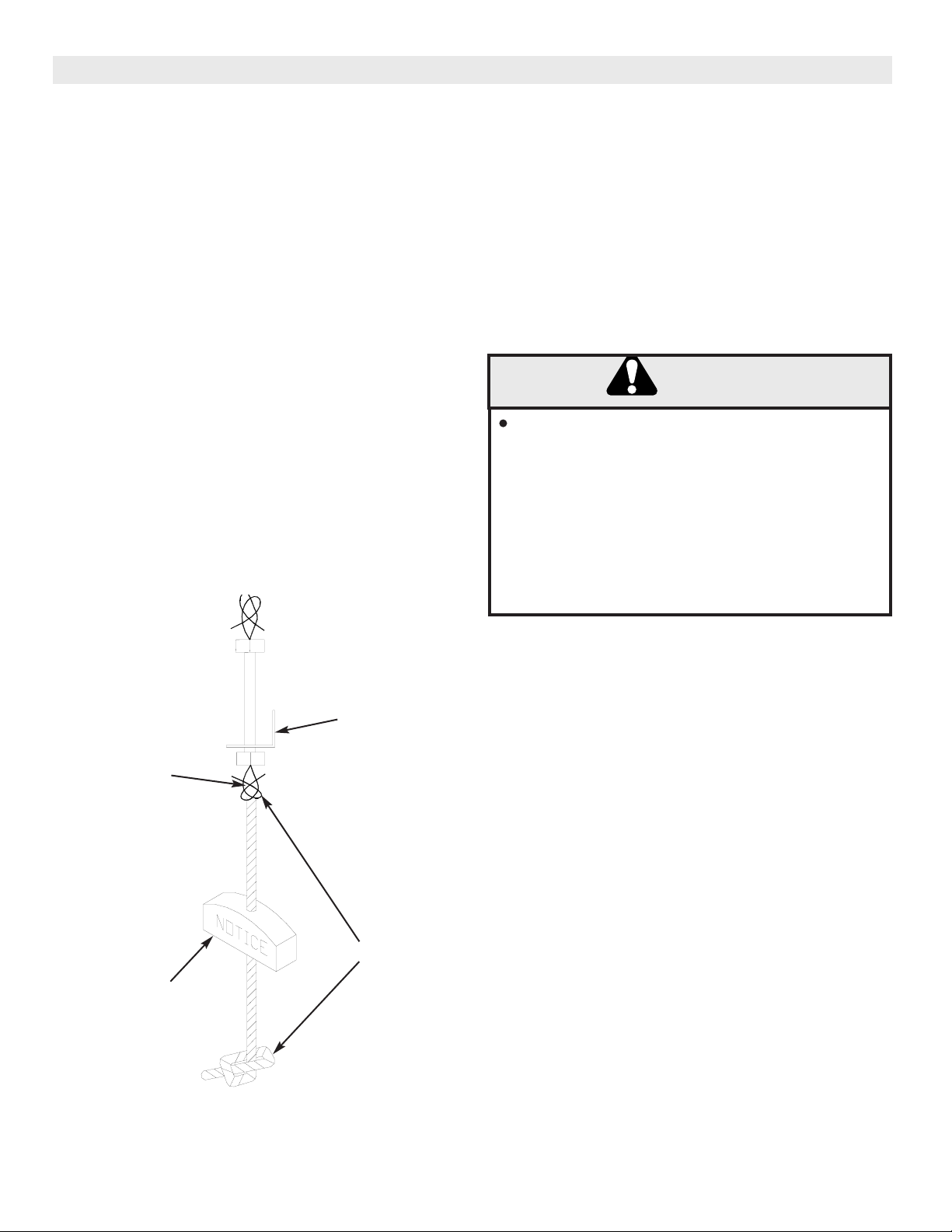
9. Rotate the pivot arm out away from the header. Maintain the
pivot arm in this position. Rotate the torsion spring counter
clockwise and place the end of the spring beneath the pivot
arm roll pin.
NOTE: Make sure that the other leg of the spring hooks
onto the tab extending from the CTS as shown. (Had this
been a right hand assembly, the spring would have been
rotated clockwise as viewed.)
10. You may now remove the slack that was introduced into the
door cable.
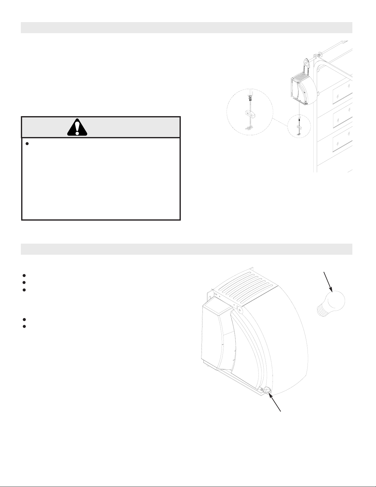
11. Attach the door stopper bracket to the CTS by removing
the 2 mounting screws with a 5/16” wrench. The bracket can
be mounted with the long leg or the short leg attached to the
CTS. This will depend on the distance from the CTS to the
top of the top door section. Tighten the 2 mounting screws.
Apply the self adhesive bumpers supplied to the bottom side
of the door stopper bracket.
12. Try to raise the door manually and check to make sure that
the door stopper bracket contacts the top of the top door
section when this is done. Loosen, adjust and relighten as
needed to accomplish this.
13. Wire the common and the normally open contacts of the
CTS switch in series with one of the wires from the receiving
photo eye. Flag style terminals have been provided to make
your connections. Refer to the wiring diagram in the back of
the owner’s manual.
CABLE TENSION
SENSOR ASSEMBLY
(CTS)