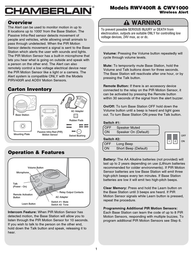
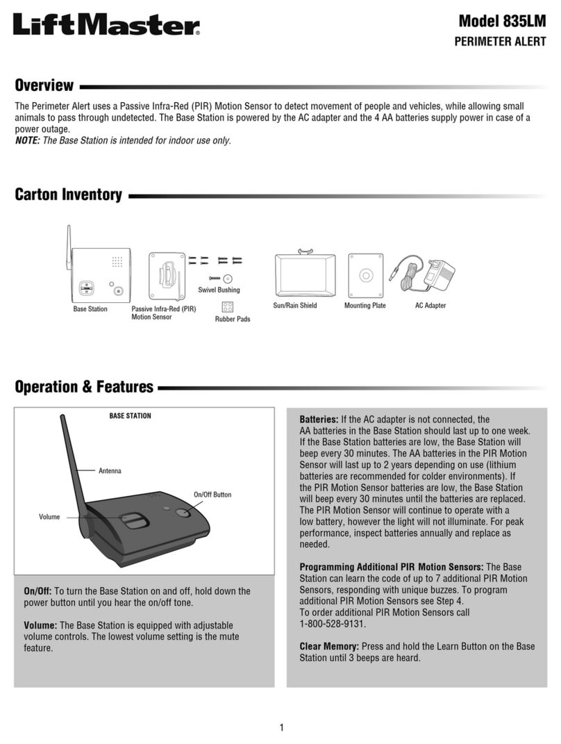
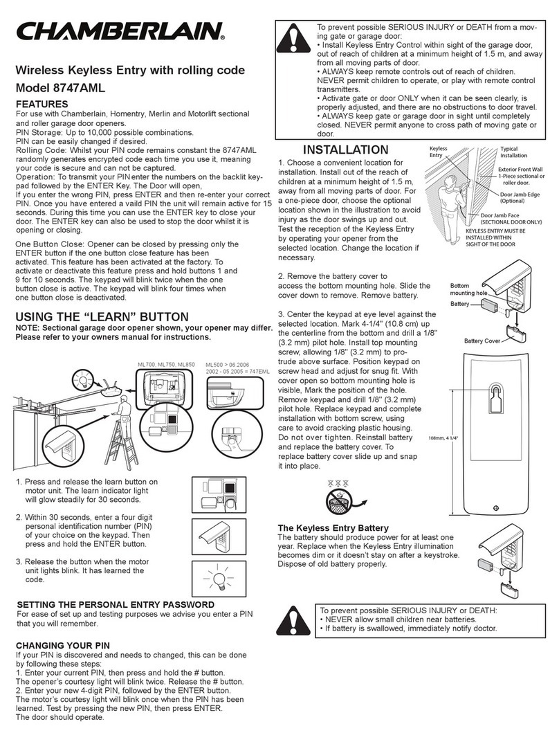
Chamberlain K74-18655 User manual

CARTON INVENTORY
• Alarm with wire harness (1)
• Extra blue wire stripped on both sides (connects J1-3 to
J1-15) (1)
• Wire ties (4)
• Flange (41-G0538) (1)
TOOLS NEEDED
• Pliers
• #2 Phillips Head screwdriver
• 1/8" flat Phillips Head screwdriver
• Diagonal wire cutters
• Wire strippers
To reduce the risk of INJURY or DEATH:
• Disconnect all power BEFORE installing or servicing operator.
• See manual prior to servicing regarding maintenance and
required safety testing.
DC Alarm Kit
K74-18655 for SW420, SW470, and SW490 Operators
WARNING: This product can expose you to chemicals
including lead, which are known to the State of
California to cause cancer or birth defects or other
reproductive harm. For more information go to
www.P65Warnings.ca.gov.
Components covered
with heat shrink
Removable
connector
AC ALARM
DC ALARM
1234567891011 12 13 14 15 16
1234567891011 12 13 14 15 16
Alarm
Plastic nut
Flange
Regulator
covered with
heat shrink
Operator chassis
Wire harness
Old alarm
Flange
Operator chassis
Plastic nut
LAYOUT FOR SW470 SHOWN
Main board
LAYOUT FOR SW470 SHOWN
Main board
J1 TERMINAL BLOCK
Red wire (+) from alarm
Black wire (-) from alarm
J1 TERMINAL BLOCK
Red wire (+) from alarm
Black wire (-) from alarm
REMOVE THE EXISTING DC ALARM
1. Disconnect power from the operator.
2. Disconnect the wire harness from the main board connections
J1-16 and J1-12 (Figure 1).
NOTE: The J1 terminal block can be removed from the main
board to aid in wiring. If you remove the terminal block, make
sure to replace it securely on the main board.
3. Remove the existing alarm and wire harness (Figure 2).
FIGURE 1
FIGURE 2
Existing alarm
Flange
Operator chassis
Plastic nut
For reference only. Your equipment may look different.

2
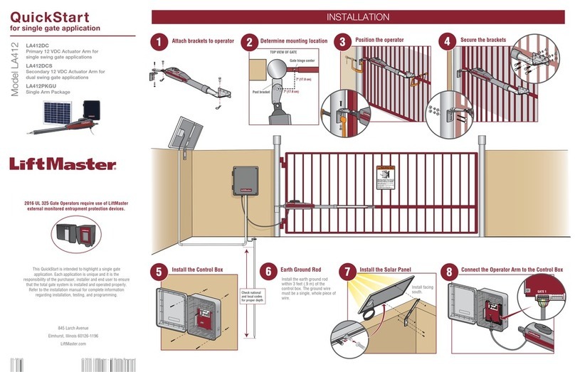
INSTALL THE NEW DC ALARM
1. Insert the provided alarm flange onto the
chassis using the mounting holes that held
the old alarm.
2. Mount the alarm in the flange (Figure 3).
a. Remove the plastic nut from the alarm.
b. Insert the alarm through the flange.
c. Secure the alarm to the flange with the
plastic nut.
3. Use a provided wire tie to secure the wires
from the alarm to the body of the alarm as
shown to prevent the wires from being
tangled in the sprocket.
4. Route the wire harness to the main board
following the same path as the old harness.
Connect the red wire to J1-16, and the black
wire to J1-12. Polarity is important (see
illustration). If NOT connected with correct
polarity, the alarm will be damaged (Figure
4).
5. Use the wire ties provided to secure the
harness.
6. Connect the provided blue wire between J1-3
and J1-15 (Figure 4).
7. Restore power to the operator.
P1 P2 P3 P4 R1 R2 R3 R4 B
1234567891011 12 13 14 15 16
Red Wire
Black Wire
TERMINAL BLOCK LOCATED ON THE CHASSIS
LAYOUT FOR SW470 SHOWN
Wire Harness to Alarm
Main board
J1 TERMINAL BLOCK
Red wire (+) from alarm
Black wire (-) from alarm
Blue wire
Alarm
Wire tie
Plastic nut Flange
Operator chassis
Wire harness
FIGURE 3
FIGURE 4

3
SINGLE PHASE WIRING DIAGRAM SW420 SINGLE PHASE WIRING DIAGRAM SW470
R2
R1 R2 R3 R4
R3
R4
J4
1
2
+
-
J2-3
J2-4
J2-5
J2-6
J2-7
J2-1
J2-8
J2-2
J2-9
J2-10
J2-11
J1-1
J1-2
J1-3
J1-4
J1-5
J1-6
J1-7
J1-8
J1-9
J1-10
J1-11
J1-12
J1-13
J1-14
J1-15
J1-16
24VAC-IN
24VAC-COMMON
SOFT OPEN
NC
"B" LIMIT
CONTACTOR B
"A" LIMIT
CONTACTOR A
RPM-IN
RPM-SUPPLY
RPM GND
RADIO COMMAND
SHADOW
+24 VDC
CLOSE
STOP
SOFT OPEN
HARD OPEN
INT. LOOP
OBS. OPEN
OBS. CLOSE
24VAC-COMMON
DC-GND
LOCK 1
LOCK 2
ALARM 1
ALARM 1
J2 PLUG
J2 PLUG
NC
MOV
MOV
L/S B
COM
NC
L/S A
COM
1-PHASE
POWER IN
White
White
White
BUTT
SPLICE
Black
Black
Green Green
Gray
Yellow
Yellow
Yellow
Yellow
Green/White
Purple/White
Purple/White
Red
Red
Red
Red
White
Orange
Orange
Yellow
Orange/Black
Black
Black
Blue
Brown Brown
Brown
Brown
Brown
Blue
Black
GROUND
24V
SEC
GL CONTROL BOARD
RPM
SENSOR
ALARM ASSY
76-G0564
OPTION
24 VAC RADIO
SIGNAL
SEE NOTE 2
NOTE 1
MOTOR
SWITCH
CAPACITOR
SEE NOTE 1
PRIMARY
DUAL GATE
NOTES:
1) TRANSFORMER PRIMARY VOLTAGE SAME AS OPERATOR LINE VOLTAGE
24V SCONDARY
60VA.
2)
TERMINAL DESIGNATIONS SHOWN FOR 115V ONLY.
LEGEND
PERMANENT TERMINAL
J1 TERMINAL BLOCK
TERMINAL BLOCK
R2
J1-6
3R3
1 2
J4
R1 R2 R3 R4 3 5 5 8 9 10 11 12
R4
J1-11
P/N 90-G0601
J2-3
J2-4
J2-5
J2-6
J2-7
J2-1
J2-8
J2-2
J2-9
J2-10
J2-11
J1-1
J1-2
J1-3
J1-4
J1-5
J1-6
J1-7
J1-8
J1-9
J1-10
J1-11
J1-12
J1-13
J1-14
J1-15
J1-16
24VAC-IN
24VAC-COMMON
SOFT OPEN
NC
"B" LIMIT
CONTACTOR B
"A" LIMIT
CONTACTOR A
RPM-IN
RPM-SUPPLY
RPM GND
RADIO COMMAND
SHADOW
+24 VDC
CLOSE
STOP
SOFT OPEN
HARD OPEN
INT. LOOP
OBS. OPEN
OBS. CLOSE
24VAC-COMMON
DC-GND
LOCK 1
LOCK 1
ALARM 1
ALARM 1
J2 PLUG
J1 PLUG
L1
L2
C
C
NC C NC
NC
NC
L/S B
O/L
L/S A
NC C
C
NO
C NO
C NO
NO
LEGEND
PERMANENT TERMINAL
J1 TERMINAL BLOCK
TERMINAL BLOCK
115 VAC
1-PHASE
White
White
White
BUTT
SPLICE
Black
GreenGreen
Gray
Gray
Gray
Gray
Yellow
Yellow
Yellow
Yellow
Yellow
Yellow
Green/White
Green/White
Green/White
Purple/White
Purple/White
Red
Red
Red
Red
Red
+
Red -
Black
White
White
Orange
Orange
Orange
Orange
Yellow
Black
Red
Red
Orange/Black
Yellow/Black
Black
Black
Blue
Blue
Brown
Brown
Brown
Brown
Blue
Black
Black Black
GND
24VAC SEC
GL CONTROL BOARD
RPM
SENSOR
ALARM ASSY
76-G0564
OPTION
24 VAC RADIO
SIGNAL STOP INTERRUPT
LOOP
ENTRAPMENT
OPEN
ENTRAPMENT
CLOSE
TO
PRIMARY/SECONDARY
UNIT
SEE NOTE 2 SEE NOTE 4
MOTOR
RESISTOR
CAPACITOR
CLOSE B
OPEN A
SEE NOTE 1
PRIMARY
SEE NOTE 2
DUAL GATE
SEE NOTE 3
SAFETY
LOOP
HARNESS
(10-PIN)
OPEN LOOP
HARNESS
(10-PIN)
FROM
OPEN
LOOP
FROM
SAFETY
LOOP
OPTIONAL WIRE
FIELD WIRING
HARNESS
NOTES:
1) TRANSFORMER PRIMARY VOLTAGE SAME AS OPERATOR LINE VOLTAGE
24V SCONDARY 15VA.
2) TERMINAL DESIGNATIONS SHOWN FOR 115V ONLY.
3) OPTIONAL WIRE HARNESS.
4) CONNECTED INTERNALLY ON GL PC BOARD.

4
3 PHASE WIRING DIAGRAM SW490
R2
R3
R4
R4R3R2R1
R1
R1
J4
1
2
-
+
J2-3
J2-4
J2-5
J2-6
J2-7
J2-1
J2-8
J2-2
J2-9
J2-10
J2-11
J1-1
J1-2
J1-3
J1-4
J1-5
J1-6
J1-7
J1-8
J1-9
J1-10
J1-11
J1-12
J1-13
J1-14
J1-15
J1-16
24VAC-IN
24VAC-COMMON
SOFT OPEN
NC
"B" LIMIT
CONTACTOR B
"A" LIMIT
CONTACTOR A
RPM-IN
RPM-SUPPLY
RPM GND
RADIO COMMAND
SHADOW
+24 VDC
CLOSE
STOP
SOFT OPEN
HARD OPEN
INT. LOOP
OBS. OPEN
OBS. CLOSE
24VAC-COMMON
DC-GND
LOCK 1
LOCK 2
ALARM 1
ALARM 1
J2 PLUG
XFMR
R1XFMR
R1
XFMR
R1XFMR
J2 PLUG
MOV
MOV
NC
L/S B
COM
NC
L/S A
COM
White
White
White
White
Green Green
Green
Green
Green
Green/Yellow
Yellow
Yellow
Green/White
Purple/White
Purple/White
Red
Red Red
Red
Red
Red
Red
White
Orange
Orange
Orange
Orange
Yellow
Yellow
Orange/Black
Black
Black
Black
Black
Brown
Blue Blue
Blue
Blue
Blue
Blue Blue
Black
GROUND
24V
SEC
GL CONTROL BOARD
RPM
SENSOR
ALARM ASSY
76-G0564
OPTIONAL
24 VAC RADIO
SIGNAL
SEE NOTE 2
OVERLOAD ()
PRIMARY
DUAL GATE
NOTES:
1) TRANSFORMER PRIMARY VOLTAGE SAME AS OPERATOR LINE VOLTAGE
24V SCONDARY
60VA.
LEGEND
PERMANENT TERMINAL
J1 TERMINAL BLOCK
TERMINAL BLOCK
2) WIRE COLOR: 208V RED, 230V ORANGE, 460V VIOLET, 575V GRAY
3) OPTIONAL WIRE HARNESS (SEE WIRING DIAGRAM, PAGE 5).
4) OVERLOAD PROTECTION EITHER IN MOTOR OR FROM AN EXTERNAL OVERLOAD.
3 PHASE
POWER IN
ON/OFF
SWITCH
SEE NOTE 4
SEE
NOTE 4 SEE
NOTE 4
O/L
NOTE 4
SEE NOTE 4
SEE NOTE 1
208/230V MOTOR
460V MOTOR
575V MOTOR

Para reducir el riesgo de LESIONES GRAVES o la MUERTE:
• Desconecte toda la alimentación ANTES de instalar o realizar el
mantenimiento del operador.
• Consulte el manual antes de realizar el mantenimiento y las
pruebas de seguridad necesarias.
ADVERTENCIA: Este producto puede exponerle
a productos químicos (incluido el plomo), que a
consideración del estado de California causan cáncer,
defectos congénitos u otros daños reproductivos. Para
más información, visite www.P65Warnings.ca.gov
CONTENIDO DE LA CAJA
• Alarma con arnés de cableado (1)
• Cable extra azul pelado en ambos lados (conecta J1-3 a
J1-15) (1)
• Bridas para cables (4)
• Brida (41-G0538) (1)
HERRAMIENTAS NECESARIAS
• Pinzas
• Destornillador Phillips núm. 2
• Destornillador Phillips plano de 1/8 de pulg.
• Cortador de cables diagonal
• Pelacables
Kit de alarma de CC
K74-18655 para operadores SW420, SW470, y SW490
Components covered
with heat shrink
Removable
connector
AC ALARM
DC ALARM
1234567891011 12 13 14 15 16
1234567891011 12 13 14 15 16
Alarma
Tuerca de
plástico
Brida
Regulador
cubierto con
plástico
termocontraíble
Chasis del operador
Arnés de
conductores
Alarma existente
Brida
Chasis del operador
Tuerca de
plástico
SE MUESTRA LA DISTRIBUCIÓN DE SW470
Tablero principal
BLOQUE DE TERMINALES J1
Cable rojo (+) de la alarma
Cable negro (-) de la alarma
BLOQUE DE TERMINALES J1
Cable rojo (+) de la alarma
Cable negro (-) de la alarma
SE MUESTRA LA DISTRIBUCIÓN DE SW470
Tarjeta principal
QUITAR LA ALARMA DE CC EXISTENTE
1. Desconecte la alimentación eléctrica al operador.
2. Desconecte el arnés de cableado de las conexiones del tablero
principal J1-16 y J1-12 (Figura 1).
NOTA: El bloque de terminales J1 puede retirarse del tablero
principal para facilitar el cableado. Si retira el bloque de
terminales, asegúrese de reemplazarlo firmemente en el
tablero principal.
3. Retire la alarma existente y el arnés de cableado (Figura 2).
FIGURA 1
FIGURA 2
Alarma existente
Brida
Chasis del operador
Tuerca de
plástico
Solo de referencia. Su equipo puede verse diferente.

6
INSTALAR LA NUEVA ALARMA DE CC
1. Inserte la brida de la alarma suministrada en
el chasis utilizando los orificios de montaje
que sujetaban la alarma antigua.
2. Monte la alarma en la brida (Figura 3).
a. Retire la tuerca de plástico de la alarma.
b. Inserte la alarma a través de la brida.
c. Asegure la alarma a la brida con la tuerca
de plástico.
3. Use una brida para cables suministrada para
asegurar los cables de la alarma al cuerpo de
la alarma como se muestra para evitar que
los cables se enreden en la rueda dentada.
4. Tienda el arnés de cableado al tablero
principal siguiendo la misma ruta que el arnés
antiguo. Conecte el cable rojo a J1-16, y el
cable negro a J1-12. La polaridad es
importante (ver ilustración). Si NO se conecta
con la polaridad correcta, la alarma se dañará
(Figura 4).
5. Use las bridas para cables suministradas para
asegurar el arnés.
6. Conecte el cable azul suministrado entre J1-3
y J1-15 (Figura 4).
7. Vuelva a conectar la alimentación eléctrica al
operador.
P1 P2 P3 P4 R1 R2 R3 R4 B
1234567891011 12 13 14 15 16
Cable rojo
Cable negro
BORNERA UBICADA EN EL CHASIS
SE MUESTRA LA DISTRIBUCIÓN DE SW470
Arnés de conductores a la alarma
Tablero
principal
BLOQUE DE TERMINALES J1
Cable rojo (+) de la alarma
Cable negro (-) de la alarma
Cable azul
Alarma
Brida para
cables
Tuerca de plástico Brida
Chasis del operador
Arnés de cableado
FIGURA 3
FIGURA 4

7
DIAGRAMA DE CABLEADO MONOFÁSICO SW420 DIAGRAMA DE CABLEADO MONOFÁSICO SW470
R2
R1 R2 R3 R4
R3
R4
J4
1
2
+
-
J2-3
J2-4
J2-5
J2-6
J2-7
J2-1
J2-8
J2-2
J2-9
J2-10
J2-11
J1-1
J1-2
J1-3
J1-4
J1-5
J1-6
J1-7
J1-8
J1-9
J1-10
J1-11
J1-12
J1-13
J1-14
J1-15
J1-16
24VAC-IN
24VAC-COMMON
SOFT OPEN
NC
"B" LIMIT
CONTACTOR B
"A" LIMIT
CONTACTOR A
RPM-IN
RPM-SUPPLY
RPM GND
RADIO COMMAND
SHADOW
+24 VDC
CLOSE
STOP
SOFT OPEN
HARD OPEN
INT. LOOP
OBS. OPEN
OBS. CLOSE
24VAC-COMMON
DC-GND
LOCK 1
LOCK 2
ALARM 1
ALARM 1
J2 PLUG
J2 PLUG
NC
MOV
MOV
L/S B
COM
NC
L/S A
COM
Blanco
Blanco
Negro
Verde Verde
Gris
Amarillo
Amarillo
Amarillo
Amarillo
Verde/Blanco
Púrpura/Blanco
Púrpura/Blanco
Rojo
Rojo
Rojo
Rojo
Blanco
Blanco
Naranja
Naranja
Amarillo
Naranja/Negro
Negro
Negro
Azul
Marrón
Marrón
Marrón
Marrón
Marrón
Azul
Negro
Negro
TIERRA
NOTA 1
MOTOR
NOTAS:
1) VOLTAJE PRIMARIO DEL TRANSFORMADOR IGUAL QUE EL VOLTAJE
DE LÍNEA AL OPERADOR 24 V SECUNDARIO 60 VA.
2)
SE MUESTRAN LOS TERMINALES PARA ALIMENTACIÓN EN 115 V.
LISTA DE SÍMBOLOS
EMPALME
24V
SEC
TARJETA DE CONTROL DE GL
SENSOR
DE RPM
MONTAJE DE ALARMA
76-G0564
OPCIONAL
24 VCA SEÑAL
DE RADIO
CAPACITOR
VEA NOTA 1
PRIMARIA
VEA NOTA 2
PORTÓN DOBLE
ENTRADA
DE ALIMENTACIÓN
MONOFÁSICA
RELÉ
TERMINAL FIJO
BLOQUE DE TERMINALES DE J1
BLOQUE DE TERMINALES
R2
J1-6
3R3
1 2
J4
R1 R2 R3 R4 3 5 5 8 9 10 11 12
R4
J1-11
P/N 90-G0601
J2-3
J2-4
J2-5
J2-6
J2-7
J2-1
J2-8
J2-2
J2-9
J2-10
J2-11
J1-1
J1-2
J1-3
J1-4
J1-5
J1-6
J1-7
J1-8
J1-9
J1-10
J1-11
J1-12
J1-13
J1-14
J1-15
J1-16
24VAC-IN
24VAC-COMMON
SOFT OPEN
NC
"B" LIMIT
CONTACTOR B
"A" LIMIT
CONTACTOR A
RPM-IN
RPM-SUPPLY
RPM GND
RADIO COMMAND
SHADOW
+24 VDC
CLOSE
STOP
SOFT OPEN
HARD OPEN
INT. LOOP
OBS. OPEN
OBS. CLOSE
24VAC-COMMON
DC-GND
LOCK 1
LOCK 1
ALARM 1
ALARM 1
J2 PLUG
J1 PLUG
L1
L2
C
C
NC C NC
NC
NC
L/S B
O/L
L/S A
NC C
C
NO
C NO
C NO
NO
LISTA DE SÍMBOLOS
TERMINAL FIJO
BLOQUE DE TERMINALES DE J1
BLOQUE DE TERMINALES
115 Vca
Monofásico
Blanco
Blanco
Blanco
Empalme
Negro
VerdeVerde
Gris
Gris
Gris
Gris
Amarillo
Amarillo
Amarillo
Amarillo
Amarillo
Amarillo
Verde/Blanco
Verde/Blanco
Verde/Blanco
Púrpura/Blanco
Púrpura/Blanco
Rojo
Rojo
Rojo
Rojo
Rojo
+
Rojo -
Negro
Blanco
Blanco
Naranja
Naranja
Naranja
Naranja
Amarillo
Negro
Rojo
Rojo
Naranja/Negro
Amarillo/
Negro
Negro
Negro
Azul
Azul
Marrón
Marrón
Marrón
Marrón
Azul
Negro
Negro Negro
TIERRA
24 Vca secundario
TARJETA DE CONTROL DE GL
SENSOR
DE RPM
MONTAJE
DE ALARMA
76-G0564
OPCIONAL
24 VCA SEÑAL
DE RADIO PARAR
DETECTOR DE
SUELO DE
INTERRUPCIÓN ATRAPAMIENTO
ABIERTO
ATRAPAMIENTO
CERRADO
A LA UNIDAD
PRIMARIA/SECUNDARIA
VEA NOTA 2VEA NOTA 4
MOTOR
RESISTENCIA
CAPACITOR
CIERRE B
APERTURA A
VEA NOTA 1
PRIMARIA
VEA NOTA 2
PORTÓN
DOBLE
VEA NOTA 3
ARNÉS
DEL CIRCUITO
DE SEGURIDAD
(10 CLAVIJAS)
ARNÉS DE
CIRCUITO
ABIERTO
(10 CLAVIJAS)
DEL CIRCUITO
ABIERTO
DEL CIRCUITO
DE SEGURIDAD
ARNESES DE
CONDUCTORS OPCIONAL
CABLEADO DE CAMPO
NOTAS:
1) VOLTAJE PRIMARIO DEL TRANSFORMADOR IGUAL QUE EL VOLTAJE DE
LÍNEA AL OPERADOR 24 V SECUNDARIO 15 VA.
2) SE MUESTRAN LOS TERMINALES PARA ALIMENTACIÓN EN 115 V.
3) ARNÉS OPCIONAL DE CONDUCTORES.
4) CONECTADO INTERNAMENTE A LA TARJETA DE GL.

8
DIAGRAMA DE CABLEADO TRIFÁSICO SW490
R2
R3
R4
R4R3R2R1
R1
R1
J4
1
2
-
+
J2-3
J2-4
J2-5
J2-6
J2-7
J2-1
J2-8
J2-2
J2-9
J2-10
J2-11
J1-1
J1-2
J1-3
J1-4
J1-5
J1-6
J1-7
J1-8
J1-9
J1-10
J1-11
J1-12
J1-13
J1-14
J1-15
J1-16
24VAC-IN
24VAC-COMMON
SOFT OPEN
NC
"B" LIMIT
CONTACTOR B
"A" LIMIT
CONTACTOR A
RPM-IN
RPM-SUPPLY
RPM GND
RADIO COMMAND
SHADOW
+24 VDC
CLOSE
STOP
SOFT OPEN
HARD OPEN
INT. LOOP
OBS. OPEN
OBS. CLOSE
24VAC-COMMON
DC-GND
LOCK 1
LOCK 2
ALARM 1
ALARM 1
J2 PLUG
XFMR
R1XFMR
R1
XFMR
R1XFMR
J2 PLUG
MOV
MOV
NC
L/S B
COM
NC
L/S A
COM
Blanco
Blanco
Verde Verde
Verde
Verde
Verde
Verde/Amarillo
Amarillo
Amarillo
Verde/Blanco
Púrpura/Blanco
Púrpura/Blanco
Rojo
Rojo Rojo
Rojo
Rojo
Rojo
Rojo
Blanco
Blanco
Blanco
Naranja
Naranja
Naranja
Naranja
Amarillo
Amarillo
Naranja/Negro
Negro
Azul Azul
Azul
Azul
Azul
Azul Azul
Marrón
Negro
Negro
Negro
Negro
TIERRA
LISTA DE SÍMBOLOS
24V
SEC
TARJETA DE CONTROL DE GL
SENSOR
DE RPM
MONTAJE DE ALARMA
76-G0564
OPCIONAL
24 VCA SEÑAL
DE RADIO
VEA NOTA 2
PORTÓN DOBLE
ENTRADA DE
ALIMENTACIÓN
TRIFÁSICA
TERMINAL FIJO
BLOQUE DE TERMINALES DE J1
BLOQUE DE TERMINALES
2) COLOR DE CABLE: 208 V ROJO, 230 V NARANJA, 460 V PÚRPURA, 575 V GRIS.
3) ARNÉS OPCIONAL DE CONDUCTORES (VÉASE EL DIAGRAMA DE CONEXIONES, PÁGINA 5).
4) PROTECCIÓN CONTRA SOBRECARGA EXTERNA O DEL MOTOR.
NOTAS:
1) VOLTAJE PRIMARIO DEL TRANSFORMADOR IGUAL QUE EL VOLTAJE
DE LÍNEA AL OPERADOR 24 V SECUNDARIO 60 VA.
INTERRUPTOR DE
ACTIVADO/DESACTIVADO
VEA NOTA 4
VEA NOTA 4
SOBRECARGA ()
VEA
NOTA 4 VEA
NOTA 4
MOTOR, 208/230V
MOTOR, 460V
MOTOR, 575V
O/L
NOTA 4
VEA NOTA 1
PRIMARIA

AVERTISSEMENT : Ce produit peut vous exposer à des
produits chimiques comme le plomb, reconnu par l’État
de la Californie comme cause de cancers, d’anomalies
congénitales et d’autres problèmes liés à la reproduction.
Pour plus d’informations, visitez www.P65Warnings.ca.gov
CONTENU DE LA BOÎTE
• Alarme avec faisceau de fils (1)
• Fil bleu supplémentaire dénudé aux deux extrémités (connecte
J1-3 à J1-15) (1)
• Serre-fils (4)
• Bride (41-G0538) (1)
OUTILS NÉCESSAIRES
• Pinces
• Tournevis à tête cruciforme no 2
• Tournevis à tête plate 1/8 de po
• Coupe-fils diagonaux
• Pince à dénuder
Trousse d’alarme c. c.
K74-18655 pour actionneurs SW420, SW470, et SW490
Components covered
with heat shrink
Removable
connector
AC ALARM
DC ALARM
1234567891011 12 13 14 15 16
1234567891011 12 13 14 15 16
Alarme
Écrou en
plastique
Bride
Régulateur
couvert par
une gaine
thermorétrécissable
Châssis de l’actionneur
Faisceau de fils
Alarme existante
Bride
Châssis de l’actionneur
Écrou en
plastique
DISPOSITION MONTRÉE POUR SW470
Tableau principal
DISPOSITION MONTRÉE POUR SW470
Tableau principal
BORNIER J1
Fil rouge (+) de l’alarme
Fil noir (-) de l’alarme
BORNIER J1
Fil rouge (+) de l’alarme
Fil noir (-) de l’alarme
ENLEVER L’ALARME C. C. EXISTANTE
1. Déconnecter l’alimentation à l’actionneur.
2. Déconnecter le faisceau de fils des connexions J1-16 et J1-12
de la carte principale (Figure 1).
REMARQUE : Le bornier J1 peut être enlevé de la carte
principale pour faciliter le câblage. Si le bornier est enlevé,
s’assurer de bien le replacer sur la carte principale.
3. Enlever l’alarme et le faisceau de fils existants (Figure 2).
FIGURE 1
FIGURE 2
Alarme existante
Bride
Châssis de l’actionneur
Écrou en
plastique
À des fins de référence uniquement. L’apparence de votre
équipement pourrait être différente.
Pour réduire le risque de BLESSURES GRAVES, voire
MORTELLES :
• Déconnecter l’alimentation AVANT de procéder à l’installation
de l’actionneur ou à une intervention d’entretien sur celui-ci.
• Avant les travaux, consulter le manuel pour les instructions
d’entretien et d’essai de sécurité.

10
INSTALLER L’ALARME C. C. NEUVE
1. Insérer la bride d’alarme fournie dans les
orifices de montage du châssis qui retenaient
l’ancienne alarme.
2. Monter l’alarme dans la bride (Figure 3).
a. Déposer l’écrou de plastique de l’alarme.
b. Insérer l’alarme dans la bride.
c. Fixer l’alarme à la bride avec l’écrou de
plastique.
3. Utiliser l’un des serre-fils fournis pour fixer
les fils de l’alarme au corps de l’alarme,
comme montré, afin d’empêcher les fils de
s’emmêler dans le pignon.
4. Acheminer le faisceau de fils neuf au tableau
principal en suivant le même chemin que
l’ancien faisceau. Connecter le fil rouge à la
borne J1-16 et le fil noir à la borne J1-12. La
polarité est importante (voir l’illustration). Si
les fils ne sont PAS connectés selon la bonne
polarité, l’alarme subira des dommages
(Figure 4).
5. Se servir des serre-fils fournis pour fixer le
faisceau de fils.
6. Connecter le fil bleu fourni entre les bornes
J1-3 et J1-15 (Figure 4).
7. Remettre l’alimentation à l’actionneur.
P1 P2 P3 P4 R1 R2 R3 R4 B
1234567891011 12 13 14 15 16
Fil rouge
Fil noir
BORNIER SITUÉ SUR LE CHÂSSIS
DISPOSITION MONTRÉE POUR SW470
Faisceau de fils à alarme
Tableau
principal
BORNIER J1
Fil rouge (+) de l’alarme
Fil noir (-) de l’alarme
Fil bleu
Alarme
Serre-fils
Écrou en plastique
Bride
Châssis de l’actionneur
Faisceau de fils
FIGURE 3
FIGURE 4

11
SCHÉMA DE CÂBLAGE MONOPHASÉ SW420 SCHÉMA DE CÂBLAGE MONOPHASÉ SW470
R2
R1 R2 R3 R4
R3
R4
J4
1
2
+
-
J2-3
J2-4
J2-5
J2-6
J2-7
J2-1
J2-8
J2-2
J2-9
J2-10
J2-11
J1-1
J1-2
J1-3
J1-4
J1-5
J1-6
J1-7
J1-8
J1-9
J1-10
J1-11
J1-12
J1-13
J1-14
J1-15
J1-16
24VAC-IN
24VAC-COMMON
SOFT OPEN
NC
"B" LIMIT
CONTACTOR B
"A" LIMIT
CONTACTOR A
RPM-IN
RPM-SUPPLY
RPM GND
RADIO COMMAND
SHADOW
+24 VDC
CLOSE
STOP
SOFT OPEN
HARD OPEN
INT. LOOP
OBS. OPEN
OBS. CLOSE
24VAC-COMMON
DC-GND
LOCK 1
LOCK 2
ALARM 1
ALARM 1
J2 PLUG
J2 PLUG
NC
MOV
MOV
L/S B
COM
NC
L/S A
COM
LÉGENDE
BORNE PERMANENTE
BORNIER DE J1
BORNIER
Blanc
Blanc
Blanc
ÉPISSURE EN ABOUT
Noir
Vert
Vert
Gris
Juane
Juane Juane
Juane
Vert/Blanc
Mauve/Blanc
Mauve/Blanc
Rouge
Rouge
Rouge
Rouge
Blanc
Orange
Orange
Juane
Orange/Noir
Noir
Noir
Bleu
Marron
Marron
Marron
Marron
Marron
Bleu
Noir
Noir
TERRE
24V
SEC
TABLEAU DE COMMANDE DE GL
CAPTEUR
DE RÉGIME
ASSEMBLAGE
DE ALARME
76-G0564
OPTION
24 V C.A. SIGNAL
RADIO
NOTE 1
MOTEUR
COMMUTATEUR
VOIR NOTE 1
PRIMAIRE
VOIR NOTE 2
PORTAIL DOUBLE
REMARQUES :
1) LA TENSION PRIMAIRE DU TRANSFORMATEUR EST LA MÊME QUE LA LIGNE
DE LA TENSION DU DISPOSITIF DE FERMETURE 24 V, SECONDAIRE 60 VA.
2)
DÉSIGNATION DES BORNES INDIQUÉE POUR 115 V SEULEMENT.
ENTRÉE
ALIMENTATION
PHASE 1
INTERRUPTEUR
R2
J1-6
3R3
1 2
J4
R1 R2 R3 R4 3 5 5 8 9 10 11 12
R4
J1-11
P/N 90-G0601
J2-3
J2-4
J2-5
J2-6
J2-7
J2-1
J2-8
J2-2
J2-9
J2-10
J2-11
J1-1
J1-2
J1-3
J1-4
J1-5
J1-6
J1-7
J1-8
J1-9
J1-10
J1-11
J1-12
J1-13
J1-14
J1-15
J1-16
24VAC-IN
24VAC-COMMON
SOFT OPEN
NC
"B" LIMIT
CONTACTOR B
"A" LIMIT
CONTACTOR A
RPM-IN
RPM-SUPPLY
RPM GND
RADIO COMMAND
SHADOW
+24 VDC
CLOSE
STOP
SOFT OPEN
HARD OPEN
INT. LOOP
OBS. OPEN
OBS. CLOSE
24VAC-COMMON
DC-GND
LOCK 1
LOCK 1
ALARM 1
ALARM 1
J2 PLUG
J1 PLUG
L1
L2
C
C
NC C NC
NC
NC
L/S B
O/L
L/S A
NC C
C
NO
C NO
C NO
NO
LÉGENDE
BORNE PERMANENTE
BORNIER DE J1
BORNIER
115 V C.A.
MONOPHASÉ
Blanc
Blanc
Blanc
ÉPISSURE
EN ABOUT
Noir
VertVert
Gris
Gris
Gris
Gris
Juane
Juane
Juane
Juane
Juane
Juane
Vert/Blanc
Vert/Blanc
Vert/Blanc
Mauve/Blanc
Mauve/Blanc
Rouge
Rouge
Rouge
Rouge
Rouge
+
Rouge -
Noir
Blanc
Blanc
Orange
Orange
Orange
Orange
Juane
Noir
Rouge
Rouge
Orange/Noir
Juane/Noir
Noir
Noir
Bleu
Bleu
Marron
Marron
Marron
Marron
Bleu
Noir
Noir Noir
TERRE
24VAC SEC
TABLEAU DE COMMANDE DE GL
CAPTEUR
DE RÉGIME
ASSEMBLAGE
DE ALARME
76-G0564
OPTION
24 V C.A. SIGNAL
RADIO ARRÊT
BOUCLE D'INTERRUPTION
PIÉGEAGE
OUVERT
PIÉGEAGE
FERMÉ
À L’UNITÉ
PRIMAIRE/SECONDAIRE
VOIR NOTE 2 VOIR NOTE 4
MOTEUR
RÉSISTANCE
COMMUTATEUR
FERMETURE B
OUVRIR A
VOIR NOTE 1
PRIMAIRE
VOIR NOTE 2
PORTAIL
DOUBLE
VOIR NOTE 3
FAISCEAU
DE BOUCLE
DE SÉCURITÉ
(10 BROCHES)
FAISCEAU
DE BOUCLE
OUVERTE
(10 BROCHES)
DE LA BOUCLE
OUVERTE
DE LA BOUCLE
DE SÉCURITÉ
FAISCEAU DE CABLES
EN OPTION
CÂBLAGE SUR PLACE
REMARQUES :
1) LA TENSION PRIMAIRE DU TRANSFORMATEUR EST LA MÊME QUE LA LIGNE
DE LA TENSION DU DISPOSITIF DE FERMETURE 24 V, SECONDAIRE 60 VA.
2) DÉSIGNATION DES BORNES INDIQUÉE POUR 115 V SEULEMENT.
3) FAISCEAU DE FILS EN OPTION.
4) CONNECTÉ À L’INTERNE SUR LE CIRCUIT IMPRIMÉ GL.

© 2016, LiftMaster
All Rights Reserved
Todos los derechos reservados
01-18651C Tous droits réservés
SCHÉMA DE CÂBLAGE TRIPHASÉ SW490
R2
R3
R4
R4R3R2R1
R1
R1
J4
1
2
-
+
J2-3
J2-4
J2-5
J2-6
J2-7
J2-1
J2-8
J2-2
J2-9
J2-10
J2-11
J1-1
J1-2
J1-3
J1-4
J1-5
J1-6
J1-7
J1-8
J1-9
J1-10
J1-11
J1-12
J1-13
J1-14
J1-15
J1-16
24VAC-IN
24VAC-COMMON
SOFT OPEN
NC
"B" LIMIT
CONTACTOR B
"A" LIMIT
CONTACTOR A
RPM-IN
RPM-SUPPLY
RPM GND
RADIO COMMAND
SHADOW
+24 VDC
CLOSE
STOP
SOFT OPEN
HARD OPEN
INT. LOOP
OBS. OPEN
OBS. CLOSE
24VAC-COMMON
DC-GND
LOCK 1
LOCK 2
ALARM 1
ALARM 1
J2 PLUG
XFMR
R1XFMR
R1
XFMR
R1XFMR
J2 PLUG
MOV
MOV
NC
L/S B
COM
NC
L/S A
COM
LÉGENDE
BORNE PERMANENTE
BORNIER DE J1
BORNIER
Blanc
Blanc
Blanc
Blanc
Noir
Noir
Noir
Vert
Vert
Vert
Vert
Vert
Vert/Juane
Juane
Juane
Vert/Blanc
Mauve/Blanc
Mauve/Blanc
Rouge
Rouge Rouge
Rouge
Rouge
Rouge
Rouge
Blanc
Orange
Orange
Orange
Orange
Juane
Juane
Orange/Noir
Noir
Bleu Bleu
Bleu
Bleu
Bleu
Bleu Bleu
Marron
Noir
TERRE
24V
SEC
TABLEAU DE COMMANDE DE GL
CAPTEUR
DE RÉGIME
ASSEMBLAGE
DE ALARME
76-G0564
OPTION
24 V C.A. SIGNAL
RADIO
VOIR NOTE 2
PORTAIL DOUBLE
ENTRÉE
ALIMENTATION
PHASE 3
2) COULEUR DES FILS : 208 V ROUGE, 230 V ORANGE, 460 V MAUVE, 575 V GRIS.
3) FAISCEAU DE FILS EN OPTION (VOIR LE SCHÉMA DE CÂBLAGE, PAGE 5).
4) PROTECTION CONTRE LA SURCHARGE SOIT DANS LE MOTEUR OU D’UNE SOURCE EXTERNE.
REMARQUES :
1) LA TENSION PRIMAIRE DU TRANSFORMATEUR EST LA MÊME QUE LA LIGNE DE
LA TENSION DU DISPOSITIF DE FERMETURE (24 V, SECONDAIRE 60 VA.
COMMUTATEUR
MARCHE-ARRÊT
VOIR NOTE 4
VOIR NOTE 4
SURCHARGE ()
VOIR
NOTE 4 VOIR
NOTE 4
MOTEUR, 208/230V
MOTEUR, 460V
MOTEUR, 575V
VOIR NOTE 1
PRIMAIRE
O/L
NOTE 4
Table of contents
Languages:
Other Chamberlain Security System manuals
Chamberlain
Chamberlain Reporter RWA-300R User manual
Chamberlain
Chamberlain RWV400R User manual

Chamberlain
Chamberlain Reporter RWA-300R User manual
Chamberlain
Chamberlain LiftMaster 835LM User instructions

Chamberlain
Chamberlain K29-32410 User manual

Chamberlain
Chamberlain LC-36A Installation and operating instructions

Chamberlain
Chamberlain CWA2000C User manual

Chamberlain
Chamberlain WIRELESS ALERT CWV1000 User manual

Chamberlain
Chamberlain Reporter RWA-300R User manual
Chamberlain
Chamberlain LA412DC User manual