Champtek VM200 User manual

Volume Measurement Reader
VM200/ VM200BT
Quick Start Guide
V1.9

2
VM200 Quick Start Guide
1. The first time to use VM200
Device inspection and initialization
When a VM200/ VM200BT is been powered on, it will
immediately beep 2 times quick Be-Be-Be, following it
will take about 5seconds to do
the hardware inspection and system initialization,
during this period its LED indicator will blink Green.
Once the inspection and initialization are successful, it
will beep 1 time Be-Be-Be and turn off the Green LED.
You can start your work now !
If it is fail, the VM200 will keep the Be-Be-Bi-Bi beeping
and to flash Red LED. You have to plug again or check.
Note: this manual is applicable to VM200 and VM200BT.
Data output
You have to connect to a data display tool to receive
and display the dimension data transmitted from the
VM200.
There are 3 selections,
(1) VMView tool (for RS-232/USB Virtual com setup, please
note it is not applicable to USB-HID interface). or
(2) your own implemented application, or
(3) [for VM200 USB-HID interface] Windows Notepad or any
tool can receive the keyboard input, or
[for VM200 RS-232/USB Virtual com setup] a RS232
terminal tool (e.g. Terminal2010, Putty, teraterm, etc.)

3
2. Set up the Device
VM200 with USB Interface
1.
Connect the Interface Cable(RJ45 end) to the VM200.
2.
Connect the USB Interface cable to a PC/host.
3.
Plug the power adaptor into the Power outlet.
4.
Connect the power adaptor plug in the injector on the
cable to power it on if required.
Note
: It won’t necessary to do step 3 and 4 if the power
supplied from the USB interface cable is sufficient to
power on the VM200.
VM200 with RS-232 Interface
1.
Connect the Interface cable(RJ45 end) to the VM200.
2.
Connect the RS-232 Interface cable to a PC/host.
3.
Plug the power adaptor into the Power outlet.
4.
Connect the power adaptor plug in the injector on the
RS232 cable to power it on.
VM200BT with USB/RS-232 Interface

4
3. Configurable Button Setting
VM200 consists of two buttons. One “Trigger”button
(A) and another “Touch”button (B).
The two buttons are configurable in one of 6 optional
combinations to be best fit to your application.
Note: VM is Volume measurement
The default buttons setting is <4>.
<4> Trigger (A) button is for measurement, to touch (B)
button to switch (A) button function in between
barcode reading or measurement.
<1> Trigger (A) button to read a barcode, touch (B) button
to do measurement.
<2> Trigger (A) button to do measurement, touch (B) button
to read a barcode.
<3> Trigger (A) button is for barcode reading, to touch (B)
button to switch (A) button function in between
measurement or barcode reading.
<5> Trigger (A) barcode scan first then VM scan, touch (B)
button to redo the scan.
<6> Trigger (A) VM scan first then barcode scan, touch (B)
button to redo the scan.

5
Note: VM is Volume measurement, 2D is barcode reading,
Switch is to switch (A)-button in between VM and 2D
barcode reading.
Button Behavior Setting
A:2D / B:Switch
A:2D / B:VM
A:VM / B:2D
<A:VM / B:Switch>
A:barcode then VM
scan, B:redo scan
A:VM then barcode
scan, B:redo scan

6
3. Reading Mode
There are 3 measuring ways,
Pitch scan- Appropriate to scan a cuboid
shape with horizontal placement on
the longer side of this object.
Vertical scan- Appropriate to measure an
irregular shape and its dimension
output is the minimum cuboid shape
can cover this irregular object. Also
appropriate to scan the cuboid shape
with vertical placement on the longer
side of this object.
Auto scan (Default) –it will automatically
switch in between “Pitch scan” and
“Vertical scan”according to the
reading type it detects.

7
4. Patenting Guiding Aimer
How to aim and measure an object -Pitch scan
When a user triggers a VM200 to measure (e.g.) a
carton, he/she can manipulate it (move closer to or far
from the carton) to lead the cross-shaped “+” laser
aimer aims at the middle area of the front-upper edge
(Abbr. F-Edge) of the measured face of this carton.
Once the width of the Horizontal line of “+” is close to
or longer than the width of F-Edge, the Vertical line of
“+” is located around the middle area of F-Edge, the
whole carton will be inside the “field of view”of
VM200, and its dimensions are immediately measured.
Intelligent Reading Zone Detection
With VM200’s smart reading zone detection, it will
alarm continuous beep with flashing red LED when no
object is detected inside the good reading zone.

8
How to aim and measure an object- Vertical scan
When a user triggers a VM200 to measure (e.g.) a
carton, he/she can manipulate it (move closer to or far
from the carton) to lead the cross-shaped “+” laser
aimer aims at the middle area above this carton.
Once the width of the Horizontal line of “+” is close to
or longer than the width of the carton, the Vertical line
of “+” is located around the middle area above the
carton, the whole carton will be inside the “field of
view”of VM200, and its dimensions are immediately
measured.
Intelligent Reading Zone Detection
With VM200’s smart reading zone detection, it will
alarm continuous beep with flashing red LED when no
object is detected inside the good reading zone.

9
5. Correct and Incorrect Reading
Pitch scan
CORRECT
The width of the Horizontal line of “+” is close to or
longer than the width of F-Edge on the measured
face of the carton, and the Vertical line of “+” is
aimed at around the middle area of the F-Edge.
INCORRECT
Case A: too close to the carton, the width of the
horizontal line of “+” is far less than F-edge.
Cases B: too leftward or C: too rightward, the
vertical line of “+” is NOT aimed at around the
middle area of the F-Edge of the measured face of
the carton.

10
Vertical scan
CORRECT
The width of the Horizontal line of “+” is close to or
longer than the width of the carton, the Vertical line
of “+” is located around the middle area above the
carton
INCORRECT
Cases A: too rightward or B: too leftward, the
vertical line of “+” is NOT aimed at around the
middle area above the carton.
Case C: too close to the carton, the width of the
horizontal line of “+” is far less than the carton.

11
6. Reading distance and angle
Pitch scan
The best reading distance is read from 40cm~150 cm to the
surface of a carton / object.
The best pitch (forward/backward) reading angle is 35°~65°.
35°
65°
The best skew (leftward/rightward) reading angle is ±7°.

12
Vertical scan
The best reading distance is read from 40cm to the upper
surface of a carton / object and within 150cm from the
ground.
Keep vertical to the upper surface of the carton when
measuring, and the best pitch (forward/backward) reading
angle and best tilt (leftward/rightward) reading angle is ±10°
from the ground.

13
Reading zone detection alarm setting
<Alarm Enable>
Alarm Disable
14
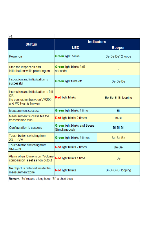
7. Indicators - LED and Beeper
General Operation

15
Power and Bluetooth LED and Beeper for VM200BT

16
8. Default Data Output
The default data output is fixed length described as table,
a space is in between each data column.
‘<2D>’presents the barcode data,
‘<3D>’presents the measurement data;
For example,
<3D> VM200 835DMT900338 CM 27.40 17.70 20.50
27.00 18.00 21.00 66.00 10206.00
<2D>7311271448044
NO.
Data Output
Bytes
of data
Value is
(Example)
Outputted as
(presents a
space)
1
Data Type
identifier
4
<3D> or <2D>
<3D>
2
Model
6
VM200
VM200
3
Serial number
12
835DMT900338
835DMT900338
4
Unit of
measurement
4
CM or INCH
CM
INCH
5
W-Width
(before rounded)
6
20.1
102.4
20.10
102.40
6
H-Height
(before rounded)
6
7
L-Length
(before rounded)
6

17
NO.
Data Output
Bytes of
data
Value is
(Example)
Outputted as
(presents a
space)
8
W-Width (rounded)
6
20.1
102.4
20.00
102.00
9
H-Height (rounded)
6
10
L-Length (rounded)
6
11
Sum of dimension
7
202
202.00
12
Volume
10
10102
10102.00
13
Dimensional weight
7
14
Carriage Return
1
15
Line Feed
1
(Above examples of “Values is”are not relevant to each other, just
for explanation purpose.)
Note:
1. Data values are outputted in fixed length.
2. The output data will be filled a space (presents a
space) ahead in the Integer to comply with the defined
length, filled 0 at the decimal places.
3. If a data-separator is set, the data-separator will be
output in between every two consecutive data.
4. All data are concatenated as an output string and be
transmitted.
5. Customer can configure the data (column no. 5~13) to
be outputted and its sequence in VMSet.

18
9. Configuration Bar Code
Set All Default
USB-VCOM
Interface Selection
<RS232>
Version Information

19
<CR+LF>
Select Terminator
CR
LF
None
Reading Mode
<Good read off>
Trigger On/Off

20
Unit of Measurement
<CM>
INCH
This manual suits for next models
1
Table of contents
Other Champtek Barcode Reader manuals

Champtek
Champtek IG500 User manual

Champtek
Champtek SG700BT Operating instructions

Champtek
Champtek MB200 Series User manual

Champtek
Champtek IG300BT User manual

Champtek
Champtek IG-300 User manual

Champtek
Champtek SLIM S-9080i User manual

Champtek
Champtek IG300BT User manual

Champtek
Champtek SG700BT User manual

Champtek
Champtek SCANTECH ID VM200 User manual


