manuals.online logo
Brands
  1. Home
  2. •
  3. Brands
  4. •
  5. Channel Master
  6. •
  7. Antenna
  8. •
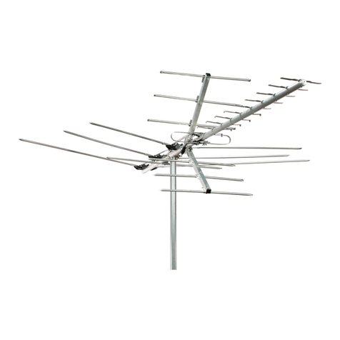
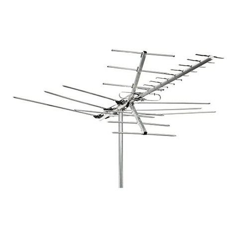
  9. Channel Master 4228HD User manual

Channel Master 4228HD User manual

ClJasse!
Mas/er®
byPCT
Instruction Sheet Model 4228HD
WARNING: Installation of this product near power lines
is
DANGEROUS!
For your safety, read the enclosed "DANGER" booklet before beginning your installation.
Front
Sections
MODEL 4228HD BASIC ASSEMBLY AND MOUNTING
1.
Identify the direction
of
the desired TV stations transmitter by using www.antennaweb.org.
2.
Fold out the 2front sections
of
the antenna making sure to fold out the right and left sections
simultaneously so not to put stress onto the phasing harness. Make sure that the front
sections are straight and parallel with respect to the reflector grid and securely tighten the
8wingnuts (See Fig 1).
3.
Attach the mounting hardware to the antenna as shown in Fig 2.
4. Mount antenna to mast as shown.
5.
Connect coaxial cable to antenna cable connection port. Secure cable to the mast with a
cable tie to prevent strain on the cable connector.
6.
Point the front
of
the antenna toward the TV transmitter location and adjust for best reception.
Note:
The
front
of
the antenna is the side with the Xshaped elements.
7.
Tighten all loose hardware.
Get
the
Clearest
Picture
and SoundlM
",.
~
~
RECEPTION
&CONNECTIVITY
•
~
CONSUMER
&
PROFESSIONAL
DID
PRODUCTS
._oIPCT'"",,""IlonaI
.
..,
www.channelmasterintl.com
Wingnuts
Cable
Connection
Port
Wingnuts
U-bolt
must
be secured
with
bolts
thru
antenna.
Included
Hardware
Channel Master by PCT 2151 East Broadway Road, Ste
211
ITempe, AZ 85282-19331 USA
Tel
+1.480.813.0925 IFax +1.480.545.1080
©2008 Channel Master by PCT adivision
of
PCT International, Inc. RCCPP and Channel Master are trademarks
of
PCT International, Inc. Channel Master trademark is used under license. Specifications subject to change.
All rights reserved. Pub PCTCM.4228HD.INST.20080811
TELEVISION ANTENNA PRODUCTS
LIMITED THREE
(3)
YEARS WARRANTY
This CHANNEL MASTER by
peT
product is warranted to be free from defects in material and
workmanship under normal use and service. CHANNEL MASTER by
PCT
shall repair
or
replace
defective product, at
no
charge. oratits option, refund the purchase price,
if
the product is returned
to
CHANNEL
MASTER
by
PCT
not morethan three (3)
years
after
purchase.
Removal
or
replacement
of
product and its transportation shall
not
be
the
QQst
of
CHANNELMASTER
by
PCT
except CHANNEL
MASTER by
PCT
shall return repaired
or
replaced equipment freight prepaid.
This warranty shall
not
apply
to
product
which has
been
repaired
or
altered in
any
way
so
as
to
affect
is
stability
or
durability,
nor
which
has
been
subject
to
misuse, negligence
or
accident.
This
Warranty
does not cover product which has
been
impaired
by
severe weather conditions such
as
excessive
wind,
~.
storms, lightning,
or
other natural occurrences
over
which CHANNEL MASTER
by
PCT
has
no
control,
nor
shall this Warranty apply to product which has been operated
or
installed other
than in accordance with the instructions fumished by CHANNEL MASTER
by
PCT.
Claimants underthis warranty shall present their claim along with the defectiveproduct to CHANNEL
MASTER
by
PCT
immediately upon failure. Noncompliance with
any
part
of
this claim procedure
may invalidate this Warranty in whole
or
in part.
THIS WARRANTY IS EXPRESSLY
IN
LIEU OF
ALL
OTHER AGREEMENTS
AND
WARRANTIES,
EXPRESSED OR IMPLIED, INCLUDING BUT
NOT
LIMITED TO THE IMPLIED WARRANTIES
OF MERCHANTABILITY AND FITNESS FOR APARTICULAR PURPOSE. CHANNEL MASTER
DOES
NOT
AUTHORIZE
ANY
PERSON TO ASSUME FOR
IT
THE OBLIGATIONS CONTAINED
IN
THIS WARRANTY AND CHANNEL MASTER NEITHER ASSUMES NOR AUTHORIZES ANY
REPRESENTATIVE OR OTHER PERSON TO ASSUME FOR IT
ANY
OTHER LIABILITY
Ito!,
CONNECTION WITH THE PRODUCTDELIVERED
OR
PROVIDED.
IN
NO
EVENT SHALL CHANNEL MASTER BE LIABLE FOR ANY LOSS
OF
PROFITS, LOSS
OF
USE, INTERRUPTION
OF
BUSINESS, ORINDIRECT, SPECIALOR CONSEQUENTIALDAMAGES
OF ANY KIND.
In
no
event shall CHANNEL MASTER be liable for damages in
an
amount greaterthan the purchase
price of the equipment.
Channel
_tor
by
PCT
acivisionofPCTlmIn'IIlionII,lnc..
2151
East8roal:ttwayRoad,S.211IT~.AZIl5282·193JIUSA
TeI.1.llOO.306.8948«·U80.8110925I F
....
,.480.545.10ll0
02(DChannelMa.-byPCT.~rJPCTnIem8lional,n:
CNmel Maler is
nd8rnR
d
PCT
1nIIrnaiIionII,Inc..
The
Channel
Masatrldemlltil
used
LndIr
.....
SpedIcaCionIttqectbdalge.
AI
rights
feSel"\II!lCI.
NI
PCTCM.AnMrnalnItaIINST2Xl807
www.chInMimaterlntt.com
PRODUCTOS PARAANTENA
DE
TELEVISION
GARANTfA L1MITADA POR TRES ANOS (3)
Se garantiza que asta producto
CHANNEL
MASTER por
peT
carece de defectos de materialas y
fabricaci6n en condiciones de uso yservicio normales. CHANNEL MASTER por PCT repararA 0
reemplazara, sin costoalguno, los productosque presenten defectos 0, a su discreci6n, reembolsarA
eJ
precio de compra
si
el producto
es
devuelto aCHANNEL MASTER por PCT amAs tardar tres
arios (3) de la compro.
EI
retiro 0reemplazo del producto y
91
transporte del mismo
no
estarAn a
cargo de CHANNEL MASTER por
PCT
salvo que CHANNEL MASTER par PCT devuelva equipos
reparados 0de reemplazo con transparte prepago.
Esta garantla
no
se aplica alos productos que hayan sido reparados 0alterados de manera que
atecte
su estabilidad 0durabilidad, ni que hayan sido objeto de mal usc, negligencia 0accidentes.
Esta garantia
no
cubre los productos que hayan sido dal'lados
par
condiciones meteorol6gicas
adversas como el viento excesivo, el hielo, las tormentas, los rayos uotros ten6menos dimaticos
naturales tuera del control de CHANNEL MASTER par PCT, ni de aplicara alos productos que
hayan sido utilizados 0instalados de un modo
Que
no coincida con las instrucciones provistas por
CHANNEL MASTER por
PCT.
Aquellas personas que deseen realizar reclamos en virtud
de
esta garantia, deberan presentar su
reclamo junto con al producto defectuoso aCHANNEL MASTER por PCT inmediatamente despues
de la aparici6n de la falla.
EI
incumplimiento de cualquier parte de este procedimiento para la
presentaci6n de
redamos
anulam la garantia en forma total 0parcial.
ESTAGARANTIAREEMPLAZAEXPRESAMENTETODOSLOSDEMAsACUERDOSYGARANTIAS:
EXPRESOS0IMPLIclTOS,lNCLUYENDO,PEROSIN L1MITARSE,ALASGARANTIASIMPLIclTAS
DE
COMERCIALlZACI6N
YADAPTACI6N PARA UN FIN DETERMINADO. CHANNEL MASTER
POR PCT NO
AUTORIZAA
NINGUNA
PERSONAAASUMIR
LAS OBLIGACIONES CONTENIDAS
EN ESTA GARANTIA YCHANNEL MASTER
POR
PCT
NO
ASUME NI AUTORIZA ANINGUN
REPRESENTANTE, U
OTRA
PERSONA A
ASUMIR
NINGUNA
OTRA
RESPONSABILIDAD EN
RELACI6N
CON EL PRODUCTO ENTREGADO 0SUMINISTRADO.
EN NINGUNA CIRCUNSTANCIA CHANNEL
MASTER
POR PCT SERA, RESPONSABLE DE
PERDIDAS DE GANANCIAS, PERDIDA
DE
USC,
INTERRUPCI6N DE LAS ACTIVIDADES
COMERCIALES NI
DANOS
INDIRECTOS, ESPECIALES 0CONSECUENTES
DE
NINGUNA
NATURALEZA.
En
ningun caso CHANNEL MASTER por PCT sera responsable de daftos por un monto superior
al
precio de campra del equipo.
Channel
Meller
por
PCT
I¥Iadivisi6ndePCTI~,tnc
2151
East
Broadlway
Road,
SI8
211
I
Tempe,
AZ85282·1933
I
USA
TeI.\.480.81J.0925I F
....
uao.545.1080
02008Ctlannel
MasllH"porPCT
una
divisi6nde
PCTlmtlm8cionaI,
Inc.
ChllnnelMasieresmarca~dePCTlnI8tn8cion8I,1nc.
LamarcaregistradaCl\annelMesl8fesusadabl;op«rnilo.
E8pecilk:ac:ionoonformeacambio.
Todos
d«echos
son
reseMltbs.
Pub
PCTCMAnt8M8Nt818tion.INST.2OOl107
www.chln.*mutIrintt.com
WATCH FOR WIRES!
You can be KILLED
if this antenna
comes near
electric power lines!
READ
INSTRUCTIONS
ICUIDADO
CON
LOS
CABLES!
.
lSi
esta
antena
entra
en
contacto
.
con
cables
de
alta
tension
puede
ocasionarle
la
MUERTE!
LEA LAS INSTRUCC/ONS
Before you start installation, let
us
worn you of the
danger
of
letting only part of your antenna system
touch electrical power lines - -
you
may
be killed.
Installation
dangerous.
directions.
WARNING!
of
this product near power lines is
For your safety, follow the installation
FOR THE SAFEST INSTALLATION,
FOLLOW THESE PROCEDURES
1.
Perform as much antenna assembly on the ground as possible.
2.
Watch out for overhead power lines. Check the distance
to
the power lines before you start
installing.
WE
RECOMMEND YOU STAYAMINIMUM OF TWICE
THE
MAXIMUM LENGTH
OF
THE
ANTENNA
ASSEMBLYAWAY FROM
ALL
POWER
LINES.
3.
Do
not use ametal ladder.
4. Remember, even the slightest touch
of
an antenna to apower line can cause afatal shock.
5. Do
NOT
try to do the job on awindy day.
6. Have afriend as aspotter when you're on the roof. They can see things you can't.
7.
If
you start to drop an antenna, move away from it and let it fall.
8. If any part
of
the antenna should come into contact with apower line CALL YOUR LOCAL
POWER COMPANY! DO
NOT
TRY TO REMOVE IT YOURSELF! They wil remove it safely.
9. Mast, lead-in, and metal
guy
wires are excellent conductors
of
electrical current - - keep them
away from powerlines too.
10. Be sure your family and friends understand the danger
of
touching an overhead power line.
Tell them never to try to remove
any
object in contact with apower line - -
ca,
TV
antenna,
or
anything else.
11.
Make sure that the antenna mast assembly is properly grounded.
IF AN ACCIDENT SHOULD OCCUR WITH THE POWER LINES:
It happens more often than you realize! Someone
falls off
of
aroof
or
gets the shock oftheir life.
Unfortunately, agood antenna site is often near
electrical power lines. If only metal antenna port
touches apowerline, it completes
on
electrical path
through the installer (that's you).
IADVERTENCIA!
•
La
instalaci6n
de
este producto cerca de cables de
alta tensi6n
es
peligrosa. Para
su
seguridad, siga las
instrucciones de instalaci6n.
Ante decomenzarla instalaci6n, permftanosadvertirle
acerca del peligro de que
el
sistema de la antena
entre
en
contacto con cables de alta tensi6n - -
ya que
pod
ria
ocasionarle
la muerte.
iOcurre mas frecuentemente de
10
que usted cree!
Alguien cae de un techo 0recibe una tremenda
descarga.
Lamentablemente, un buen lugar para la instalaci6n
de una antena amenudo
se
encuentracerca decables
de alta tensi6n.
Si
alguna parte metalica de
la
antena
entra
en
contacto con
un
cable de alta tensi6n, se
com
pi
eta
el
recorrido electrico atraves del instalador
(es decir, usted).
a.
Do
NOT grab hold
of
aperson
in
contact with the antenna and power line. You will be
in
danger and
SUbject to shocking and sever dangerL
b.
Use aDRY board, stick, or rope to push or pull the antenna away from the victim.
c.
Ifthe victim has stopped breathing, and it is safe to approach, administer artificial respiration and stay with
that person.
d.
Have someone call for medical help.
Recommended
by
the National ConsumerProduct Safety Council.
IMPORTANT GUIDELINES
FOR
INSTALLING ANTENNASI
If
you're not sure about careful, safe installation -do
NOT
try to do it yourself. Call for professional
help (look up Television Antenna Systems in your area
or
call your local power company).
Measure the maximum length
of
the antenna and mast assembly and then stay at least twice that
distance away from power lines. (If you don't have at least this much space, hire aprofessional to
do
the installation.)
When using amast for support, use only 11/4 in. diameter
or
largerantenna mast sections.
lengths
over 10 feet should be guyed at least each 10 foot section
PARA
LA
INSTALACION
mas
SEGURA,
SIGA ESTOS PROCEDIMIENTOS
1.
Realice
la
mayor parte de las taraas de montaje de
la
antena en
el
piso.
2.
Cuidese de los cables allreos de alta tensi6n. Verifique
la
distancia que
10
separa de los cables de alta tensi6n
antes de iniciar la instalaci6n •LE RECOMENDAMOS QUE SE MANTENGAA
UNA
DI$TANCIAMINIMA DE
LOS CABLES DE ALTA TENSION
IGUALAL
DOBLE DEL LARGO DEL CONJUNTO DE
LAANTENA.
3. No utilice una escalera metAlica.
4. Recuerde que hasta et contacto rMS Ieve entre Is antena ylos cables de alta tensi6n pueden provocar un
descargo mortal.
5. No intente realizar esta tarea en un dia ventoso.
6. Cuentecon la presencia de otta
pe~
para
que
10
observe mientras 58 encuentra en eltecho. Esta persona
puede ver cosas que usted no ve.
7.
Si
la
antena comienza acaerse, alejese ydejela caer.
8.
$i
cualquier parte de
la
antena antra en contacto con un cable de alta tensi6n - - Comunfquese CON SU
Compania LOCAL DE ELECTRIClDAO,
JNO
INTENTE RETIRARLA USTED MISMOI Ellos
la
retirarfm de
manera segura.
9.
EI
m~sti1,
los cables de acornetida ylos cables metalicos de retenido son excelentes cooductores de la
corriente el6ctrica -mantengalos alejados de los cables
de
alta tensl6n.
10. Asegurese de que sus familiares yamigos compreooan eI peligro que implica tocar un cable aereo de alta
tensi6n. Oigales
que
nunca intenten retirar ningun objeto que 58 encuentre en contaclo cornun cable de alta
tensi6n - • una antena de CB, de
TV
0cualquier otro
e1emento.
11.
Asegurese de que el conjunto del
m~stil
de la antena cuente con una conexi6n atierra adecuada.
YEN
CASO
DE
QUE
OCURRA
UN
ACCIDENTE
CON
LOS
CABLES
DE
ALTA
TENSI6N:
a. No toque a
la
persona que se encuentra en contacto con la antena yel cable de alta tensi6n (Ie ocunira
10
mismo austed).
b.
Utilice una tabla, vara 0cuerda SECA para alejar la antena
de
la victims.
c. Si la victima ha dejado de respirar, administre respiraci6n artifk:ial ypermanezca asu lado.
d. Solicite asistencia medica
Recomendado
per
el
Consejo
Nacional
de
8eguridad
de
Productos para Coosumo.
PAUTAS IMPORTANTES PARA LAINSTALACI6N DE ANTENAS
SI
no esta seguro aceres de c6mo realizar una instalaci6n cuidadosa ysegura -no intente hacerlo usted mismo.
Solicite ayuda profesional (en las
p~ginas
Amarillas,
en
la
secci6n
de
Sistemas deAntenas
de
Televisi6n 0en su
compa/Ua de electricidad local).
Mida la Iongitud
m~xima
del conjunto
de
antena y
m~stil
yluego ahijese al menos el doble de esa distancia de k)S
cables de alta tensKm. (Si no cuenta con ese
espado,
contrate aun profesional para realizar Is tarea).
Para sostener el
m~stil,
utilice unicamente soportes para
rMstiles
de
antenas
de
un
diamelro
de
1
1/4
poIgadas
0
superior.
las
IongiIudes
superiores
a
10
pies
deben
aIrioslrarse
lXlfI
cables
aI
menos
<:ada
10
pies.
TYPES OF SUPPORT STRUCTURES AND MOUNTING
SITE SELECTION
WHERE TO INSTALLYOUR ANTENNA
Before attempting
to
install
your
antenna. think where you can
best
place
your
antenna for safety
and performance. DESCRIPTION USAGE HEIGHT LIMITATION
To
determine asafe distancefrom wires.
power
lines. and trees:
1.
Measure the height
of
your
antenna.
2.
Add
the
antenna
length
to
the
length
of
your
tower
or
masl,
and
then
3.
Double this total for the minimum recommended safe distance.
If
you
are
unable
to
maintain
this
safe
distance,
STOPI
GET
PROFESSIONAl
HELP.
Most antennas are supported
by
pipe
masts
attached to the chimney, roof,
or
side
of
the house.
Normally, the higher the antenna is
above
ground, the better it performs. Agood general rule is to
install
your
vertical antenna about 5to 10 feet above the roof line and as
far
away
as possible from
power line and obstructions.
Tripod mount
Roof
mount
Wall mount
Chimney mount
Tower
Telescoping mast
Peaked and flat type roofs
Peaked
and
ftat
type
roofs
Side
of
structure
Chimney
only
Not recommended.
Not
recommended.
10
feet above rooftop
10
feet
above rooftop
10
feet
above rooftop
10 feet above chimney top
For professional
use
only
For
professional use only
NOTE:
IF
ANTENNA
IS
MOUNTED
HERE
OR
HERE
.""JI"";
THE
SAFE
DISTANCE
FROM
POWER
LINES
SHOULD
BE
TWICE
THE
HEIGHT
OF
THE
MAST
PLUS
THE
HEIGHT
OF
THE
ANTENNA
SAFEST
LOCATION
TIPOS DE ESTRUCTURAS
DE
SOPORTE YMONTAJE
SELECCI6N
DE
LA
UBICACI6N
D6NDE
INSTALAR
LA
ANTENA
Antes de intentar lostalar
Is
solana,
piense
d6nde
puede coIocar1a para
obtener
Ia
mayor
seguridad
y
el
mejordesempetlo.
DESCRIPCI6N USO ALTURA
Afin de determinar una distancia segura
de
los cables, cables
de
atta tensi6n yilrbo&es:
1. Mida la altura
de
la solana.
2. Sume dicha longitud ala longitud
de
la
torre 0mcistil, yluego.
3. Duplique esta longitud para
obtener
la distancia de seguridad
minima
recomendada.
Si
no
Ie
es
posible mantener
esta
distanda
de seguridad.
iDETENGASEl
SOLICITE AYUDA
PROFESIONAL.
La
mayoria
de
las
antenasestan sostenidas
par
rnastiles
de
caI\o
que
se
ajustan a
las
chimeneas,
al
techo
0a
las
paredes
laterales
de
Ia
vivienda.
En
general,
cuanto
mas
aIejado del
suelo sa encuentra la antena. majores resultados obtendrct
Una
practica recomendable
es
instaJar
su
antena
vertical
entre
5 y
10
pies
par endma
de
Ia
linea
del
lecho y
10
mas
Iejos posible
de
los
cables
de
atta tensi6n ylos obstaculos.
Montaje en trfpode
Montaje en
lecho
Montoje en parades
Montaje en c."limenea
To""
Mastil tetesc6pico
Techos.
doIeguas
0
planas
Techoe.
dol
eguas
0ptanos
Lateral
de
Ie
estructura
Unlcllrnente en
chimeneas
No
..
recomIendo.
No
58
recomlendo.
10
pies
parendm8
de
Is azotea
10 pies
pol'
endme
de
Is azotea
10 pies
pol'
endme
de
Ia
azotea
10 pies
par
endme del final
de
la
boca
de
la chimenea
Unlcwnente pera
usa
profesional.
UnlcamenIe pera
usa
profeslonal.
NOTA:
51
LAANTENASE
COLOCA
AQUI
0
AQUI.,.
LA
DISTANCIA
DE
SEQURIDAD
DE
LOS
CABLES
DE
ALTA
TENSION
DEBE
SER
IGUAL
AL
DOBLE
DE
LA
ALTURA
DEL
MAsTIL MAs LAALTURA
DELAANTENA
UBICACI6N
MAs
SEQURA
3000hrn
transmission
line
'r-r.1=,...,.,I.)
Ground
wire
from
mast
ANTENNA DISCHARGE UNIT
HOW TO INSTALLYOUR ANTENNA
1.
Assemble your new antenna on the ground in accordance with separate assembly instructions
supplied with it.
2. On the ground, clamp antenna to mast. pull enough transmission line to connect to antenna.
3.
Install selected mounting bracket.
4. If you are going to use
guy
wire installation instead
of
amounting bracket:
Install-guy anchor bolts
•Estimate length
of
guy
wire and cut
•Attach to mast using
guy
ring
5.
Mount the extra included
~Warning
Laber
supplied in the hardware bag on the antenna mast at
eye level after installation as been completed.
LIGHTNING PROTECTION
To
protect your house and your
TV
(FM, CB, etc.) installation, the mast
of
your antenna system
must
be properly grounded. Drive a4to 8foot ground rod as close as possible
to
the antenna supporting
structure or antenna base. Then connect a
#8
(or larger) copper or aluminum wire between the base
of the antenna and the ground rod. Also, an antenna discharge unit (sometimes- referred to as a
lightning arrester) should
be
connected to the antenna lead-in atthe place where it enters the
home.
(Follow the instructions provided with the static discharge unit.)
ANTENNA REMOVAL
Removal
of
the antenna should be exactly the reverse
of
the installation instructions. Please, for
your own safety, follow the instructions for installing the antenna starting with the last step first.
This is the safest method.
CHIMNEY MOUNT
SIDE OF HOUSE MOUNTING
Where
roof
overhang is not excessive.
the
side
of
the
house provides aconvenient mounting. Positton the brackets
over astud
if
possible. one above the other, and space two
or
threefeet apart. For metal siding, first
mark
mounting holes, then
drill pilot holes through the siding to accept mounting screws.
Apply roofing compound
around the base of the
bracket, screws and eyebolts
for moisture sealing.
Installations involving atripod mount and a
mast should be guyed
if
the mast is 10 feet
or
more. Tripod
mount
must be securely
anchored to the roof
as
should
the
guy
wires.
NOTE: Mountthe extra "Warning Label" supplied with the
antenna hardware to
the
mast at
eye
level after installation
has been completed.
CHIMNEY MOUNTING
The chimney is often an easy and convenient mounting
location. Note that the chimney
must
be
strong enough
to
support the antenna in htgh winds.
Do
not use achimney
that has kx>se bricks
or
mortar. A
good
chimney
mount
makes use
of
a5
or
10 foot 11/4 in. diameter steel mast.
and aheavy-<luty
two
strap
damp-type
bracket. Install
the upper bracket below the
top
course of bricks, and the
lower bracket two
or
three feet below the upper bracket.
For maximum strength, space the brackets as much as
possible.
"UNIVERSAL"
ROOF MOUNT
ROOF MOUNTING
The
swivelfeature
of
·universal-type mounting brackets
makes aconvenient antenna mount for flat
or
peaked
roofs.
One
clamp type bracket is used
with
3
or
4guy
wires equally spaced around the mast and anchored
to
the
roof
or
eaves
by
eyebolts.
WALL
MOUNT
Cable
de
conexi6n
Linea
de
a
tierra
del
mastil
transmisi6n
de
r------,
3000hmlo.
,,",",==::I'""'T1I..J
REMOCI6N DE
LA
ANTENA
La remoci6n de la antena debe realizarse siguiendo las instrucciones de instaraci6n en sentido
inverse. Por su seguridad, siga las instrucciones para la instalaci6n de la antena comenzando par
el ultimo paso.
Es
la (mica manera segura de retirar la antena.
C6MO
INSTALAR
LAANTENA
1. Monte su nueva antena en el piso de acuerdo con las instrucciones de montaje provistas.
2. En el piso, ajuste la antena al mllstil, prepare una longitud suficiente de linea
de
transmisi6n para
conectarla ala antena.
3.
Instale el soporte de montaje seleccionado.
4.
8i
desea utilizar cables de retenido en lugarde un soporte de montaje:
Instale parnos de anclaje de retenida
•Calcule la longitud del cable de retenida yc6rtelo
•Ajustelo al mllstil con un anillo de retenido
5.
Una vez finalizada la instalaci6n, coloque en el
mllstilla
etiQueta de advertencia provista junto con
la antena, ala altura de la vista.
PROTECCI6N CONTRA RAYOS
Para proteger su vivienda y su instalaci6n de
TV
(FM, CM, etc
...
),
el mllstil del sistema de antena
debe contar con una conexi6n atierra adecuada. Coloque una varilla
de
conexi6n atierra de
4'
a
8'
10
mas cerca posible de la estructura de soporte de la antena 0de la base. Luego, coloque
un
alambre#8
(0
mas grueso) de aluminio 0cobre entre la base de la antena yla varilla de conexi6n
atierra. Tambien debe conectar una unidad de descarga de la antena (a menudo denominado
supresor de rayos) al cable de acometida de la antena, en
e/lugar
en el
que
ingresa ala vivienda.
(8iga
las instrucciones provistas junto con la unidad de
d~rga
de
eslatica).
UNlOAD DE DESCARGA DE ANTENA
MONTAJE EN CHIMENEA
Aplique
mazda
para tachos
alrededor de la base del
soporte, los tomillos ypernos
de anilla para I09rar
un
sellado contra
humedad.
Las instalaciones
con
un
soporte
trfpode y
un
mllstil deben
arriostrarse
si
el mllstil liene
diez 0
mlIs
pies de altura.
EI
soporte
de
trfpode
debe
sujetarse firmemente
al
tacho
al igual
que
~
cables de
retenida.
MONTAJE EN
LA
PARED
LATERAL
DE
LA
VIVIENDA
Cuando la saliente del techo
no
asexcesiva,
ta
pared lateral
de
Ia
vMenda
as
un
lugar
de
montaje adecuado..De ser posibfe, coIoque los soportes
sobre un espllrrago,
uno
sobre
eI
otro,
con
una separaci6n de dos 0
tres pies.
En
el caso de los recubrimientos metlllicos, primero marque
los orificios de montaje, luego perfore los orificios gufa atraves del
recubrimiento para colocar los tornillos de montaje.
MONTAJE
EN
TECHO
La caracterfstica giratoria
de
los soportes de montaje
·universales- hace
que
sean
un
tipo de montaje
adecuado para techos a
dos
aguas 0p(anos.
sa
utiliza
un
soporte
de
tipo abrazadera
con
304cables de
retenida colocados 'a distancias equivalentes
alrededor del mllstil ysUjetados al tacho 0alero
pormedio de
pernos
de
anUla.
Para realizarun buen montajeenchimenea debeutilizarse
un
mbtil
deaoore 5 0
10
pies y 1 1/4"
de
diamelro,
asi
como
un
soporte detipo abrazadera con
dos
f1ejes
dealta resistencia.
Instale el soporte inferior al menos 2 0 3 pies por debajo det
soporte superior. Para obtenerla mlIxlma resistencia, separe
los soportes tanto
como
sea posible.
MONTAJE EN
LA
PARED
MONTAJE
EN
CHIMENEA
Amenudo, la chimenea
es
un
lugar conveniente ysancillo
para realizar el montaje. Pero la chimenea debe
ser
10
suficientemente resistente
como
para sostener
Ia
antena en
caso de vientos fuertes.
No
utilice una chimenea
que
tenga
ladrillos 0oomento fIojo.
MONTAJE "UNIVERSAL"
ENTECHO
NOTA: Una vez finalizada
Ia
in.tataci6n, coloque
en
el
mastilla
etiqueta
de
advertencia provistajunto con
Ia
antena,
ala altura de Ia vista.
IF
ANTENNA
SUPPORTING
STRUCTURE
DOES
NOT
HAVE
A
··DANGER"
LABEL.
ATTACH
THE
LABEL
TO
A
PLAINLY
VISIBLE
PART
OF
THE
BASE
OF
THE
SUPPORTING
STRUCTURE
(MAST.
TOWER.
POLE.
ETC.).
81
LA
STRUCTURE
QUI
SOU
TIENT
L'ANTENNE
N'A
PAS
D'ETIQUETTE
DE
-DANGER-,
VEUILLEZ
ATTACHER
L'ETIQUETTE
A
UNE
PARTIE
BIEN
VISIBLE
DE
LA
STRUCTURE
DE
SOUTENEMENT
(MAT,
PYLONE,
POTEAU,
ETC.)

Other Channel Master Antenna manuals

Channel Master Digital ready User manual

Channel Master

Channel Master Digital ready User manual

Channel Master DIGITAL ADVANTAGE CM-2016 User manual

Channel Master

Channel Master DIGITAL ADVANTAGE CM-2016 User manual

Channel Master CM-4040 User manual

Channel Master

Channel Master CM-4040 User manual

Channel Master 2016 User manual

Channel Master

Channel Master 2016 User manual

Channel Master CM-3016 User manual

Channel Master

Channel Master CM-3016 User manual

Channel Master CM-0500V2 User manual

Channel Master

Channel Master CM-0500V2 User manual

Channel Master 3010 User manual

Channel Master

Channel Master 3010 User manual

Channel Master 6392 User manual

Channel Master

Channel Master 6392 User manual

Channel Master 6920 User manual

Channel Master

Channel Master 6920 User manual

Channel Master Advantage 3014 User manual

Channel Master

Channel Master Advantage 3014 User manual

Channel Master CM-9521A User manual

Channel Master

Channel Master CM-9521A User manual

Channel Master CM-3000HD User manual

Channel Master

Channel Master CM-3000HD User manual

Channel Master SMARTenna 3000A User manual

Channel Master

Channel Master SMARTenna 3000A User manual

Channel Master 3018 User manual

Channel Master

Channel Master 3018 User manual

Channel Master CM-0747 User manual

Channel Master

Channel Master CM-0747 User manual

Channel Master 960 I User manual

Channel Master

Channel Master 960 I User manual

Channel Master Metro CM-4030HD User manual

Channel Master

Channel Master Metro CM-4030HD User manual

Channel Master CM-3016 User manual

Channel Master

Channel Master CM-3016 User manual

Channel Master CM-4220HD User manual

Channel Master

Channel Master CM-4220HD User manual

Channel Master 243 User manual

Channel Master

Channel Master 243 User manual

Channel Master FLATenna User manual

Channel Master

Channel Master FLATenna User manual

Channel Master 4221 User manual

Channel Master

Channel Master 4221 User manual

Channel Master 4220HD User manual

Channel Master

Channel Master 4220HD User manual

Channel Master 75cm Elliptical Triple-Beam User manual

Channel Master

Channel Master 75cm Elliptical Triple-Beam User manual

Popular Antenna manuals by other brands

M2 2M HO LOOP manual

M2

M2 2M HO LOOP manual

Microwave Radio Communications Ellipse 2000 installation guide

Microwave Radio Communications

Microwave Radio Communications Ellipse 2000 installation guide

Wilson Electronics 304452-50 installation guide

Wilson Electronics

Wilson Electronics 304452-50 installation guide

Hy-Gain AV-640 Instruction & assembly manual

Hy-Gain

Hy-Gain AV-640 Instruction & assembly manual

Siklu EtherHaul 8000 Series Installation, operation and maintenance manual

Siklu

Siklu EtherHaul 8000 Series Installation, operation and maintenance manual

Antenna Experts AY-390 installation manual

Antenna Experts

Antenna Experts AY-390 installation manual

Keysight N6850A user guide

Keysight

Keysight N6850A user guide

Sirio Antenne SY-910 installation manual

Sirio Antenne

Sirio Antenne SY-910 installation manual

AC Antennas KUM400 Series installation guide

AC Antennas

AC Antennas KUM400 Series installation guide

Feig Electronic ID ANT.U290/290-EU installation manual

Feig Electronic

Feig Electronic ID ANT.U290/290-EU installation manual

Panorama Antennas SW3-875 LGMQM4 Series Installation instruction

Panorama Antennas

Panorama Antennas SW3-875 LGMQM4 Series Installation instruction

UI PBE-2AC-400 quick start guide

UI

UI PBE-2AC-400 quick start guide

Directive Systems & Engineering DSE2045LY quick start guide

Directive Systems & Engineering

Directive Systems & Engineering DSE2045LY quick start guide

MAPLE WIRELESS 11dBi user manual

MAPLE WIRELESS

MAPLE WIRELESS 11dBi user manual

Directive Systems & Engineering DSE3318LYRMK quick start guide

Directive Systems & Engineering

Directive Systems & Engineering DSE3318LYRMK quick start guide

Ubiquiti PBE-2AC-400 quick start guide

Ubiquiti

Ubiquiti PBE-2AC-400 quick start guide

SMA EXTANT-US-40 installation manual

SMA

SMA EXTANT-US-40 installation manual

Intellian v130 Installation and operation manual

Intellian

Intellian v130 Installation and operation manual

manuals.online logo
manuals.online logoBrands
  • About & Mission
  • Contact us
  • Privacy Policy
  • Terms and Conditions

Copyright 2025 Manuals.Online. All Rights Reserved.