Antenna Assembly
Additional product information including videos and frequently asked questions is
available at www.channelmaster.com/support
Warranty Information is available online at www.channelmaster.com/warranty
Rooftop Installation Warning!
Use caution when installing antennas and accessories on a rooftop, near power lines and electrical equipment. Stay away from power lines. If you or the antenna comes in contact with power wires or other
electrical equipment you could be at risk of serious injury or even death. If any part of the antenna should come in contact with a power line, call your local power company for assistance, DO NOT TRY TO REMOVE
IT YOURSELF. If you are concerned about nearby power lines coming in contact with you or your antenna during installation, please contact a professional installer and/or your power company for assistance.
CM-1776 REV-A 6/14/2022
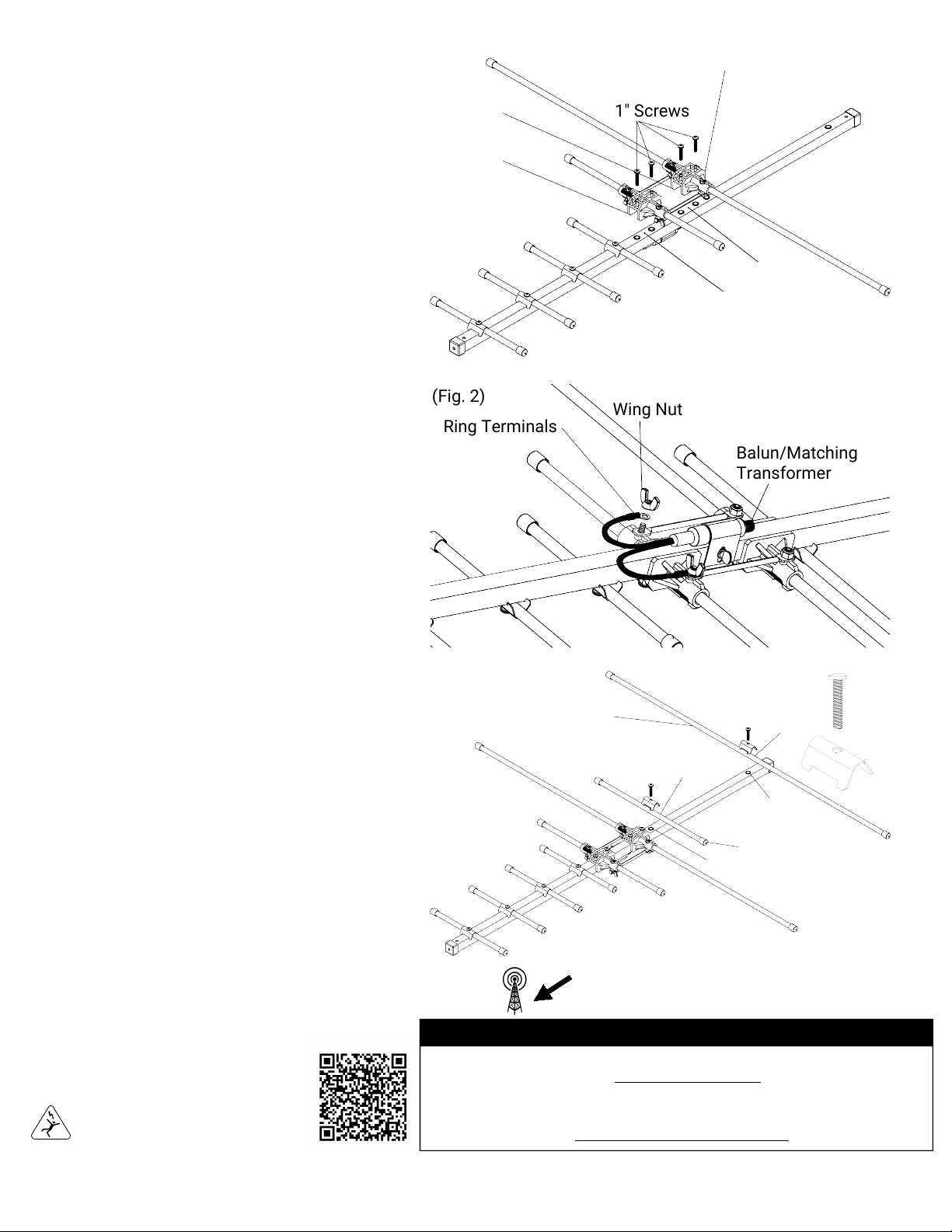
(Fig. 2)
Center Element Assembly
1" Screws
(Fig.1)
Step 1. (Figure 1)
Attaching the Center Element Assembly to the
Antenna: Place the plastic Center Element Assembly
labeled A and B onto the square tube of the antenna
as shown. Line up the four holes in the plastic
brackets with the 4 threaded holes in the square
tube. (Plastic bracket A attaches to location A on the
square tube using 2 of the included 1” Screws.
Plastic bracket B attaches to location B on the
square tube using 2 of the included 1” Screws.) Insert
screws through the holes in the plastic bracket and
screw into the threaded holes on the square tube,
tighten with a phillips screwdriver.
(It is important that the Center Element Assembly is
installed in the correct direction, performance will be
affected if installed in the incorrect direction. Refer to
image for the correct direction/orientation of the
Center Element Assembly.)
Step 2. (Figure 2)
Connecting the Balun/Matching Transformer to the
Antenna: Remove the two Wing Nuts from the center
element assembly as shown. Connect the two Balun/
Matching Transformer Ring Terminals to the screws,
then reinstall and tighten the two Wing Nuts using
just your hand and a phillips screwdriver to prevent
the screw from spinning.
Step 3. (Figure 3)
Attaching the Reflector Elements to the Antenna:
Using one of the included Element Brackets and one
of the included 1” Screws attach the 12” Reflector
Element labeled C (shortest length round tube) to the
square tube as shown. Next, use the other Element
Bracket and1” Screw to attach the 31” Reflector
Element labeled D
(longest length round tube) to the square tube as
shown. Tighten all screws using a phillips
screwdriver. (It is important that the two reflector
elements are installed in the correct location on the
square tube. Performance will be affected if installed
in the incorrect location. Refer to image for the
correct placement locations for the two reflector
elements.)
D
D
12" Reflector Element
(Short)
C
C
31" Reflector Element
(Long)
B
A
A
B
1"
Screw
Element
Bracket
Wing Nut
Ring Terminals
Balun/Matching
Transformer
- - - - - - - - - - - - - - - - - - - - - - - - - - - - - - - - - -
MORE INFORMATION
www.channelmaster.com
(Fig.3)
- - - - - - - - - - - - - - - - - - - - - - - - - - - - - - - - - -
Scan For
Video
Tutorial
* Bottom View
Point Front of antenna to the TV transmitters.
* Top View
*Front


