SITE
SELECTION
WHERE
TO
INSTALL
YOUR
ANTENNA
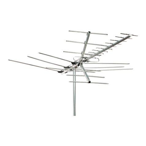
Before attempting to install your antenna, think where
yo~o
can best place
your antenna for safety and performance.
To
determine a safe distance from wires, power lines, a.,d trees:
1. Measure the height
of
your antenna.
2. Add the antenna length to
t~e
length
of
your tower or mast, and then
3. Double this total for the rninimum recommended safe distance.
~~~~:r~~~~a~~~~~n~~i~~=~~~~ig;~!d
~~~~~~em~~gp~tt~~~~~~~~sc~~~~:;
roof, or side
of
the house. Normally, the higher the antenna is above ground,
the better it performs. A good general rule is to install your vertical antenna
about 5 to 10feet
atuve
the roof line and
as
far away
as
possible from power
line and obstructio,s.
SELECCION
DE
LA
UBICACION
DON
DE
INSTALAR
LA
ANTENA
Antes de intentar instalar
Ia
antena, piense d6nde puede colocarla para
obtener Ia mayor seguridad y el mejor desempefio.
A fin
de
determinar una distancia segura
de
los cables, cables de alta
tensi6n y arboles:
1.
Mida
Ia
altura de
Ia
antena.
2.
Sume
dicha longitud a
Ia
longitud
de
Ia terre o
mastil,
y luego.
3.
Duplique esta longitud para obtener Ia distancia
de
seguridad minima
recomendada
.
Si
no
le es posible mantener esta distancia de seguridad, jOETENGASE!
SOLICITE
AYUDA
PROFESIONAL.
La
mayorla
de
las
anlenas
estan
sostenidas par mastiles de cane que se ajustan a las chimeneas, al
techo o a las paredes laterales
de
Ia vivienda. En general, cuanto
mas alejado del suelo se encuentra Ia antena, mejores
resultados
obtendr.i
Una pr8ctica recomendable
es
instalar su antena vertical entre 5 y 10 pies
par encima de
Ia
linea del techo y lo
mas lejos posible
de
los cables
de alta tensi6n y los
....
~
obstaculos.
~
TYPES
OF
SUPPORT
STRUCTURES
AND
MOUNTING
DESCRIPTION
USAGE
_HEiGHlliMIIAIIllli
Tripod
mount
Peaked
and
flat
type
roofs
10
feet
abo
ve
rooftop
Roof
mount
Peaked
and
flat
type
roofs
10
feel
abo
ve
rooftop
Wall
mount
Si
de
of
structure
10
feel
above
rooftop
Chimney
mount
Chimney
only
10
feet
above
chimney
top
Tower
Not
recommended.
For
professional
use
only
Telescoping
mast
Not
recommended
.
For
professional
use
only
NOTE
:
IF
ANTENNA
IS
MOUNTED
HERE
OR
HERE
~
TH,;
eA,.e
DISTANCE
FROM
POWER
LINES
SHOULD
BE
TWICE
THE
HEIGHT
OF
THE
MAST
PLUS
THE
HEIGHT
OF
THE
ANTENNA
TIPOS
DE
ESTRUCTURAS
DE
SOPORTE
Y
MONTAJE
DESCRIPCION
USO
ALTURA
Montaje
en
tripode
Techos
a
dos
aguas
o
pianos
10
pies
por
encima
de
Ia
azotea
Montaje
en
techo
Techos
a
dos
aguas
o
pianos
10
p
ies
por
encima
de
Ia
azotea
Monto
je
en
paredes
Lateral
de
Ia
es
t
ructura
10
pies
por
encima
de
Ia
azote
a
Montaje
en
chimenea
Un
i
camente
en
chimeneas
10
pies
por
encima
de
l
final
de
Ia
boca
de
Ia
chimenea
Torre
No
se
recomiendo
Unicamente
para
uso
profesional
Unicamen
te
para
uso
profesional
Mastiltetesc6p
ico
No
se
recomiendo
NOTA:
SllAANTENASE
COLOCA AQUI 0
AQUL
A LA DISTANCIA
DE
SEQURIOAD
DE
LOS
CABLES
DE
ALTA TeNSI6N DEBE
SER
IGUAL AL DOBLE
DE
LAALTURA
DEL MASTIL MAS LA ALTURA
DE
LAANTENA
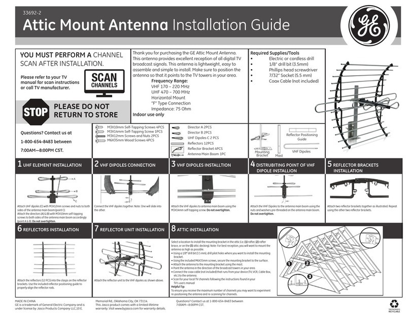
ROOF
MOUNTING
The swivel feature
of
Muniversal" type mounting
brackets makes a convenient antenna mount for
flat or peaked roofs.
One
clamp type bracket
is used with 3 or 4 guy wires equally spaced
around the mast and anchored to the roof
or
eaves by eyebolts.
Installations involving a tripod mount and a
mast should be guyed
if
the mast is 10 feet
or
more. Tripod mount must be securely
anchored to the roof as should the
guy wires.
~
Apply
roofing
compound
around the base
of
the bracket,
screwsandeyeboltsformoisture
sealing.
"UNIVERSAL
"
ROOF
MOUNT
SIDE
OF
HOUSE
MOUNTING
Where roof overhang is not excessive, the side
of
the house
provides a con
ve
nient mounting. Position the brackets over
•
a stud if possible, one above the other, and space two or
~
. three feet apart.
For
metal siding, first mark mounting holes,
:;/""-:::::::=::
then drill pilot holes through the siding to accept mounting
screws.
CHIMNEY
MOUNTING
::.--::::
...
The chimney is often an easy and convenient
WALL
MOUNT
mounting location. Note that the chimney
must be strong enough to support
the antenna
in
high winds. Do not
use a chimney that
has
loose bricks or mortar.
A good chimney mount makes use
of
a
5
or
10 foot 1 1/4 in. diameter steel mast, and a
heavy-duty two strap clamp-type bracket. Install ""-
the upper bracket below the top course
of
bricks,
and the l
ower
bracket two or three feet below the
upper bracket. For maximum strength, space the
brackets as much
as
possible.
NOTE:
Mount
the
extra
"Warning
Lobel"
supplied
with
the
antenna hardware
to
the
most
ot
eye
level
after
installation
hos
be.e.n
eomplete.d.
MONTAJE
EN
TECHO
La caracteristica
~iratoria
de los soportes
de
~~n~~J~
u~~~z~~~~s~a~:~~uoes
s;~~~na~e~sd~
pianos.
Se
utiliza un soporte de tipo abrazadera
con 3 o 4 cables
de
retenida colocados a
distancias equivalentes alrededor del mastil
y sujetados
at
techo o alero per
medic
de
pemos
de
anilia.
Las instalaciones con un soporte de triP.ode
y un mastil deben arriostrarse si el mastil
tiene diez o mas pies
de
altura. El
s~f~~~e~~
~~
1
fe
0
cdh~
~~8~ats~~~T~e
~
'
cables
de
retenida.
Aplique mezcla para techos
alrededor de Ia base del
""
soporte, los tomillos y pernos
"-.
~
de anilla para lograr un sellado
contra humedad.
MONTAJE
"UNIVERSAl~
EN
TECHO
MONTAJE
EN
LA
PARED
LATERAL
DE
LA
VIVIENDA
:....---
• Cuando
Ia
saliente del techo no es excesiva,
Ia
pared
lateral de
Ia
vivienda es un Iugar de montaje adecuado.
De
ser posible, coloque los soportes sobre un esparrago,
uno
sabre el otro, con una separaci6n
de
dos o Ires pies.
En el case
de
los recubrimientos metalicos, primero
marque los orificios de montaje, luego
peliore
los orificios
guia
a !raves del recubrimiento para colocar los tornillos
de
montaje.
MONTAJE
EN
LA
PARED
MONTAJE
EN
CHIMENEA
A menudo, Ia chimenea es un Iugar
conveniente y sencillo para realizar el montaje. Pero
Ia
chimenea debe ser lo suficientemente resistente
como para sostener Ia antena en
caso
de
vientos
fuertes
•.
No
utilice una chimenea
que
tenga ladrilles
o cementa ftojo.
Para realizar un buen montaje en chimenea debe
utilizarse un mastil
de
acero
5o
10 pies y 1 1/4" de ,
di8metro, asi como un soporte de
t1po
abrazadera '
con des ftejes de alta resistencia. Instate el soporte
inferior
at
menos 2 o 3 pies per debajo del soporte
superior. Para obtener
Ia
maxima resistencia,
separe los soportes tanto como sea posible.
NOT
A:
Una
vez finalizado
Ia
instolaciOn,
coloqu£
en
el
mOstil
Ia
e.tique.ta de adve:rtencia provista junto
con
Ia
antena. a
to
altura
de:
Ia
vista.
HOW
TO
INSTALL
YOUR
ANTENNA
1.
:;;::;::g
1
t;
i~~~r~~~~n~~t~~~tfe~nwti~~
i?.round in accordance with separate
2. On the ground, clamp antenna to mast, pull enough transmission line to
connect to antenna.
3.
Install selected mounting bracket.
4. If you are going to
use
guy wire installation instead
of
a mounting
bracket:
Install-guy anchor bolts
• Estimate length
of
guy wire and cut
• Attach to mast using guy ring
5.
Mount the extra included
"W
arning Label" supplied in the hardware bag
on the antenna mast
at
eye level after installation as been completed.
ANTENNA
REMOVAL
Removal
of
the antenna should be exactly the reverse
of
the
installation instructions. Please, for your own safety, follow the
~~i~~~t:~~ssa~~st
i~~f~~
the antenna starting with the last step first.
LIGHTNING
PROTECTION
To
protect your house and your
TV
(FM, CB, etc.) installation, the mast
of
your
antenna system must be properly grounded.
Drive a 4 to 8 foot ground rod
as
close
as
possible to the antenna supporting
~i%c~~~~~~~~~~~sbea~it~~:~~;~~~e~~g
~~
(o~~~~~e~bd~~~~~~~~~g;~~un~
discharge unit (sometimes- referred to as a
~ghtning
arrester) should be
connected to the antenna lead-in at the place where it enters the home.
(Follow the instructions provided with the static discharge unit.)
ANTENNA
DISCHARGE
UNIT
COMO
INSTALAR
LA
ANTENA
1.
Monte su nueva antena en el piso de acuerdo con las instrucciones
de
montaje provistas.
2. En el piso, ajuste
Ia
antena al m8stil, prepare una longitud suficiente
de
linea de transmisi6n para conectarla a
Ia
antena.
3.
Instate el soporte
de
montaje seleccionado.
4. Si desea utilizar cables
de
retenido en Iugar
de
un soporte de montaje:
• Instate pernos
de
anclaje de retenida
• Calcule
Ia
longitud del cable de retenida y c6rtelo
• AjUstelo al mastil con un anillo de retenido
5. Una vez finalizada
Ia
instalaci6n, coloque en el mastil
Ia
etiqueta de
advertencia provista junto con
Ia
antena, a Ia altura
de
Ia
vista.
REMOCION
DE
LA
ANTENA
La remoci6n
de
Ia
antena debe realizarse siguiendo las instrucciones
de
instalaci6n en sentido inverse. Per su seguridad, siga las instrucciones para
Ia
instalaci6n de
Ia
antena comenzando par el Ultimo paso. Es
Ia
Unica
manera segura de retirar Ia antena.
PROTECCION
CONTRA
RAYOS
Para protegersu vivienda ysu instalaci6n
de
TV (FM,CM, etc...),el mastil del
sistema
de
antena debe
contarcon
una conexi6na tierra adecuada. Coloque
una varilla
de
conexi6n a tierra de 4' a 8'
to
mas
cerca posible de
Ia
estructura
de
soporte de Ia antena
ode
Ia base. Luego, coloque un alambre#8 (o
mas
grueso)
de
aluminioo cobreentre
Ia
base
de
Ia
antenayIavarilla
de
conexi6na
tierra. Tambien
debe
conectarunaunidad dedescarga
de
Ia
antena(amenu
do
denominado
S U p r e S 0 r UNlOAD DE OESCARGA
DE
ANTENA
de
rayos)
al
cable
de
acometida de
Ia antena, en
el Iugar
en
el
que ingresa
a
Ia
vivienda.
(Siga
las
instrucciones
pro
v
istas
junto con
Ia
unidad
de
descarga
de
est3tica).


